Robin-SLAC-invited-talk
Robin-SLAC-invited-talk
Robin-SLAC-invited-talk
- No tags were found...

You also want an ePaper? Increase the reach of your titles
YUMPU automatically turns print PDFs into web optimized ePapers that Google loves.
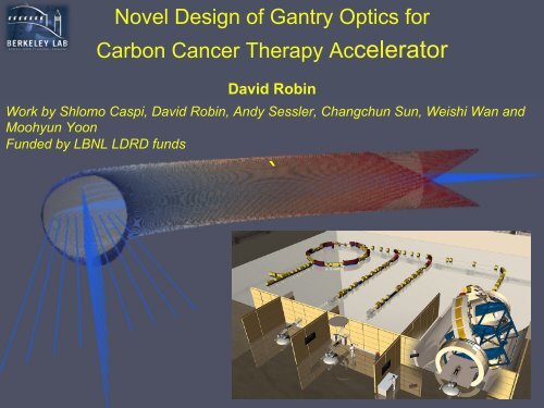
Novel Design of Gantry Optics forCarbon Cancer Therapy AcceleratorDavid <strong>Robin</strong>Work by Shlomo Caspi, David <strong>Robin</strong>, Andy Sessler, Changchun Sun, Weishi Wan andMoohyun YoonFunded by LBNL LDRD funds`
Outline• Introduc+on to Ion Beam Therapy • What is a Gantry? • Novel Superconduc+ng Gantry Magnet Coil Design Op+mized with Gene+c Algorithms • Tracking Results • Future Plans
A Proton Therapy Center(University of Florida)• Mix of a largeaccelerator facility anda complex medicaltreatment facilityProtons.Three Gantries,One Horiz. BeamFootprint: 98000 sq ft$125M
Combined Carbon and Proton Facility Heidelberg IonTherapy (HIT) Center at Heidelberg University Hospital• Developed and designed as a collaboration of University ofHeidelberg & GSI Accelerator Laboratory in Darmstadt.
Growth Ion Beam Therapy> 60,000 pa(ents treated with Protons > 6,000 pa(ents treated with Carbon
Present and Proposed FacilitiesCarbon facilities consist of 7 in Europe and 6 in Asiaand still more are planned; none in the US
Cell Killing Mechanism Goal of radiation therapy is to use radiation to kill cancer tumortissues while minimizing damage to healthy tissueInduce significant DNA damage to prevent cell replication
Ion Beam Cancer Therapy• Ion Beam Therapy (IBT) is the use of ion beams (protons and other ions) totreat tumors.• IBT was proposed by Robert Wilson to take advantage of the Bragg Peak.Radiology 47, pp. 487–491, 1946
Energy deposited by differentionizing radiationDose versus depth• X-rays deposit most of their energy near the body entrance• Ions (such as protons and carbon) concentrate more dose at thetumor‒ Less in front‒ Little or none beyond
Tuning the penetration depth with ionsBragg Peak• The depth of the energy depositionpeak (Bragg peak) can be efficientlytuned by changing the ion energyNote – For the same penetra=on depth as protons carbon requires beams with higher magne=c rigidity è larger accelerators
Ion Beam “Scanned” over tumorTo deliver the desired dose to the tumor while minimizing dose the healthy (ssue • The desired dose is delivered by scanning a small (few mm) beam in all 3-‐dimensions è conform dose to the tumor • Scan from several direc(ons è Gantry 11
What is a Gantry?Ø A gantry is a beam line that directs and focuses the beam onto the pa+ent at whatever angle is required for the treatment plan op+miza+on. Ø Possible to access the full 4 π solid angle with a combina+on of gantry and pa+ent rota+on.
Some Existing Proton GantriesPSI Gantry 2
Heidelberg Ion Therapy Carbon Ion GantryOnly Carbon Gantry Worldwide • Gantry can be rotated with ±180⁰ at 3⁰ per second
~8 m ~13 m Gantries are LargePSI-‐2 (Proton) HIT (Carbon) ~12 m Weight Ø Proton gantries weight about 100 tons Ø HIT carbon gantry weighs 600 tons ~22 m 1/10 of the Eiffel Tower
Proton Therapy CenterGantries are much larger than the accelerator
Heidelberg Ion Therapy (HIT) Facility This is even more striking for carbon facili=es
Carbon vs ProtonCarbon has two properties resulting in several desirableconsequences for many patientsCarbon Properties !! ! !!• Sharper knife!(Sharper Penumbra)!!• Higher rate of energydeposited versus depth!(High Linear EnergyTransfer)!Consequences !!• Less dose to healthy tissue!• More effective against tumorsresistant to X-rays and protonradiation (hypoxic tumor cells)!• Shorter overall treatment course!There is a growing interest in carbon therapy worldwide (and in the Bay Area)
Challenge• Advantages of gantries are such that many new proton facili+es are being built with mul+ple gantries • Gantries are very expensive – Large structures, large power, with large heavily shielded rooms • Unlikely that many facili/es will be able to afford mul/ple carbon gantries the size of the HIT gantry. If the size of the gantry the situa/on could be very different • Therefore developing more cost effec+ve, compact gantries has the poten+al for big payoffs
Gantry Properties and Considerations1. Active Scanning2. Large Good-Field Region3. Parallel Scanning4. Full Range of Gantry Angles5. Isocentric versus Exocentric Gantries
1. Active Scanning• Active spot or pencil scanning - the desired dose isdelivered by scanning a small (few millimeter) beam in all3-dimensions
2. Good Field RegionGood field region is the lateral region that can be scanned without moving the gantry or pa(ent Lateral plane (Dispersive and Transverse Dimensions) Scanning Magnets Transverse Dispersive Dispersive Transverse (outward)
Field Patching Large Field è Scan in one go Small Field è Scan and move couch (PSI gantry 1) Move couch Move couch Move couch • Field patching is slower • Large field requires larger magnet apertures and higher costs What is an optimal size for the good field region?
3. Parallel versus Angular Scanning Ø To minimize normal +ssue dose à Parallel scanning is preferable Ø But some small angle might be acceptable 40% increase in skin dose for 2 meter SAD Ø Source to Axis Distance (SAD) What is the Minimal Allowable SAD?
Scanning Magnets Location• Large aperture dipole• Heavier• Higher operating costs• Larger gantry radius• Larger room size
4. Angular Coverage• How important is full 360⁰coverage? • Limi+ng angular coverage could reduce space and reduce costs
Gantry Functional Specifications• As part of the Union of Light Ion Centers in Europe(ULICE), CNAO physicians completed a survey• Some of the survey results are shown on the next pageare useful in understanding the gantry functionalspecifications
Gantry func(onal specifica(ons Good field size Number of fields per session Penetration depth (range) Voxel dose accuracy Dose uniformity Voxels characterization Voxels out of range Field position accuracy SAD Maximum treatment time Required space aroundisocenter Achieved beam directions15 x 15 cm 2 or 10/15 x 20 cm 2 4 3 – 30 cm (corresponding energy: p = 60 - 220MeV;C ion = 120 – 430 MeV/u) ±1% ±2.5% 3 x 3 x 3 mm 3 1% ±0.5 mm 4 m 30 min 60 cm 4π
Isocentric GantryFocal point is at the sameposition for each gantry angleIsocentric Exocentric Patient does not movevertically when gantry rotates
Exocentric Gantries Ø Not a new concept Ø Gantry 1 at PSI is an exocentric gantry Ø More compact that Gantry 2
Compact Excocentric Gantry serving 4 rooms (A. Brahme)
Riesenrad Gantry Ø Rota+ng structure (room with the pa+ent) probably lighter Ø 90° magnet alignment is easier in case of magnet rota+on around its axis rather than in case of complete rota+on of the line;
ETOILLE (LYON) (Superconduc+ng 90 degree Bend) (17tons for magnet) Ø 3.2 Tesla Superconduc+ng Dipole Ø 2 meter bending radius Ø Significantly lighter than HIT dipole M. Bajard, EPAC08, (2008 )1779-‐1781
Present State of the Art• Fast Conformal Scanning with Volumetric Repainting• Active and Parallel scanning• Short (few minute) treatment time per field (includingrepaintings)• Large Lateral Good-Field Regions > 10cm x 10cm• Isocentric• Full 4π angular coveragePSI Gantry 2 and the HIT Gantry are the state of the art• Derivatives of the same design - Pavlovic Type
Pavlovic Type Gantry DesignRadially very compact by having the last magnet a 90 degree magnet. Allthe other magnets – quadrupoles, dipoles, and steering magnets, do nottake up additional radial space.The radial size is determined by only three things –(1) the space between the patient and the last magnet,(2) the bending radius of the 90 degree dipole, and(3) how wide that dipole is.M. Pavlovic, et al, Nucl. Inst. and Meth A 545 (2005) 412-426
Pros and Cons of Pavlovic DesignPros• Efficient use of Magnets• Radially compact• Parallel ScanningCons• Last bending magnet needs to have a large aperture toaccommodate the scanning– Heavy (~90 tons for the HIT gantry)
Heidelberg Gantry and Final 90° DipoleWeighs 90 tons(65% of all rotating beamlinecomponents)
Superconducting Magnets• Attraction– Superconducting magnets can achieve many timesthe magnetic field strength compared with normalconducting magnets– more compact systems• Some major challenges such as– Rotatable cryogenic systems– Rapid field scanning• Several groups are looking at Superconducting GantryMagnets (CEA, U. Genoa, HIMAC, and LBNL)
Can the size of a carbon gantry be reduced to about the size and weight of exis(ng proton gantry? PSI-‐2 (Proton) How Compact?HIT (Carbon) ~13 m ~8 m ~12 m Weight ~22 m Ø Proton 100 tons Ø Carbon 600 tons
A Proton sized Carbon GantryQ6 4 m 1.9 m 3.17 m 10.17 m 12 m 5 Tesla Bend fields would allow to reduce the size to that of PSI X Y η
Required Properties• Large Good Field Region• Point-to-Parallel from scanningmagnets to the patient in transverse(x and y) directions• Minimal beam shape distortion whenscanning over good field region• Ability to field ramp reasonablyquickly (seconds)– Bend beams of magnetic rigidityof 2.5 to 6.6 Tmy y 15cm x 15cm y x x
Tilted Solenoidal Pair on a Toroid• D.I. Meyer, and R. Flasck, ”A new configura+on for a dipole magnet for use in high energy physics applica+on”, Nucl. Instr. and Methods 80, pp. 339-‐341, 1970. • S. Caspi, D.R. Dietderich, P. Ferracin, N.R. Finney, M.J. Fuery, S.A. Gourlay, and A.R. Hafalia, ”Design, Fabrica+on, and Test of a Superconduc+ng Dipole Magnet Based on Tilted Solenoids”, IEEE Transac+on on Applied Superconduc+vity, Vol. 17, part 2, pp. 2266-‐2269, 2007.
Parameters• Magnetic rigidity (400 MeV/u fully stripped carbon) is 6.347 Tm.• Bending radius (for 5 T) is 1.269 m.• Bore diameter > 21 cm15cmx15cm
First Amempts (Wrong Linear Focusing)
Correcting the linear term(First Attempt)iron coil • Offset iron with respect to the coil • Changing the Iron cross sec+on shape from circular to ellip+cal
Particle Tracking : Initial particle tracking distributionCounts4002000-2 -1 0 1 2x (mm)400Counts4002000-0.5 0 0.5dx/dz (mrad)400CountsCounts2000-10 -5 0 5 10y (mm)4002000-1 -0.5 0 0.5 1t (sec)x 10 -30CountsCounts2000-0.5 0 0.5dy/dz (mrad)4002000-0.2 -0.1 0 0.1 0.2Δp/p (%)Histogram of the gaussian distributed 5000particles at the gantry entranceEntrance Scanning magnets 5000 particlesGaussianε x max = 1 mm mradε y max = 5 mm mradΔp/p max= 0.2 %
Large nonlinearities and distortion at the patient locationScanning magnet settingsResulting positions anddistributions at the patientSevere distortion is mostly due to 6-pole components.
Need to correct linear and nonlinear termsC0 C1 C2 C3 Blue 4.9583 -‐1.0617 9.0278 -‐25.25 Ideal red 5.0000 -‐2.26 1.30
Tracking with optimized windings
Tracking with optimized windingsScanning magnet settingsResulting positions anddistributions at the patientMore nonlinear and less distorted
Comparison of the two casesInitial Attempt Genetically Optimized Comparison of 3 rd order termsImprovement due to large reduction in 3 rd order term
Next Steps• Increase bore radius to 13 cm • Add Iron • Evaluate – Stored Energy – Stresses – Inductance • Quench protec+on • Ramping rate limits – Cryogenic system
Initial Estimate Size and Weight• Torus radius = c = 1.269m • Bore radius = ao = 0.1m • Coil thickness = d=0.02m • Central dipole field = Bo = 5T • Iron outer radius = 0.37m • Torus outer radius = 1.639m • Total weight = iron (6.25 ton) + Coil (~1 ton) + Cryo(~1 ton) = 8.25 ton • Weight depends on the bore radius square.
Conclusion • Gantry op+miza+on can yield significant benefits for carbon ion beam therapy • Goal reduce size and weight of carbon gantry to the level of a proton gantry • Novel superconduc+ng dipole has the promise to reduce thesignificantly reduce the size and weight. • Coil geometry (op+mized using gene+c algorithms) resulted in minimal field distor+ons • Future work in progress to assess the feasibility of this magnet
Sources GENERAL • M. Pavlovic, et al, Nucl. Inst. and Meth A 545 (2005) 412-‐426 PSI • E. Pedroni, Presenta+on at the Workshop on Hadron Therapy (Erice, 2009) HIT (Heidelberg) • [U. Weinrich, EPAC 06 (2006) 964-‐968 • U. Weinrich, private communica+on • U. Weinrich, Presenta+on at the Workshop on Hadron Therapy (Erice, 2009) ETOILLE (Lyon) • M. Bajard, EPAC08, (2008 )1779-‐1781 HIMAC (Chiba) • Furukawa et al., Nucl. Inst. and Meth B 266 (2008) 2186-‐2189 Other • A. Brahme, “Poten+al Developments of Biologically op+mized Light Ion Therapy” • D. Trbojevic, Presenta+on at the Workshop on Hadron Therapy (Erice, 2009)