ADA-8XR Multi-channel A/D D/A Converter Operation Manual
ADA-8XR Multi-channel A/D D/A Converter Operation Manual
ADA-8XR Multi-channel A/D D/A Converter Operation Manual

You also want an ePaper? Increase the reach of your titles
YUMPU automatically turns print PDFs into web optimized ePapers that Google loves.
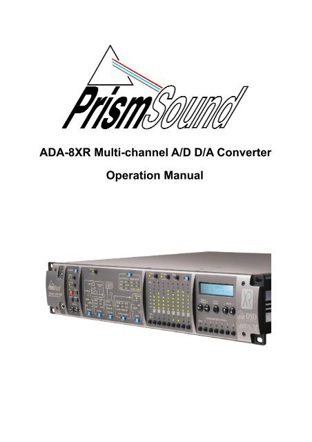
<strong>ADA</strong>-<strong>8XR</strong> <strong>Multi</strong>-<strong>channel</strong> A/D D/A <strong>Converter</strong><br />
<strong>Operation</strong> <strong>Manual</strong>
Prism Sound <strong>ADA</strong>-<strong>8XR</strong> <strong>Multi</strong>-<strong>channel</strong> A/D D/A <strong>Converter</strong> <strong>Operation</strong> <strong>Manual</strong> - Revision 1.00<br />
<strong>Operation</strong> <strong>Manual</strong> Revision History<br />
Rev Date Author Comments<br />
1.00 4 th December 2004 Ian Dennis Initial release with 2.00 firmware<br />
Support Contacts<br />
Prism Media Products Limited<br />
Prism Media Products Inc<br />
William James House<br />
21 Pine Street<br />
Cowley Road<br />
Rockaway<br />
Cambridge CB4 0WX NJ 07866<br />
UK<br />
USA<br />
Telephone: +44 1223 424988 Telephone: +1 973 983 9577<br />
Fax: +44 1223 425023 Fax: +1 973 983 9588<br />
Email:<br />
Web:<br />
tech.support@prismsound.com<br />
http://www.prismsound.com<br />
Or contact your local Prism Sound distributor as detailed on the website.<br />
Trademark Acknowledgements<br />
Digidesign, Pro Tools, Pro Tools 24|MIX, 888|24 I/O, Pro Tools|HD, 192 I/O, 96 I/O, SYNC I/O and DigiLink are<br />
trademarks of Digidesign, a division of Avid Technology Inc.<br />
Direct Stream Digital, DSD, MAC-DSD, SuperMAC and the DSD logo are trademarks of Sony Corporation.<br />
Super Audio CD, SACD and the SACD logo are joint trademarks of Sony Corporation and Philips Electronics N.V.<br />
All trademarks acknowledged<br />
© 2001-2004 Prism Media Products Limited. All rights reserved.<br />
This manual may not be reproduced in whole or part, in any medium, without the written<br />
permission of Prism Media Products Limited.<br />
In accordance with our policy of continual development, features and specifications are<br />
subject to change without notice.<br />
© Prism Media Products Limited, 2001-2004 Page 1.2
Prism Sound <strong>ADA</strong>-<strong>8XR</strong> <strong>Multi</strong>-<strong>channel</strong> A/D D/A <strong>Converter</strong> <strong>Operation</strong> <strong>Manual</strong> - Revision 1.00<br />
WARNING!<br />
TO PREVENT FIRE OR SHOCK HAZARD DO NOT EXPOSE<br />
THIS EQUIPMENT TO RAIN OR MOISTURE. DO NOT<br />
REMOVE THE COVER. NO USER-SERICEABLE PARTS<br />
INSIDE. REFER SERVICING TO QUALIFIED SERVICE<br />
PERSONNEL.<br />
Statements of Conformity<br />
This equipment has been tested and found to comply with the limits for a Class B digital device, pursuant to Part 15<br />
of the FCC Rules. These limits are designed to provide reasonable protection against interference in a residential<br />
area. This device generates and uses radio frequency energy and, if not installed and used in accordance with the<br />
instructions, may cause interference to radio or TV reception. If this unit does cause interference to radio or TV<br />
reception, please try to correct the interference by one or more of the following measures:<br />
a) Reorient or relocate the receiving antenna.<br />
b) Increase the separation between the equipment and the receiving antenna.<br />
c) Plug the equipment into an outlet on a different circuit from the receiver.<br />
d) If necessary, consult your dealer or an experienced radio or TV technician.<br />
CAUTION: Changes or modifications to this equipment not expressly approved by the manufacturer could void the<br />
user’s authority to operate this equipment.<br />
THIS DIGITAL APPARATUS MEETS ALL CLASS B LIMITS FOR RADIO NOISE EMISSIONS AS LAID DOWN IN<br />
THE RADIO INTERFERENCE REGULATIONS OF THE CANADIAN DEPARTMENT OF COMMUNICATIONS.<br />
CET APPAREIL NUMÉRIQUE RESPECTE TOUTES LES EXIGIENCES APPLICABLES AUX APPAREILS<br />
NUMÉRIQUES DE CLASSE B SUR LE BROUILLAGE RADIOELECTRIQUE EDICTE PAR LE MINISTERE DES<br />
COMMUNICATIONS DU CAN<strong>ADA</strong>.<br />
Prism Media Products Ltd hereby declares that this equipment conforms to the following standards:<br />
EN55103-1, environment category E4<br />
EN55103-2, environment category E4<br />
NOTE: The use of this equipment with non-shielded interface cabling is not recommended by the manufacturer and<br />
may result in non-compliance with one or more of the above directives. All coaxial connections should be made<br />
using a properly screened 75Ω cable with the screen connected to the outer of the connector at both ends. All XLR<br />
connections should use a screened twisted pair cable with the screen connected to pin 1 of the XLR connector at<br />
both ends. In the case of the digital XLR connections this cable should be of 110Ω impedance.<br />
© Prism Media Products Limited, 2001-2004 Page 1.3
Prism Sound <strong>ADA</strong>-<strong>8XR</strong> <strong>Multi</strong>-<strong>channel</strong> A/D D/A <strong>Converter</strong> <strong>Operation</strong> <strong>Manual</strong> - Revision 1.00<br />
Contents<br />
1 Introduction ............................................................................ 6<br />
1.1 Functionality ................................................................................................................ 6<br />
1.2 Modularity.................................................................................................................... 7<br />
1.3 Firmware Updates....................................................................................................... 7<br />
1.4 Organization of these <strong>Manual</strong>s ................................................................................... 7<br />
2 Getting Started ....................................................................... 8<br />
2.1 Connecting the <strong>ADA</strong>-<strong>8XR</strong> ........................................................................................... 8<br />
2.2 Configuring the <strong>ADA</strong>-<strong>8XR</strong> ........................................................................................... 8<br />
3 Layout ................................................................................... 10<br />
3.1 Front Panel................................................................................................................ 10<br />
3.2 Rear Panel ................................................................................................................ 11<br />
4 Philosophy of <strong>Operation</strong>...................................................... 12<br />
4.1 Two Paths ................................................................................................................. 12<br />
4.2 Menus or dedicated controls................................................................................... 12<br />
4.3 Monitor, Mimic, Meter and Menu Panels .................................................................. 12<br />
4.4 Two-<strong>channel</strong> Monitor................................................................................................. 13<br />
4.5 Configuration / Stores ............................................................................................... 13<br />
4.6 Warning conditions.................................................................................................... 14<br />
5 Control Panel <strong>Operation</strong> ...................................................... 15<br />
5.1 Mimic Panel............................................................................................................... 15<br />
5.1.1 Source box......................................................................................................... 15<br />
5.1.2 Decode box........................................................................................................ 16<br />
5.1.3 Process box ....................................................................................................... 17<br />
5.1.4 Dither/Encode box ............................................................................................. 17<br />
5.1.5 Dest box............................................................................................................. 18<br />
5.1.6 Sync Source/Sample Rate box.......................................................................... 18<br />
5.2 Meter Panel............................................................................................................... 20<br />
5.3 Monitor Panel ............................................................................................................ 21<br />
5.4 Menu Panel ............................................................................................................... 22<br />
6 Adjustments and Upgrades................................................. 23<br />
6.1 Changing the mains voltage or fuse ......................................................................... 23<br />
6.2 Adding I/O Modules................................................................................................... 24<br />
6.3 Upgrading the firmware............................................................................................. 24<br />
7 Technical Background ......................................................... 25<br />
7.1 Synchronization and jitter.......................................................................................... 25<br />
7.1.1 Background........................................................................................................ 25<br />
7.1.2 Why are good clocks so rare ........................................................................... 25<br />
7.1.3 Analysis of sampling jitter .................................................................................. 25<br />
7.1.4 Listening experience .......................................................................................... 26<br />
7.1.5 Synchronization and the <strong>ADA</strong>-<strong>8XR</strong>.................................................................... 26<br />
7.2 Extended sample rates and Split96 interfacing ........................................................ 26<br />
7.2.1 What are ‘extended’ sample rates ................................................................... 26<br />
7.2.2 What is the use of extended sample rates ...................................................... 27<br />
7.2.3 Interfacing extended sample rates..................................................................... 27<br />
7.2.4 Extended sample rates in the <strong>ADA</strong>-<strong>8XR</strong>............................................................ 28<br />
7.3 Wordlength, dithering and Prism Sound SNS (Super Noise Shaping) ..................... 28<br />
7.3.1 Truncation and dithering .................................................................................... 28<br />
7.3.2 Noise shaping .................................................................................................... 29<br />
7.3.3 Wordlength and the <strong>ADA</strong>-<strong>8XR</strong>........................................................................... 29<br />
7.4 Prism Sound MR-X and DRE encoding processes .................................................. 31<br />
7.4.1 Prism Sound MR-X ............................................................................................ 31<br />
7.4.2 Using Prism Sound MR-X with the <strong>ADA</strong>-<strong>8XR</strong>.................................................... 32<br />
7.4.3 Prism Sound DRE: ‘Dynamic Range Enhancement’ ......................................... 33<br />
7.4.4 Using Prism Sound DRE with the <strong>ADA</strong>-<strong>8XR</strong> ..................................................... 33<br />
7.5 Prism Sound Overkiller ............................................................................................. 34<br />
© Prism Media Products Limited, 2001-2004 Page 1.4
Prism Sound <strong>ADA</strong>-<strong>8XR</strong> <strong>Multi</strong>-<strong>channel</strong> A/D D/A <strong>Converter</strong> <strong>Operation</strong> <strong>Manual</strong> - Revision 1.00<br />
7.6 Sample-rate conversion and Prism Sound SSRC .................................................... 34<br />
7.7 References................................................................................................................ 35<br />
8 Specifications....................................................................... 36<br />
8.1 Physical ..................................................................................................................... 36<br />
8.2 Synchronization......................................................................................................... 36<br />
8.3 Monitor ...................................................................................................................... 37<br />
8.4 Meters ....................................................................................................................... 37<br />
8.5 DSP ........................................................................................................................... 37<br />
9 Glossary................................................................................ 38<br />
© Prism Media Products Limited, 2001-2004 Page 1.5
Prism Sound <strong>ADA</strong>-<strong>8XR</strong> <strong>Multi</strong>-<strong>channel</strong> A/D D/A <strong>Converter</strong> <strong>Operation</strong> <strong>Manual</strong> - Revision 1.00<br />
1 Introduction<br />
The <strong>ADA</strong>-<strong>8XR</strong> is the latest in the acclaimed range of Prism Sound ‘Dream’ A/D and D/A<br />
converters which have become widely regarded as the world’s best sounding converters.<br />
Whilst continuing the tried and trusted ‘no compromise’ design philosophy of previous ‘Dream’<br />
products, the Dream <strong>ADA</strong>-<strong>8XR</strong> adds a new dimension in flexibility, functionality and costeffectiveness:<br />
• Eight <strong>channel</strong>s of high-performance 24-bit A/D conversion;<br />
• Eight <strong>channel</strong>s of high-performance 24-bit D/A conversion;<br />
• Sample rates up to 192kHz;<br />
• Modular digital I/O options include popular interface standards and direct workstation<br />
connections;<br />
• Two-<strong>channel</strong> Monitor section follows <strong>channel</strong> pairs or a mix of all <strong>channel</strong>s;<br />
• Prism Sound ‘Overkiller’ progressive limiting of each A/D <strong>channel</strong>;<br />
• Prism Sound ‘Super-Noise Shaping’ on each <strong>channel</strong>;<br />
• Precise and repeatable software-controlled analogue input and output line-up levels;<br />
• Eight-<strong>channel</strong> assignable bargraph meter array with over-detection;<br />
• Renowned Prism Sound jitter-rejecting PLL technology and low-jitter master clock;<br />
• Flexible synchronization options, including sync to AES11, wordclock or video sync;<br />
• Flexible routing allows creation of D-D processing Paths for processing or format<br />
conversion;<br />
• Prism Sound ‘MR-X’ bit-splitting allows extended wordlengths and sample rates on 16-bit<br />
media;<br />
• Prism Sound ‘DRE’ allows extended wordlength performance on 16-bit stereo media;<br />
• Optional DSP expansion facility for extended processing features, including synchronous<br />
sample-rate conversion;<br />
• Modular architecture allows special configurations: e.g. 16-<strong>channel</strong> D/A or A/D unit;<br />
• Comprehensive store system for fast-access factory and user presets;<br />
• Unique ‘Access button’ layout combines flexibility of menus with speed of dedicated<br />
controls;<br />
• Modular architecture provides future-proofing: A/D conversion, D/A conversion, DSP, digital<br />
interfacing and utility hardware can all be individually upgraded;<br />
1.1 Functionality<br />
The <strong>ADA</strong>-<strong>8XR</strong> provides eight <strong>channel</strong>s of high-resolution, high-sample-rate A/D and D/A<br />
conversion with a variety of processing and interfacing functions, plus a two-<strong>channel</strong> Monitor<br />
with both analogue and digital outputs.<br />
A/D and D/A Paths can be independently synchronized at 32, 44.1, 48, 88.2, 96, 176.4 or<br />
192kHz sample rates. Sync sources can be Local, WCK, AES11 or DI (one of the digital<br />
inputs), and can be at a different rate from the Path’s sample rate if required. Wordlengths of<br />
16, 20 and 24 bits are supported.<br />
Digital output wordlength is managed by flat re-dithering, or by applying one of the family of<br />
industry-standard Prism Sound SNS noise shaping algorithms. Bit-splitting using the Prism<br />
Sound MR-X system (as implemented on the Prism Sound MR-2024T interface adapter and<br />
licensed equipment from other manufacturers) is built-in, so that 20-bit and 24-bit recordings<br />
at up to 96kHz can be made and replayed using 16-bit, low-sample-rate recorders. Encoding<br />
and decoding of Prism Sound’s DRE process (extended wordlength recording on 16-bit media<br />
without sacrificing tracks) is also included. Digital I/O for high sample rates can be in 1-wire<br />
or 2-wire (‘Split96’) format.<br />
Analogue inputs can be individually aligned in software for 0dBFS levels of +5dBu to +24dBu<br />
in 0.5dBu steps, with ±0.5dB trim in 0.05dB steps. The Prism Sound ‘Overkiller’ progressive<br />
limiter feature is selectable per analogue input <strong>channel</strong> to allow louder tape levels by control<br />
© Prism Media Products Limited, 2001-2004 Page 1.6
Prism Sound <strong>ADA</strong>-<strong>8XR</strong> <strong>Multi</strong>-<strong>channel</strong> A/D D/A <strong>Converter</strong> <strong>Operation</strong> <strong>Manual</strong> - Revision 1.00<br />
of transients. Analogue outputs can also be individually aligned for 0dBFS levels of +5dBu to<br />
+24dBu in 0.5dBu steps, with ±0.5dB trim in 0.05dB steps.<br />
A two-<strong>channel</strong> Monitor is provided which can be attached to either the A/D or D/A Path; it can<br />
monitor either adjacent-<strong>channel</strong> pairs, or a mix of any or all of the <strong>channel</strong>s, with individual<br />
gain and pan settings. The Monitor has both analogue (line and headphone) and digital<br />
outputs.<br />
Digital-to-digital Paths can be set up for dithering/noise-shaping, or MR-X/DRE<br />
encoding/decoding, and/or converting between different interface formats.<br />
1.2 Modularity<br />
The <strong>ADA</strong>-<strong>8XR</strong> is modular in respect of both its hardware and software. Throughout the life of<br />
the product, new software features and support for new hardware options will be added<br />
through firmware updates which will be distributed on disk and via the Internet.<br />
Although the standard <strong>ADA</strong>-<strong>8XR</strong> as summarised above provides eight <strong>channel</strong>s of A/D and<br />
eight <strong>channel</strong>s of simultaneous D/A conversion with a variety of available digital I/O options,<br />
many custom configurations are possible. For example, the <strong>ADA</strong>-<strong>8XR</strong> can be supplied as<br />
A/D-only or D/A-only at a cost saving, or with two A/D or D/A Modules for sixteen-<strong>channel</strong><br />
operation. A two-frame 8-in-24-out setup is a popular and cost-effective choice for DAW<br />
users.<br />
Another advantage of the modular construction of the <strong>ADA</strong>-<strong>8XR</strong> is that future improvements<br />
in technology can be incorporated; for example new A/D converter devices, D/A converter<br />
devices, DSP chips, digital I/O standards can all be accommodated by replacing only the<br />
relevant Module.<br />
1.3 Firmware Updates<br />
The <strong>ADA</strong>-<strong>8XR</strong> firmware is stored within the unit in a flash memory which can be updated from<br />
a floppy disk or from the Internet. Details of how to perform the upgrade are in section 6.3.<br />
1.4 Organization of these <strong>Manual</strong>s<br />
The <strong>ADA</strong>-<strong>8XR</strong> operators’ literature is organised as three separate volumes:<br />
• <strong>Operation</strong> <strong>Manual</strong> (this volume) which covers the general principles of operation;<br />
• Firmware Reference which provides operating details of the latest firmware revision;<br />
this volume can be updated in the event of a firmware upgrade;<br />
• Module Reference which contains information about all available analogue and<br />
digital I/O Modules; this volume can be updated to cover new I/O Modules;<br />
© Prism Media Products Limited, 2001-2004 Page 1.7
Prism Sound <strong>ADA</strong>-<strong>8XR</strong> <strong>Multi</strong>-<strong>channel</strong> A/D D/A <strong>Converter</strong> <strong>Operation</strong> <strong>Manual</strong> - Revision 1.00<br />
2 Getting Started<br />
This section is intended to get you going quickly, without the need to read the entire<br />
<strong>Operation</strong> <strong>Manual</strong>. This is quite feasible if your application is fairly ‘standard’; if not, you may<br />
need to refer to other parts of the manual to get exactly what you need.<br />
If your <strong>ADA</strong>-<strong>8XR</strong> is to be used with a direct workstation interface, such as Pro Tools, please<br />
refer to the appropriate ‘Getting Started’ section in the Module Reference (volume 3).<br />
2.1 Connecting the <strong>ADA</strong>-<strong>8XR</strong><br />
First, check that the line voltage setting matches your local voltage; if not change it by<br />
reorienting the voltage selector in the power inlet on the rear of the unit. Two ranges are<br />
selectable: 180-250VAC or 90-125VAC. Details of how to switch between ranges are in<br />
section 6.1.<br />
Connections to the analogue inputs and outputs are via panel-mounted XLR connectors.<br />
Connections to digital inputs and outputs may require the use of a breakout cable (supplied)<br />
according to the formats fitted to your unit. Direct connection to a workstation may require the<br />
use of the workstation manufacturer’s cable. Refer to the appropriate section in the Module<br />
Reference for connection details and example diagrams.<br />
Analogue Monitor outputs are on RCA (phono) sockets; stereo digital Monitor out is on BNC<br />
(RCA/phono adapter included); AES11 ref sync I/O are on XLRs; wordclock ref sync I/O are<br />
on BNCs; serial comms (jumpered for RS-232) is on DB9 male.<br />
Plug in the unit and switch on the power switch which is integral to the power inlet. The<br />
<strong>ADA</strong>-<strong>8XR</strong> should briefly light all LEDs, then settle into its default setup with the level screen<br />
displayed on the LCD display. The unit can thereafter be turned off and on using the<br />
‘Standby’ key in the top left-hand corner of the front panel.<br />
2.2 Configuring the <strong>ADA</strong>-<strong>8XR</strong><br />
The user-interface of the <strong>ADA</strong>-<strong>8XR</strong> is a ‘three-tier’ system. If your application is fairly<br />
standard, you will probably be able to load a ‘Factory Store’, and be up and running straight<br />
away. There may be a few changes which you need to make to the loaded Store, which you<br />
can most easily do using the blue ‘Access’ buttons to take you straight to the Menus you<br />
need. If your application is unusual in its details, you may need to navigate the Menu system<br />
manually.<br />
First, have a look at the available ‘standard’ Factory Stores at the end of the Firmware<br />
Reference. These apply to most non-workstation applications. If you’re using a dedicated<br />
Workstation I/O Module, look instead at the Factory Stores section for that Module in the I/O<br />
Module Reference. Hopefully one of the Factory Stores will be either exactly what you need,<br />
or close to it.<br />
Select the most appropriate Factory Store by pressing the ‘Bank’ button at the bottom left of<br />
the Menu Panel until the desired Bank of Stores is shown in the LCD display. Then press the<br />
desired Store number button. At this point, the name and number of the desired Store should<br />
be displayed, along with the message: “Load”. Press the ‘Enter/Accept’ key to load the<br />
Store.<br />
If the Store you loaded requires further modification, the easiest way to do this is to use the<br />
blue Access buttons which are distributed over the <strong>ADA</strong>-<strong>8XR</strong>’s Front Panel. The Access<br />
buttons on the Mimic Panel (block diagram) area are the most likely to be useful. Using the<br />
‘Path’ select button in the top left-hand corner of the Mimic Panel, choose the Path who’s<br />
© Prism Media Products Limited, 2001-2004 Page 1.8
Prism Sound <strong>ADA</strong>-<strong>8XR</strong> <strong>Multi</strong>-<strong>channel</strong> A/D D/A <strong>Converter</strong> <strong>Operation</strong> <strong>Manual</strong> - Revision 1.00<br />
settings you want to modify. Normally Path 1 is configured as the A/D Path and Path 2 as the<br />
D/A Path, although other variations are possible – check that you are dealing with the desired<br />
Path by observing the signal flow indicated by the LEDs on the Mimic Panel in each of the<br />
states of the ‘Path’ selector button.<br />
Choose the appropriate Access button to take you to the first parameter you want to alter.<br />
For example, if you want to change something to do with the analogue input of an A/D Path,<br />
press the Access button in the ‘Source’ box. This action takes the Menu Panel (with the LCD<br />
display) directly to the cluster of Menus which deal with the analogue inputs. Pressing the<br />
SOURCE Access button again moves to the next analogue-input-related Menu and so on, in<br />
a cyclic fashion. When you have found the Menu you want, you should be able to alter the<br />
desired parameter using the Menu keys (in combination with the Channel Select buttons at<br />
the bottom of the Meter Panel if the parameter must be altered per-<strong>channel</strong>).<br />
If you can’t find how to access the desired parameters, refer to the Firmware Reference. If<br />
the parameters are obscure, you may need to navigate the Menu system manually without<br />
the help of the Access buttons.<br />
Finally, you should be able to check the correct operation of the <strong>ADA</strong>-<strong>8XR</strong> in system by using<br />
the eight bargraph meters on the Meter Panel, and perhaps also the two-<strong>channel</strong> Monitor<br />
feature, which is controlled from the Monitor Panel at the left-hand side of the unit. Note that<br />
both of these Panels are also assignable to either of the two eight-<strong>channel</strong> Paths with their<br />
own [Path] selector buttons.<br />
© Prism Media Products Limited, 2001-2004 Page 1.9
Prism Sound <strong>ADA</strong>-<strong>8XR</strong> <strong>Multi</strong>-<strong>channel</strong> A/D D/A <strong>Converter</strong> <strong>Operation</strong> <strong>Manual</strong> - Revision 1.00<br />
3 Layout<br />
3.1 Front Panel<br />
The front panel of the <strong>ADA</strong>-<strong>8XR</strong> contains four divided panels, from left to right:<br />
The Monitor Panel controls and displays all parameters of the two-<strong>channel</strong> Monitor.<br />
The Mimic Panel controls and displays all parameters of the routing and processing of the two<br />
eight-<strong>channel</strong> audio Paths through the <strong>ADA</strong>-<strong>8XR</strong>.<br />
The Meter Panel contains eight LED bargraphs which can be switched to meter either of the<br />
two eight-<strong>channel</strong> Paths, as well as a row of Channel Select buttons, which are used to apply<br />
controls to one or more selected <strong>channel</strong>s, or to all eight <strong>channel</strong>s using the ‘All’ button.<br />
On the right-hand side is the Menu Panel, which contains the LCD display and navigation<br />
keys for the menu system, through which all parametric adjustments are made. Blue Access<br />
buttons, distributed over the other three panels, provide short-cuts into those parts of the<br />
menu system related to their positions. Below the menu controls are the buttons for the<br />
Configuration / Store system, which allows factory and user-defined setups to be instantly<br />
loaded.<br />
At the extreme left-hand side of the front panel are the ‘Standby’ key (which is used to switch<br />
the <strong>ADA</strong>-<strong>8XR</strong> in and out of Standby power mode) and, below, a headphone socket for the<br />
two-<strong>channel</strong> Monitor.<br />
© Prism Media Products Limited, 2001-2004 Page 1.10
Prism Sound <strong>ADA</strong>-<strong>8XR</strong> <strong>Multi</strong>-<strong>channel</strong> A/D D/A <strong>Converter</strong> <strong>Operation</strong> <strong>Manual</strong> - Revision 1.00<br />
3.2 Rear Panel<br />
The rear panel of the <strong>ADA</strong>-<strong>8XR</strong> is arranged, from left to right when viewed from the rear, as<br />
follows:<br />
The mains inlet comprises an inlet socket for the IEC mains lead (appropriate regional<br />
version, provided), mains switch, and two-way voltage selector and fuse holder. For details of<br />
how to change the voltage selector, see section 6.1.<br />
To the right of the mains inlet are two large Module Slots for Analogue I/O Modules. The<br />
upper slot is referred to as Analogue I/O Slot #1, or AIO1 in the front-panel legends and<br />
menus. Inputs on Analogue Module #1 are referred to as AI1, outputs as AO1. The lower<br />
slot is Analogue I/O Slot #2, with similar nomenclatures.<br />
To the right of the Analogue I/O Slots are two small Module Slots for Digital I/O Modules. The<br />
upper slot is referred to as Digital I/O Slot #1, or DIO1 in the front-panel legends and menus.<br />
Inputs on Digital Module #1 are referred to as DI1, outputs as DO1. The lower slot is Digital<br />
I/O Slot #2, with similar nomenclatures.<br />
On the extreme right-hand side is the Utility Module, which contains a variety of input and<br />
output connectors for Reference Sync, analogue and digital Monitor, and serial<br />
communications.<br />
Details of all available Analogue and Digital I/O Modules, including the Utility Module, are in<br />
the Module Reference.<br />
© Prism Media Products Limited, 2001-2004 Page 1.11
Prism Sound <strong>ADA</strong>-<strong>8XR</strong> <strong>Multi</strong>-<strong>channel</strong> A/D D/A <strong>Converter</strong> <strong>Operation</strong> <strong>Manual</strong> - Revision 1.00<br />
4 Philosophy of <strong>Operation</strong><br />
4.1 Two Paths<br />
The <strong>ADA</strong>-<strong>8XR</strong> has two Paths each comprising eight <strong>channel</strong>s; these are typically an A/D Path<br />
and a D/A Path (but not necessarily so). The Monitor, Mimic and Meter panels each have a<br />
‘Path’ selector button so that their function can be swapped between the Paths. The ‘Path’<br />
selector buttons on these panels are independent, so you can monitor one Path while<br />
metering the other, for instance. The Monitor and Meters can be positioned ‘Pre’ or ‘Post’ the<br />
Path’s Processing function (if any), but in systems without the Processing suite installed, or<br />
with it turned off, these buttons don’t change anything.<br />
4.2 Menus or dedicated controls<br />
The <strong>ADA</strong>-<strong>8XR</strong> has a novel operating philosophy. We were concerned that the unit should be<br />
simple to use, even though its flexibility and modularity mean that it has very many controls,<br />
and will have even more in the future.<br />
We know that nobody likes menus - it takes a long time to find what you need. On the other<br />
hand, a button and a display for everything wouldn’t fit on the front panel, and would be<br />
confusing - and we couldn’t add new features in later software releases.<br />
So the <strong>ADA</strong>-<strong>8XR</strong> control surface is based on four panels; from left to right the Monitor, Mimic,<br />
Meter and Menu panels (all alliteration absolutely accidental).<br />
4.3 Monitor, Mimic, Meter and Menu Panels<br />
In the Menu panel, you will find a huge menu (details of which are included in the<br />
accompanying Firmware Reference) and the Configuration/Store buttons. It is possible to do<br />
nearly anything through the menu system, but you have to know where to look. This is where<br />
the other panels come in.<br />
The Mimic panel shows a diagram of a ‘Path’ through the <strong>ADA</strong>-<strong>8XR</strong> - each Path is actually<br />
eight audio <strong>channel</strong>s in parallel, so the Mimic panel actually only shows one eighth of a Path.<br />
The A/D Path, for example, (usually Path 1) shows an analogue input, connected through<br />
some processing, past a monitoring and metering point, through some ‘encoding’ and out<br />
through a digital output. Naturally, there are countless settings which affect this Path buried<br />
in the menu system.<br />
On the Mimic panel are a selection of blue Access buttons, each one conveniently located in<br />
one of the functional areas of the Mimic. If you press an Access button, you immediately<br />
attract the attention of the Menu panel to the particular menu which controls that function (and<br />
the nearby blue LED lights to show that that is happening).<br />
Actually, there may be several menus which apply to that Access button; if the first menu isn’t<br />
the right one, press the Access button again and you can cycle round the small number of<br />
relevant menus. If you use the same menu a lot, don’t worry - next time you use that Access<br />
button, you go straight to the menu you were using last time you were in that Access group.<br />
The Monitor and Meter panels also have an Access button which are used to get to their parts<br />
of the menu system fast.<br />
In the Meter panel, under each <strong>channel</strong>’s meter, is a Channel Select button; normally, this is<br />
used to monitor that pair of <strong>channel</strong>s (or to select or deselect the <strong>channel</strong> if the Monitor is in<br />
© Prism Media Products Limited, 2001-2004 Page 1.12
Prism Sound <strong>ADA</strong>-<strong>8XR</strong> <strong>Multi</strong>-<strong>channel</strong> A/D D/A <strong>Converter</strong> <strong>Operation</strong> <strong>Manual</strong> - Revision 1.00<br />
Mix mode). But in menus where settings need to be made ‘per <strong>channel</strong>’, these buttons take<br />
on that function whilst that menu is selected.<br />
4.4 Two-<strong>channel</strong> Monitor<br />
Apart from its two eight-<strong>channel</strong> Paths, the <strong>ADA</strong>-<strong>8XR</strong> has a separate two-<strong>channel</strong> Monitor<br />
which can be assigned to either Path. It has a headphone output, as well as analogue and<br />
digital ‘line outputs’. It has the usual Cut, Invert, Swap and Mono functions, along with a<br />
volume control (which can be switched out if you want to use an external control for the line<br />
volume). Inserting the headphones can be made to mute the line outputs if required.<br />
The Monitor can be set to ‘Pairs’ or ‘Mix’ mode. In Pairs mode, it simply monitors adjacent<br />
pairs of <strong>channel</strong>s (odd to the left, even to the right) as selected by the Channel Select buttons.<br />
In Mix mode, a mix of any or all of the eight <strong>channel</strong>s in the Path can be built up, each with its<br />
own gain and pan. You can switch between separately adjusted mixes for each Path.<br />
4.5 Configuration / Stores<br />
These buttons are used to change the entire setup of the <strong>ADA</strong>-<strong>8XR</strong> between preset<br />
configurations for different tasks. There are four ‘Banks’ each containing six entire Stores of<br />
the <strong>ADA</strong>-<strong>8XR</strong> state, thus a total of 24 stores are available. Each store can have a name of up<br />
to 16 characters to ease identification.<br />
Pressing either the ‘Bank’ button or one of the Store number buttons (‘1’..’6’) attracts the<br />
attention of the LCD display to the Configuration/Store system. The name of the currentlyselected<br />
Store is displayed on the top line, with the Bank/Store number shown below. The<br />
various stores can be previewed by pressing the Store number buttons (‘1’..’6’), and the Bank<br />
can be advanced by pressing the Bank button. The currently-selected Store’s LED flashes.<br />
The LCD is returned to it’s normal operation by re-pressing the flashing Store button (‘1’..’6’),<br />
or by pressing the ‘Menu’ keys (‘↑’ or ‘↓’) or by pressing a blue Access button. Normal<br />
operation is also resumed by the expiry of the menu timeout, if enabled.<br />
The previewed store can be adopted (‘loaded’), unless empty, by pressing Enter/Accept.<br />
Alternatively, it can be over-written (‘saved’) or cleared by using the ‘Select/Change’ keys (‘←’<br />
or ‘→’) to select the required function, followed by ‘Enter/Accept’. Clearing a Store requires a<br />
confirmation step; saving requires the store name to be confirmed or edited, followed by a<br />
confirmation step.<br />
When a Store has been loaded, that Store’s button remains illuminated (until any settings are<br />
manually changed) to indicate that the Store is current.<br />
At the time of delivery, some of the Stores in the first Banks contain ‘factory’ preset stores<br />
covering a range of basic setups (depending on the I/O Modules fitted to the unit), and the<br />
remaining Stores are empty. However, the factory-programmed stores are essentially the<br />
same as others in that they can be user-programmed if required. If, after reprogramming, it is<br />
desired to return these Stores to their factory default settings, this can be achieved through<br />
the Preferences menu. The Factory Default Stores loaded will reflect the I/O Modules fitted at<br />
the time of the reload.<br />
The user can select whether or not analogue I/O line-up gains and trims, and the state of the<br />
Monitor are to be recalled with Stores, or not, by using submenus within Preferences.<br />
© Prism Media Products Limited, 2001-2004 Page 1.13
Prism Sound <strong>ADA</strong>-<strong>8XR</strong> <strong>Multi</strong>-<strong>channel</strong> A/D D/A <strong>Converter</strong> <strong>Operation</strong> <strong>Manual</strong> - Revision 1.00<br />
4.6 Warning conditions<br />
It is possible to set operating parameters in the <strong>ADA</strong>-<strong>8XR</strong> which are mutually conflicting, or<br />
which cannot be met for other reasons. For instance if the analogue outputs are assigned to<br />
both Paths, or if an external reference sync is specified but is not connected, then the<br />
<strong>ADA</strong>-<strong>8XR</strong> must deal with the resulting situation.<br />
In these cases, warnings are generated. Warnings are indicated by a flashing LED, and<br />
possibly the solid illumination of an additional LED. For example, in the case of an<br />
unconnected external reference sync, local sync will be automatically substituted and this<br />
state will be shown by the ‘Local’ LED being lit and the LED of the intended external sync<br />
being flashed.<br />
In general, solidly lit LEDs indicate what is actually happening, and flashing LEDs indicate<br />
what has been requested but cannot be implemented.<br />
If any warnings are active, a row of flashing exclamation marks are shown at the right-hand<br />
side of the LCD display when it is in the default ‘level’ display mode (‘!!!→’). Pressing the<br />
right ‘Select/Change’ key (‘→’) enters the Warnings screen, where all the current warnings are<br />
flashed in turn on the bottom line of the LCD. To return to the normal ‘Level’ display, press<br />
the left ‘Select/Change’ key (‘←’).<br />
© Prism Media Products Limited, 2001-2004 Page 1.14
Prism Sound <strong>ADA</strong>-<strong>8XR</strong> <strong>Multi</strong>-<strong>channel</strong> A/D D/A <strong>Converter</strong> <strong>Operation</strong> <strong>Manual</strong> - Revision 1.00<br />
5 Control Panel <strong>Operation</strong><br />
5.1 Mimic Panel<br />
The Mimic panel is the key to understanding and controlling the flow of signals through the<br />
<strong>ADA</strong>-<strong>8XR</strong>. At any one time, it shows the flow of signals through one of the <strong>ADA</strong>-<strong>8XR</strong>’s two<br />
Paths, from the assigned source ports, through any assigned processing functions, through to<br />
the assigned destination ports.<br />
The ‘Path’ selector button in the top left-hand corner of the panel assigns its function to either<br />
Path 1 or Path 2. Path 1 is usually the A-D Path, and Path 2 the D-A Path, in most standard<br />
A/D-D/A configurations, but this is flexible.<br />
The remaining controls and indicators on the Mimic Panel are arranged in an array of<br />
functionally separate boxes, as described below. Each of these functional boxes has a blue<br />
Access button, which takes the <strong>ADA</strong>-<strong>8XR</strong>’s menu system directly to the small group of menus<br />
which apply to that box’s function; pressing the Access button repeatedly cycles through the<br />
menus specific to that box. For details of these functions, see the Firmware Reference. Note<br />
that the menus reached by pressing the Access buttons can also be reached (but not so<br />
quickly or conveniently) by navigating the menu system in the normal way. An Access<br />
button’s LED is lit whenever one of its associated menus is active, even if that menu was not<br />
activated by the Access button.<br />
5.1.1 Source box<br />
The Source box indicates which port(s) are assigned as the inputs to the selected Path, and<br />
displays other input-related parameters. The Source box’s Access button attracts the<br />
attention of the Menu panel immediately to the small group of menus that control sourcerelated<br />
parameters. These include assignment of the source ports themselves, adjustment of<br />
analogue input gains (if an analogue source port is assigned) etc. For details of these menus,<br />
see the Firmware Reference.<br />
The green LEDs at the left-hand side of the box show which input ports have been assigned<br />
to the Path. These comprise Analogue Module Slot 1 or 2 inputs, or Digital Module Slot 1 or 2<br />
inputs. The ‘Split96’ indicators show when digital inputs are being used in a ‘two wire’ mode<br />
whereby a single high-rate <strong>channel</strong> is being carried on a normally-two-<strong>channel</strong> interface.<br />
© Prism Media Products Limited, 2001-2004 Page 1.15
Prism Sound <strong>ADA</strong>-<strong>8XR</strong> <strong>Multi</strong>-<strong>channel</strong> A/D D/A <strong>Converter</strong> <strong>Operation</strong> <strong>Manual</strong> - Revision 1.00<br />
Note that more than one source LED can be lit; this might happen when two Digital I/O<br />
Modules are ‘cascaded’ in Split96 mode to provide all eight inputs, or when the ‘Input<br />
Selection Mode’ is set to ‘Channel’, allowing each <strong>channel</strong>’s input to be chosen from more<br />
than one assigned port (see the Firmware Reference). A source LED which is flashing<br />
indicates that a selection has been requested which the <strong>ADA</strong>-<strong>8XR</strong> firmware cannot<br />
accomplish, for example a source port may have been assigned which has already been<br />
assigned to the other Path.<br />
The ‘Overkiller’ LED shows that one or more <strong>channel</strong>s in the Path has its Overkiller<br />
(progressive analogue limiter) switched on. For more information about the operation and<br />
application of the Overkiller, see section 7.5.<br />
The ‘Mic’ and ‘+48V’ LEDs only apply to Analogue Input Modules with a mic-pre facility, and<br />
indicate that one or more <strong>channel</strong>s in the Path have the mic-pre selected, and the phantom<br />
power turned on respectively.<br />
5.1.2 Decode box<br />
The Decode box indicates the wordlength of the Path’s digital inputs (if digital inputs are<br />
assigned), and also any decode algorithms which are in use. The Decode box’s Access<br />
button attracts the attention of the Menu panel immediately to the small group of menus that<br />
control the available decoding algorithms. For details of these menus, see the Firmware<br />
Reference.<br />
The ‘MR-X’ LED shows that the input port is being decoded from the Prism Sound MR-X<br />
format, which is a word-mapping scheme whereby, for example, a multi-<strong>channel</strong> digital<br />
recorder can be used to record longer wordlengths and/or higher sample rates than its native<br />
format by sacrificing tracks. ‘MR-X 16 ’ is the variant of this format for recorders (or data<br />
<strong>channel</strong>s) with a maximum 16-bit wordlength, whereas ‘MR-X 20 ’ is used for 20-bit media<br />
where less track sacrificing results. The ‘[20b]’ LED shows that ‘MR-X 20 ’ decoding is taking<br />
place, whereas the ‘MR-X’ LED without the ‘[20b]’ LED shows ‘MR-X 16 ’ decoding. The Prism<br />
Sound MR-X encoding scheme is described in detail in section 7.4.<br />
The ‘DRE’ LED shows that one or more of the input <strong>channel</strong>s are being decoded from the<br />
Prism Sound DRE (Dynamic Range Enhancement) format, which is a coding scheme to allow<br />
extended wordlengths to be recorded on a medium (or passed down a digital <strong>channel</strong>)<br />
WITHOUT sacrificing tracks. ‘DRE 16 ’ is the variant of this format for recorders (or data<br />
<strong>channel</strong>s) with a maximum 16-bit wordlength, whereas ‘DRE 20 ’ is used for 20-bit media. Note,<br />
however, that the decoding algorithm is common for DRE 16 and DRE 20 data, so it is not<br />
necessary to distinguish which is to be decoded. The Prism Sound DRE encoding scheme is<br />
described in detail in section 7.4.<br />
The green LEDs at the left-hand side of the box show the effective input wordlength of the<br />
input <strong>channel</strong>s. Note that the wordlength AFTER any decoding is indicated, i.e. a 24-bit<br />
signal being recovered from a 16-bit MR-X tape is indicated as 24-bits. The indication is<br />
made by detecting how many of the low-order data bits are held at zero, rather than by any<br />
other means. Note that multiple wordlength LEDs may be lit if different input wordlengths<br />
occur simultaneously on different <strong>channel</strong>s.<br />
© Prism Media Products Limited, 2001-2004 Page 1.16
Prism Sound <strong>ADA</strong>-<strong>8XR</strong> <strong>Multi</strong>-<strong>channel</strong> A/D D/A <strong>Converter</strong> <strong>Operation</strong> <strong>Manual</strong> - Revision 1.00<br />
5.1.3 Process box<br />
The Process box indicates whether any of the Path’s <strong>channel</strong>s have any functions of the<br />
Processing Suite activated. The processing Suite is a range of signal processing functions<br />
which are available if the DSP Expansion Module is fitted inside the <strong>ADA</strong>-<strong>8XR</strong>. The Process<br />
box’s Access button attracts the attention of the Menu panel immediately to the group of<br />
menus that control the Processing Suite if it is available (otherwise an explanatory message is<br />
displayed). For details of these menus, see the Firmware Reference.<br />
The ‘Patch’ LED is lit to indicate that some cross-<strong>channel</strong> patching or mixing is selected. The<br />
‘Process’ LED shows that signal processing functions are active. Otherwise, the ‘Bypass’<br />
LED confirms that no patching or processing is enabled.<br />
5.1.4 Dither/Encode box<br />
The Dither/Encode box indicates the wordlength of the Path’s digital outputs (if digital outputs<br />
are assigned), and also any encode algorithms which are in use. The Dither/Encode box’s<br />
Access button attracts the attention of the Menu panel immediately to the small group of<br />
menus that control output wordlength and encoding algorithms. For details of these menus,<br />
see the Firmware Reference.<br />
The column of green LEDs in the middle of the box show the wordlength of the digital audio<br />
<strong>channel</strong>s being output. More than one of these LEDs might be illuminated if more than one<br />
wordlength range has been selected for different output <strong>channel</strong>s of the Path. The ‘SNS’ LED<br />
to the left is illuminated if any of the <strong>channel</strong>s has has wordlength reduction using the Prism<br />
Sound Super Noise Shaping algorithm selected. The ‘Flat’ LED is lit if any of the Path’s<br />
<strong>channel</strong>s have only flat dither selected. The Prism Sound Super Noise Shaping process is<br />
described in detail in section 7.3.<br />
The ‘Auto’ LED is lit to indicate that ‘Auto Dither Defeat’ is active. Auto Dither Defeat is an<br />
algorithm which prevents unnecessary or undesirable dithering or noise shaping being<br />
applied to the <strong>channel</strong>s of a digital-to-digital Path. This happens in one of two situations.<br />
Firstly, if the incoming wordlength is less than or equal to the desired output wordlength, it is<br />
unnecessary to add further dither or noise shaping, since no truncation of the wordlength is<br />
implied. To add further dither or noise shaping would merely increase the noise floor of the<br />
signal without benefit. The second situation occurs if the incoming audio data is ‘digital black’<br />
i.e. all the audio data bits are zero. In this situation, it is undesirable to add dither to the<br />
outgoing audio since ‘black-in-black-out’ operation is useful when compiling tracks etc. Some<br />
older editing systems require ‘black-in-black-out’ behaviour to recognise track boundaries.<br />
Note that digital black input is assumed after 10000 consecutive zero samples have been<br />
received, and is cancelled immediately on receipt of a non-zero sample. Note that, in fact, the<br />
second situation is really a subset of the first since black audio data has essentially zero-bit<br />
wordlength. The Auto LED is lit when ALL active <strong>channel</strong>s in the Path are in Auto Dither<br />
Defeat mode.<br />
The ‘MR-X’ LED shows that the output port is being encoded using the Prism Sound MR-X<br />
format, which is a word-mapping scheme whereby, for example, a multi-<strong>channel</strong> digital<br />
recorder can be used to record longer wordlengths and/or higher sample rates than its native<br />
format by sacrificing tracks. ‘MR-X 16 ’ is the variant of this format for recorders (or data<br />
<strong>channel</strong>s) with a maximum 16-bit wordlength, whereas ‘MR-X 20 ’ is used for 20-bit media<br />
where less track sacrificing results. The ‘[20b]’ LED shows that ‘MR-X 20 ’ encoding is taking<br />
place, whereas the ‘MR-X’ LED without the ‘[20b]’ LED shows ‘MR-X 16 ’ encoding. The Prism<br />
Sound MR-X encoding scheme is described in detail in section 7.4.<br />
The ‘DRE’ LED shows that one or more of the input <strong>channel</strong>s are being encoded using the<br />
Prism Sound DRE (Dynamic Range Enhancement) format, which is a coding scheme to allow<br />
extended wordlengths to be recorded on a medium (or passed down a digital <strong>channel</strong>)<br />
© Prism Media Products Limited, 2001-2004 Page 1.17
Prism Sound <strong>ADA</strong>-<strong>8XR</strong> <strong>Multi</strong>-<strong>channel</strong> A/D D/A <strong>Converter</strong> <strong>Operation</strong> <strong>Manual</strong> - Revision 1.00<br />
WITHOUT sacrificing tracks. ‘DRE 16 ’ is the variant of this format for recorders (or data<br />
<strong>channel</strong>s) with a maximum 16-bit wordlength, whereas ‘DRE 20 ’ is used for 20-bit media. The<br />
‘[20b]’ LED shows that ‘DRE 20 ’ encoding is taking place, whereas the ‘DRE’ LED without the<br />
‘[20b]’ LED shows ‘DRE 16 ’ encoding. The Prism Sound DRE encoding scheme is described<br />
in detail in section 7.4.<br />
5.1.5 Dest box<br />
The Dest (Destination) box indicates which port(s) are assigned as the outputs to the selected<br />
Path, and displays whether digital output ports are operating in Split96 (two-wire) high-rate<br />
mode. The Destination box’s Access button attracts the attention of the Menu panel<br />
immediately to the small group of menus that control destination-related parameters. These<br />
include assignment of the destination ports themselves, adjustment of analogue output gains<br />
(if an analogue destination port is assigned) etc. For details of these menus, see the<br />
Firmware Reference.<br />
The green LEDs at the right-hand side of the box show which output ports have been<br />
assigned to the Path. These comprise Analogue Module Slot 1 or 2 outputs, or Digital<br />
Module Slot 1 or 2 outputs. The ‘Split96’ indicators show when digital outputs are being used<br />
in a ‘two wire’ mode whereby a single high-rate <strong>channel</strong> is carried on a normally-two-<strong>channel</strong><br />
interface. Note that more than one destination LED can be lit; this might happen when two<br />
Digital I/O Modules are ‘cascaded’ in Split96 mode to provide all eight outputs, or simply when<br />
multiple output ports have been assigned to the Path (as ‘parallel’ outputs). A destination<br />
LED which is flashing indicates that a selection has been requested which the <strong>ADA</strong>-<strong>8XR</strong><br />
firmware cannot accomplish, for example a destination port may have been assigned which<br />
has already been assigned to the other Path.<br />
5.1.6 Sync Source/Sample Rate box<br />
The Sync Source/Sample Rate box indicates the synchronization state of the Path. Its<br />
Access button attracts the attention of the Menu panel immediately to the small group of<br />
menus that control the various synchronization options. For details of these menus, see the<br />
Firmware Reference.<br />
The six LEDs on the left-hand side of the box indicate the selected synchronization source.<br />
‘Local’ is the <strong>ADA</strong>-<strong>8XR</strong>’s internal crystal reference, ‘WCK’, ‘AES’ and ‘Video’ refer to various<br />
synchronization input connectors on the Utility Module (at the right-hand side of the rear panel<br />
of the <strong>ADA</strong>-<strong>8XR</strong> when viewed from the back). ‘WCK’ (wordclock) is a TTL-level square wave,<br />
with its rising edge indicating the reference’s sample instant – this is connected to the BNC ref<br />
sync input of the Utility Module. ‘AES’ is an AES11 (‘DARS’) or AES3 format reference signal<br />
connected to the XLR ref sync input of the Utility Module, or an AES3-id format reference<br />
signal connected to the BNC ref sync input of the Utility Module. ‘Video’ is an analogue video<br />
signal (PAL, SECAM or NTSC) applied to the BNC ref sync input of the Utility Module. ‘DI1’<br />
and ‘DI2’ are ref sync inputs from the Digital I/O Module fitted in the upper or lower DIO slot<br />
respectively. Refer to the Module Reference for more information about the Utility Module and<br />
its connections.<br />
The six LEDs on the right-hand side of the box indicate the Path’s sample rate. The<br />
combination of the ‘32k’, ‘44k1’ and ‘48k’ LEDs, along with the multiplier LEDs for ‘x2’ and ‘x4’<br />
allow for display of standard audio sample rates between 32kHz and 192kHz. Note that<br />
availability of rates may depend of which I/O Modules and firmware version are installed in<br />
your unit. See the Module Reference for details of the capabilities of current I/O Modules.<br />
The ‘=Ext’ LED is lit whenever the Path’s nominal sample rate has been set to follow that of<br />
the selected external sync source. It is important to note that the <strong>ADA</strong>-<strong>8XR</strong> does not insist on<br />
this: it is possible to select a different sample-rate from that of the designated reference sync.<br />
For example you could select an external Wordclock as a Path’s sync source, and also<br />
© Prism Media Products Limited, 2001-2004 Page 1.18
Prism Sound <strong>ADA</strong>-<strong>8XR</strong> <strong>Multi</strong>-<strong>channel</strong> A/D D/A <strong>Converter</strong> <strong>Operation</strong> <strong>Manual</strong> - Revision 1.00<br />
specify 48kHz explicitly as the desired sample rate. In this case, the external wordclock<br />
frequency is continually measured by the <strong>ADA</strong>-<strong>8XR</strong>, and an assessment is made as to<br />
whether it is within an acceptable tolerance of a standard sample rate and, if so, what the rate<br />
is. If the rate of the Wordclock is, say, close to 44.1kHz then the <strong>ADA</strong>-<strong>8XR</strong> will assume it to<br />
be the ‘house 44.1kHz’ and will use it to sync the Path, BUT THE PATH WILL STILL RUN AT<br />
48kHz or, more precisely, at 480/441 times the reference rate. In this case, the ‘=Ext’ LED<br />
would not be lit. If it is desired that the Path’s sample rate should always reflect the sample<br />
rate of the ref sync, then ‘=Ext’ should be selected in the sample rate menu. For more details<br />
of these menus, see the Firmware Reference.<br />
It is not uncommon to see flashing LEDs in the Sync Source/Sample Rate box. A flashing<br />
LED indicates a requested state which could not be met. For example, if an external AES<br />
reference was selected but no such ref sync input is detected by the <strong>ADA</strong>-<strong>8XR</strong>, it substitutes<br />
a local clock reference automatically, lights the ‘Local’ LED and flashes the ‘AES’ LED.<br />
© Prism Media Products Limited, 2001-2004 Page 1.19
Prism Sound <strong>ADA</strong>-<strong>8XR</strong> <strong>Multi</strong>-<strong>channel</strong> A/D D/A <strong>Converter</strong> <strong>Operation</strong> <strong>Manual</strong> - Revision 1.00<br />
5.2 Meter Panel<br />
The Meter Panel fulfils a few different <strong>channel</strong>-related functions. First and most importantly it<br />
provides eight bargraph meters which can be switched to display the audio levels on all eight<br />
<strong>channel</strong>s of either Path through the <strong>ADA</strong>-<strong>8XR</strong>. Various peak-hold and overload modes can<br />
be selected within the group of menus reached from the blue Access button. Note also that<br />
numerical metering of the selected <strong>channel</strong> or <strong>channel</strong> pair is normally displayed on the Level<br />
Screen (the ‘home’ screen of the Menu display).<br />
The ‘Path’ selector button in the top left-hand corner of the panel assigns the panel’s function<br />
to either Path 1 or Path 2. Path 1 is usually the A-D Path, and Path 2 the D-A Path, in most<br />
standard A-D/D-A configurations, but this is flexible. The ‘Pre Post’ button moves the<br />
metering position before or after the signal Processing block of the selected Path.<br />
The ‘Hold’ button enables or disables an indefinite bargraph peak-hold function, which also<br />
affects the numerical meters on the ‘home’ screen of the menu display.<br />
Below the bargraphs are a row of per-<strong>channel</strong> ‘Alert’ LEDs. These provide warning of various<br />
notable conditions occuring on the corresponding <strong>channel</strong> of the selected Path. These<br />
include digital input lock-status, analogue input overkiller action etc. The functions can be<br />
multiply selected in the appropriate menu (also reached from the Meter Panel Access button)<br />
so that the LED represents an ‘OR’ function of the selected functions.<br />
The Channel Select buttons, and the ‘All’ button are used in conjunction with certain <strong>channel</strong>specific<br />
menus, as described in the Module Reference.<br />
© Prism Media Products Limited, 2001-2004 Page 1.20
Prism Sound <strong>ADA</strong>-<strong>8XR</strong> <strong>Multi</strong>-<strong>channel</strong> A/D D/A <strong>Converter</strong> <strong>Operation</strong> <strong>Manual</strong> - Revision 1.00<br />
5.3 Monitor Panel<br />
The Monitor Panel controls the <strong>ADA</strong>-<strong>8XR</strong>’s two-<strong>channel</strong><br />
monitor.<br />
The Monitor drives both analogue and digital line outputs,<br />
which are situated on the Utility Panel on the rear of the<br />
unit. The analogue outputs also drive a headphone<br />
socket on the front. For further details see the Utility<br />
Module section in the I/O Modules section.<br />
The Monitor can be fed from either Path 1 or Path 2, as<br />
selected by the ‘Path’ selector button, either pre- or postthe<br />
Path’s processing section (where available) as<br />
selected by the ‘Pre Post’ button. Note that the audio<br />
output of the Monitor is controlled directly by these<br />
buttons; the equivalent buttons on other Panels only<br />
assign the Panels’ display.<br />
The ‘Cut’ button mutes the Monitor, its LED flashing red to<br />
indicate the muted state. The ‘Invert’ button phase-inverts<br />
BOTH of the Monitor’s output <strong>channel</strong>s when the orange LED is lit. The ‘Mono’ button causes<br />
the two Monitor <strong>channel</strong>s to be mixed together at both outputs when its LED is lit. The ‘Swap’<br />
button exchanges the Monitor’s A and B <strong>channel</strong> outputs when its LED is lit.<br />
A volume control is available if required, although this can be defeated from within the Monitor<br />
options menus.<br />
The blue Access button at the top of the panel causes the menu system to enter a small<br />
range of menus which apply to the two-<strong>channel</strong> Monitor. These menus control various<br />
auxiliary functions such as analogue line-up level, headphone-cut, volume control<br />
enable/disable etc., as well as allowing selection of the Monitor operating mode:<br />
In ‘Pairs’ mode, the adjacent-<strong>channel</strong> pairs are monitored, whereas in ‘Mixed’ mode, a mix of<br />
any of the Path’s <strong>channel</strong>s can be created, each with its own gain and pan setting. Separate<br />
mixes are retained for each Path, which are selected when that Path is monitored.<br />
For full details of the Monitor-related menus, see the Firmware Reference.<br />
© Prism Media Products Limited, 2001-2004 Page 1.21
Prism Sound <strong>ADA</strong>-<strong>8XR</strong> <strong>Multi</strong>-<strong>channel</strong> A/D D/A <strong>Converter</strong> <strong>Operation</strong> <strong>Manual</strong> - Revision 1.00<br />
5.4 Menu Panel<br />
The Menu Panel provides manual<br />
control and inspection of all the<br />
<strong>ADA</strong>-<strong>8XR</strong>’s operating parameters, and<br />
also contains the Configuration/Stores<br />
buttons for loading and saving setups<br />
of the <strong>ADA</strong>-<strong>8XR</strong>.<br />
The operation of the Menu system is<br />
detailed in the Firmware Reference. In<br />
general, the ‘Menu’ keys (‘↑’ and ‘↓’)<br />
are used to navigate up and down<br />
through the different menus at a<br />
particular level, the ‘Select/Change’<br />
keys (‘←’ and ‘→’) are used to select<br />
different values for the parameter in the<br />
current menu, and the ‘Enter/Accept’<br />
key is used to confirm the new setting<br />
or to descend to a lower menu level.<br />
Note that certain numeric parameters (such as analogue line-up levels) change dynamically<br />
with the operation of the ‘←’ and ‘→’ keys, and do not need to be confirmed with<br />
‘Enter/Accept’.<br />
For most operations, it is not necessary to navigate to the desired menu using the ‘Menu’<br />
keys (‘↑’ and ‘↓’) since the blue Access buttons in the other panels jump immediately to the<br />
menu or menus which apply to that area of the front panel. Where more than one menu is<br />
associated with an Access button, repeated pressing of that Access button cycles through<br />
them. The first press of any Access button jumps immediately to the last menu which was<br />
accessed in the associated group, so repeated access to a common menu becomes a onebutton<br />
operation.<br />
The Configuration/Stores buttons provide access to a store system of 24 stores, arranged as<br />
four banks of six stores each. All of these stores are user-configurable, although some of<br />
them initially contain factory default stores. Detailed description of the operation of the store<br />
system is also contained in the Firmware Reference.<br />
Pressing one of the numbered store buttons causes the name of that store to be shown in the<br />
LCD display, along with an invitation to load (recall) it, and that store can then be loaded by a<br />
single press of the ‘Enter/Accept’ key. The ‘Bank’ button cycles around the four banks of<br />
stores.<br />
To save (overwrite) a store with the current settings of the <strong>ADA</strong>-<strong>8XR</strong>, press the ‘→’ key, at<br />
which point an invitation to save is displayed after which ‘Enter/Accept’ begins the saving<br />
sequence of operations, which include the opportunity to enter a 16-character name of your<br />
choice, or to abort the operation.<br />
A further press of the ‘→’ key presents an invitation to clear (erase) the selected store.<br />
If the selected store is already empty, only the saving operation is possible.<br />
It is possible to ‘Reload factory stores’, as described in the Firmware Reference. This causes<br />
the <strong>ADA</strong>-<strong>8XR</strong> to generate a number of useful default stores based on the I/O Modules fitted,<br />
and store them in certain locations. Any manually-altered stores held in these locations are<br />
then overwritten, but all other stores remain intact.<br />
© Prism Media Products Limited, 2001-2004 Page 1.22
Prism Sound <strong>ADA</strong>-<strong>8XR</strong> <strong>Multi</strong>-<strong>channel</strong> A/D D/A <strong>Converter</strong> <strong>Operation</strong> <strong>Manual</strong> - Revision 1.00<br />
6 Adjustments and Upgrades<br />
The <strong>ADA</strong>-<strong>8XR</strong> mainframe has no need for any physical calibrations or jumpers; such<br />
calibrations as are necessary are managed in software. This is generally also true of the I/O<br />
Modules, but any user-adjustments that might apply are detailed in the Module Reference.<br />
6.1 Changing the mains voltage or fuse<br />
The mains (line) fuse and the mains voltage selector are carried within the IEC inlet on the<br />
rear of the <strong>ADA</strong>-<strong>8XR</strong>. The required fuse is a 2AT 20x5mm type. The voltage selector has<br />
two positions: ‘115V’ covers the range 90VAC to 130VAC, and ‘230V’ covers the range<br />
180VAC to 260VAC. The diagram below shows how to replace the fuse or change the<br />
voltage selection.<br />
Lever up the voltage selector / fuse holder cover<br />
by inserting a small, flat-bladed screwdriver into<br />
the slot as shown. Remove the red plastic holder.<br />
If replacing the fuse, use a 2AT 20mmx5mm type<br />
and, having placed it in the same location as the<br />
old fuse, replace the red plastic holder in the same<br />
orientation as before (with the selected voltage<br />
AWAY from the switch) and close the cover.<br />
To change the mains voltage selection, orient the red plastic holder with the desired voltage<br />
uppermost as shown in the diagram below. It is necessary to swap the positions of the fuse<br />
and a small metal clip on the opposite side of the holder. The correct side and location for<br />
each is shown in the diagram. Replace the red plastic holder in the new orientation (with the<br />
selected voltage AWAY from the switch) and close the cover. Check that the desired voltage<br />
is visible through the window. Note that unless the holder is inserted in the right orientation to<br />
match the positioning of the fuse and clip, the cover cannot be fully closed.<br />
© Prism Media Products Limited, 2001-2004 Page 1.23
Prism Sound <strong>ADA</strong>-<strong>8XR</strong> <strong>Multi</strong>-<strong>channel</strong> A/D D/A <strong>Converter</strong> <strong>Operation</strong> <strong>Manual</strong> - Revision 1.00<br />
6.2 Adding I/O Modules<br />
WARNING: It is NOT necessary to remove the top cover of the <strong>ADA</strong>-<strong>8XR</strong> to<br />
add or remove I/O Modules. Removal of the top cover with the mains supply<br />
connected presents a risk of electric shock.<br />
NOTE: Inserting or removing I/O Modules should be carried out with the power<br />
disconnected from the <strong>ADA</strong>-<strong>8XR</strong>. Failure to do this may result in damage to the<br />
<strong>ADA</strong>-<strong>8XR</strong>, the I/O Module or both.<br />
NOTE: To protect from static damage, I/O Modules are supplied in anti-static<br />
packaging. When removed from this packaging, I/O Modules should be handled only<br />
by their metal end-plates. The packaging should be retained, and Modules removed<br />
from the frame should be stored in it.<br />
To decide on the location of a new I/O Module, refer to the diagram of the <strong>ADA</strong>-<strong>8XR</strong> rear<br />
panel in section 3.2. When viewed from the rear, the analogue I/O (AIO) slots are the larger<br />
castellated panels on the left (AIO1 above, AIO2 below) and the digital I/O (DIO) slots are the<br />
smaller castellated panels on the right (DIO1 above, DIO2 below).<br />
In general, the <strong>ADA</strong>-<strong>8XR</strong> software regards the analogue slots as interchangeable, and<br />
likewise the digital slots. When loading stored configurations, slot assignments are adjusted<br />
to take into account the number and location of the various I/O Modules. However, it is<br />
helpful to follow the same conventions that apply to factory-fitted Module options, as follows.<br />
Where both Analogue Input and Analogue Output Modules are fitted, the Input Module is<br />
fitted to AIO1 and the Output Module to AIO2. Where both general-purpose and Workstation<br />
Digital I/O Modules are fitted, the Workstation Module is fitted to DIO1 and the general<br />
purpose I/O Module to DIO2. It is not strictly necessary to follow this convention, but to do so<br />
eases comparison with example configurations discussed in the manuals.<br />
To remove an existing Module or blanking plate, first remove the small screws which secure<br />
it. Analogue Modules have nine screws (five at the top of the panel, four at the bottom);<br />
Digital Modules have five screws (three at the top of the panel, two at the bottom). It should<br />
now be possible to gently easy the Module out of its slot – some Modules are more easily<br />
removed by plugging in one or more connectors, and gently pulling the mating connectors<br />
(NOT the cables) to remove the Module.<br />
To fit the new Module, ensure that the edges of the Module locate in the plastic guide rails<br />
within the Module Slot and push the Module gently home. The Module should slide easily to<br />
within about 10mm of its final position, after which firm pressure is needed to seat the Module<br />
in its edge connector. With the Module end-plate resting against the <strong>ADA</strong>-<strong>8XR</strong> rear panel,<br />
replace the screws. If the Module cannot be easily seated, remove it and try again.<br />
After adding or removing an I/O Module, it is advisable to reload the factory stores (see the<br />
Firmware Reference) since some factory configurations depend on Module fitment.<br />
6.3 Upgrading the firmware<br />
Firmware upgrades are available from your dealer, or can be downloaded from the Prism<br />
Sound website, http://www.prismsound.com. Having downloaded the firmware, it must be<br />
loaded into the <strong>ADA</strong>-<strong>8XR</strong> by connecting the <strong>ADA</strong>-<strong>8XR</strong> to your computer with an appropriate<br />
cable. Details of how to do this are included in the readme.txt file included with the new<br />
firmware.<br />
© Prism Media Products Limited, 2001-2004 Page 1.24
Prism Sound <strong>ADA</strong>-<strong>8XR</strong> <strong>Multi</strong>-<strong>channel</strong> A/D D/A <strong>Converter</strong> <strong>Operation</strong> <strong>Manual</strong> - Revision 1.00<br />
7 Technical Background<br />
This section provides background information concerning various technical concepts and<br />
proprietary Prism Sound processes relevant to the <strong>ADA</strong>-<strong>8XR</strong>.<br />
7.1 Synchronization and jitter<br />
7.1.1 Background<br />
Good clock stability is probably the most important issue separating good-quality A/D and D/A<br />
converters from the mass. With the linearity of modern converter devices beginning to rival<br />
and exceed the performance of the best analogue circuits, digital recordings would already be<br />
‘beyond reproach’ if clock stability did not so often marr potential quality.<br />
Why is good clock stability so unusual Probably because most conversion equipment has to<br />
compromise between clock stability, operational requirements and cost. The ideal clock<br />
system in an A/D or D/A converter would be ultimately stable, i.e. would exhibit no sampling<br />
jitter at the point of conversion, whether operating from an internal clock or from an external<br />
synchronization reference of any format and at any sample rate. But this is a very tall order<br />
for the circuit designer, especially one on a budget.<br />
7.1.2 Why are good clocks so rare<br />
Most converters on the market can provide workmanlike performance when internally<br />
clocked, since this is only a matter of providing a stable clock oscillator (or range of<br />
oscillators) at a fixed frequency (or frequencies) – although even this is not always wellexecuted.<br />
The real problem is that in most installations the data converters can almost never<br />
operate from their own internal clocks since they must be slaved to a central master reference<br />
or, in the case of D/A converters, to their incoming data.<br />
The externally-clocked design challenge is, by necessity, a trade-off since the more stable a<br />
clock oscillator is, the less is its ‘pull-range’ of frequency adjustment: but we would ideally like<br />
an oscillator which can operate over a wide range of sample rates, perhaps from 48kHz, plus multiples thereof. But such an oscillator would inevitably have poor stability – at<br />
least in terms of the stringent requirements for high-quality audio conversion. On the other<br />
hand, if we limit the ranges of rates at which the oscillator needs to operate to small ‘islands’<br />
around the standard sample rates we could use a bank of oscillators, selecting the<br />
appropriate oscillator according to our desired sample rate. But this is expensive and, in any<br />
case, the pull-range of an ordinary quartz crystal oscillator is still generally insufficient to meet<br />
the tolerance demands of the digital audio interfacing standards. As well as a very stable<br />
clock oscillator, a good sounding converter must have a PLL (phase-locked loop) with a loopfilter<br />
which steeply attenuates incoming reference jitter towards higher frequencies.<br />
Unfortunately, even if sourcing equipment provides a carrier with low jitter, cabling always<br />
adds unacceptable amounts, especially poor quality or high-capacitance cable, which results<br />
directly in sampling jitter in the receiving converter if filtering is inadequate. But why are these<br />
things so important<br />
7.1.3 Analysis of sampling jitter<br />
Analysis of sampling jitter (small variations in the sampling intervals of an A/D or D/A<br />
converter) shows that it produces a similar effect to phase modulation, where distortion<br />
components appear as ‘sidebands’ spaced away from the frequency of a converted tone by<br />
© Prism Media Products Limited, 2001-2004 Page 1.25
Prism Sound <strong>ADA</strong>-<strong>8XR</strong> <strong>Multi</strong>-<strong>channel</strong> A/D D/A <strong>Converter</strong> <strong>Operation</strong> <strong>Manual</strong> - Revision 1.00<br />
the frequency of the jitter itself. These components get louder as the amount of jitter<br />
increases, but also as the frequency of the converted tone increases. So sampling jitter<br />
produces distortions which should sound much worse than conventional analogue harmonic<br />
distortions, since the spurious components appear at aharmonic frequencies. High audio<br />
frequencies should suffer worse distortion than low frequencies. For low-frequency jitter, the<br />
resulting distortion sidebands appear close in frequency to the audio signals which produce<br />
them – this should mean that they are ‘masked’ from our hearing by the same phychoacoustic<br />
phenomenon upon which are based sub-band (perceptual) coding schemes such as<br />
MPEG. This is fortunate, since it is quite difficult for a PLL to remove jitter to a good degree<br />
even at moderate frequencies, but for very low frequencies it would be very difficult indeed.<br />
7.1.4 Listening experience<br />
In practice, it seems that the benefits of careful clock design are very apparent in listening<br />
tests. On the other hand, it can sometimes be difficult to expose the shortcomings of<br />
converters with poor clocks, because these units often have other analogue problems whose<br />
severity might obscure jitter-related effects.<br />
In general, some of the widely-noted effects of sampling jitter are not surprising – for example<br />
the muddying of brass, strings and high-frequency percussion and the loss of stereo (or multi<strong>channel</strong>)<br />
imaging. These are well explained by the worse distortions which result in the lab at<br />
loud, high frequencies, and the way that sampling jitter produces quiet, aharmonic<br />
components, perhaps only subliminally perceptible, which marr our impression of the<br />
ambience which creates a soundstage.<br />
Other effects are harder to explain – for example there is wide observation that large amounts<br />
of sampling jitter can take the edge off extreme bass rendition. Such reports are probably too<br />
widespread to be ignored, but defy explanation within current theory.<br />
7.1.5 Synchronization and the <strong>ADA</strong>-<strong>8XR</strong><br />
The <strong>ADA</strong>-<strong>8XR</strong> is designed to source clocks which are as stable and accurate as possible, and<br />
also with the aim of being insensitive to the quality of incoming clocks. It is designed to<br />
remove jitter from any selected reference sync source before it is used as a conversion<br />
timebase, so as to eliminate any audible effects of sampling jitter, whatever sync source is<br />
used.<br />
The <strong>ADA</strong>-<strong>8XR</strong> actually contains two independent clock generation and conditioning circuits,<br />
allowing generation of, or synching to, two independent sample rates at once. Normally one<br />
is used for each of the <strong>ADA</strong>-<strong>8XR</strong>’s two Paths.<br />
An unusual feature of the <strong>ADA</strong>-<strong>8XR</strong> is that a Path can be locked to reference sync sources at<br />
different rates from the Path’s desired sample rate. In this case, the <strong>ADA</strong>-<strong>8XR</strong> maintains a<br />
constant ratio between the reference sync and the Path’s sample rate. For example, if the<br />
selected incoming reference sync is identified as being close to 44.1kHz, and the Path is<br />
explicitly set to sample at 48kHz, the Path’s sample rate will follow the reference rate<br />
multiplied by 48000/44100.<br />
7.2 Extended sample rates and Split96 interfacing<br />
7.2.1 What are ‘extended’ sample rates<br />
Sample rates above 48kHz are often referred to as ‘extended’ sample rates. Selecting an<br />
extended sample rate for an A/D Path allows the inclusion of higher audio frequencies in the<br />
© Prism Media Products Limited, 2001-2004 Page 1.26
Prism Sound <strong>ADA</strong>-<strong>8XR</strong> <strong>Multi</strong>-<strong>channel</strong> A/D D/A <strong>Converter</strong> <strong>Operation</strong> <strong>Manual</strong> - Revision 1.00<br />
converted data, up to a maximum just short of half the selected rate. In the case of D/A or<br />
D/D Paths, the choice of sample rate is usually made for us since incoming data has already<br />
been sampled at a particular rate.<br />
7.2.2 What is the use of extended sample rates<br />
Whether the inclusion of extended audio frequencies in an A/D conversion (i.e. above the<br />
20kHz-ish imposed for, say, 44.1kHz sampling) is beneficial is still being debated. The<br />
general listener opinion is that it really does give improved sound quality, although it is worth<br />
bearing in mind that nearly all comparative tests have tended to involve setups where ‘A’ and<br />
‘B’ differ by far more than just the sample rate. Assuming, then, that there is an improvement,<br />
there is much disagreement as to why this might be. There is little or no ‘scientific’ evidence<br />
to suggest that anyone can hear sounds above about 25kHz, with sensitivity above 20kHz<br />
being non-existent for the vast majority. There has been much discussion as to whether the<br />
presence of high frequencies which would be imperceptible alone, can cause changes to the<br />
rendition of lower frequencies.<br />
Perhaps a more likely explanation for the improvement in perceived quality at higher sample<br />
rates cites implementation limitations of the digital (or analogue) anti-aliasing filters within<br />
current ‘off-the-shelf’ converter devices. These filters have traditionally been designed with<br />
very sudden high-frequency roll-off in order to maximise the available audio bandwidth at<br />
barely-adequate sample rates. This requirement, coupled with practical limitations in filter<br />
complexity, have led to compromised designs with significant ripple in the passband (and<br />
sometimes inadequate attenuation in the stop-band). In addition, these very steep filters<br />
often result in unwanted temporal distortion: i.e. discrete pre- and post- echo effects. There is<br />
speculation as to why and how these might be noticeable, but experiments carried out with<br />
‘no-compromise’ filter designs (at traditional sample rates) which eliminate these echoes,<br />
suggest that their removal renders the sampled signal subjectively indistinguishable from the<br />
original analogue. So perhaps very extended sample rates are not strictly necessary; on the<br />
other hand, an inadequate filter operating at extended rates produces echoes proportionately<br />
nearer in time to the actual signal than it does at lower rates, which are likely to be less<br />
noticeable. If this theory proves to be correct, it will cast doubt on the usefulness of the ‘4x’<br />
rates (e.g. 176.4kHz or 192kHz) and above, since the transition band is already comfortably<br />
wide enough at 96kHz to eliminate echoes, with cheaply-realisable filters rolling off<br />
comfortably beyond audible frequencies.<br />
7.2.3 Interfacing extended sample rates<br />
When extended sample rates were first experimented with, it was difficult to operate the<br />
preferred AES3 interface format at twice its normal rate (not that difficult, actually, but existing<br />
interface devices wouldn’t work), and so early 96kHz equipment used two AES3 interfaces<br />
each running at 48kHz; instead of carrying a stereo signal, each interface carried one <strong>channel</strong><br />
with its ‘odd’ and ‘even’ samples placed as if ‘left’ and ‘right’.<br />
Although offensive to engineering types, this approach had unexpected advantages<br />
operationally – you could use your existing AES3 routers and multi-<strong>channel</strong> recorders (albeit<br />
with half the <strong>channel</strong> density) to work at 96kHz.<br />
This method of interfacing between equipment is referred to variously as ‘Two-wire’ or<br />
‘Split96’ AES3.<br />
Later, manufacturers began to implement extended sample-rate interfaces by operating an<br />
AES3 interface at twice the ‘normal’ speed. This method of interfacing is usually referred to as<br />
‘Double-speed’ or ‘One-wire’ AES3.<br />
Direct interconnection of the two interfaces is not possible, although the effects of connecting<br />
half of a Split96 output to a ‘normal’ input have occasionally caused embarrassing confusion!<br />
© Prism Media Products Limited, 2001-2004 Page 1.27
Prism Sound <strong>ADA</strong>-<strong>8XR</strong> <strong>Multi</strong>-<strong>channel</strong> A/D D/A <strong>Converter</strong> <strong>Operation</strong> <strong>Manual</strong> - Revision 1.00<br />
When the ‘4x’ sample-rates (176.4kHz and 192kHz) were first used, they were occasionally<br />
interfaced in ‘Four-wire’ mode, i.e. with one <strong>channel</strong> spread across two AES3 carriers!<br />
However, it was more common to use ‘Two-wire’ interfacing at a frame rate of ‘2x’.<br />
The principle of using a low-rate interfaces to carry reduced <strong>channel</strong>-count at extended<br />
sample-rates is now becoming widespread on interfaces other than AES3, such as MADI or<br />
SuperMAC.<br />
7.2.4 Extended sample rates in the <strong>ADA</strong>-<strong>8XR</strong><br />
The <strong>ADA</strong>-<strong>8XR</strong> operates internally at sample-rates up to 352.8kHz, with 192kHz being the<br />
current maximum external PCM rate. It can also provide or accept ‘one-bit’ formats such as<br />
DSD if required. In these matters, we are partly at the mercy of the market since, presently,<br />
our own tests have yet to show that sample rates beyond 96kHz provide any audible<br />
improvement over well-engineered 96kHz sampling. It is also our opinion that one-bit<br />
representations would need to operate at bit rates significantly above those presently<br />
proposed in order to match the quality of the <strong>ADA</strong>-<strong>8XR</strong>’s current 24-bit/96kHz or 192kHz<br />
output.<br />
As with all Prism Sound products, the <strong>ADA</strong>-<strong>8XR</strong> can transact extended rates (88.2kHz and<br />
above) in either ‘one-wire’ or ‘two-wire’ format. Since all input and output ports can be<br />
individually defined, it can be used in mixed-format environments, or to convert either format<br />
to the other. The <strong>ADA</strong>-<strong>8XR</strong> does not support ‘four-wire’ interfacing.<br />
7.3 Wordlength, dithering and Prism Sound SNS (Super Noise<br />
Shaping)<br />
7.3.1 Truncation and dithering<br />
There are many points in a digital audio signal path where precision can be lost. For<br />
example, in a digital transfer from 24-bits to 16-bits, or in an analogue to digital conversion.<br />
In this situation it is not sufficient just to discard low-order bits – this causes truncation<br />
distortion, characterised by aharmonic frequency components and unnatural, harsh decays.<br />
Instead, it is preferable to use some sort of ‘dithering’ process, whereby the truncation<br />
process is linearized by modulating the signal prior to the truncation, usually by the addition of<br />
a small amount of noise. By adding a random element to the truncation decision, small<br />
components as far as 30dB below the noise floor can be accurately represented, and an<br />
analogue-like low-signal performance can be realised. This is achieved at the expense of<br />
slightly raising of the noise floor, although with some dithering schemes such as noiseshaping,<br />
linearization can be achieved with no noticeable increase in noise.<br />
How can dithering allow information to be preserved below the least-significant bit It seems<br />
impossible. Consider a simple example where the audio samples are numbers between one<br />
and six, and we are going to ‘truncate’ them (i.e. reduce their resolution) so that numbers from<br />
one to three become zero, and those from four to six become one. Clearly much information<br />
will be lost, and all excursions of the signal between one and three and between four and six<br />
will not affect the output at all. But if we throw a die for each sample, add the number of spots<br />
to that sample, and translate totals of six and below to zero and totals of seven and above to<br />
one, we have a simple dithering scheme. Input samples of three will be more likely to result<br />
in outputs of one than will inputs of one. The throw of the die is our dither noise. Since all the<br />
faces of the die have an equal chance of occurring, this is known as ‘rectangular probability<br />
distribution function’ (RPDF) dither, which in fact does not produce perfect linearization. We<br />
actually use ‘triangular probability distribution function’ (TPDF) dither, which is like throwing<br />
© Prism Media Products Limited, 2001-2004 Page 1.28
Prism Sound <strong>ADA</strong>-<strong>8XR</strong> <strong>Multi</strong>-<strong>channel</strong> A/D D/A <strong>Converter</strong> <strong>Operation</strong> <strong>Manual</strong> - Revision 1.00<br />
two dice with a resultant increase in the probability of medium sized numbers – totals of two<br />
and twelve occur much less often than seven.<br />
7.3.2 Noise shaping<br />
It is possible to reduce the subjective effect of the added dither noise by either using<br />
spectrally weighted ('‘blue'’) dither noise, which is quieter in the more sensitive registers, or by<br />
an even more effective technique called ‘noise shaping’.<br />
Noise shaping is just like conventional dithering, except that the error signal generated when<br />
the unwanted low-order bits are discarded is filtered and subtracted from the input signal.<br />
You can’t get something for nothing – the error cannot be simply cancelled out, because we<br />
already know that the output hasn’t got enough bits to precisely represent the input. But by<br />
choosing an appropriate shape for the error filter, we can force the dither noise / error signal<br />
to adopt the desired shape in the frequency domain – we usually choose a shape which<br />
tracks the low-field perception threshold of the human ear against frequency. As can be seen<br />
from the plots below, this has the effect of actually lowering the noise floor in the more<br />
sensitive frequency bands when compared to the flat dither case.<br />
The theory of noise shaping has been around for a long time – certainly since well before<br />
DSP in real-time was feasible for audio signals. It has applications in many signal processing<br />
and data conversion applications outside audio. It has been well researched, and is not in the<br />
least bit mysterious. ‘Proprietary’ wordlength reduction algorithms are generally conventional<br />
noise shapers. Assuming that the basic implementation and dither levels are correct, the only<br />
significant freedoms available to the designer are to choose the actual shape of the noise<br />
floor, and to decide how to adapt this (if at all) to different sample rates.<br />
7.3.3 Wordlength and the <strong>ADA</strong>-<strong>8XR</strong><br />
The <strong>ADA</strong>-<strong>8XR</strong> provides a comprehensive choice of processes to optimally generate a<br />
reduced output wordlength from an analogue or digital source. It also includes encoding<br />
processes which allow extended wordlengths to be recorded on or transmitted via shorter<br />
wordlength equipment, as described in section 7.4.<br />
These comprise ‘flat’ dithering, plus a selection of four Prism Sound<br />
‘SNS’ (‘Super Noise Shaping’) algorithms. The four SNS algorithms are<br />
designated SNS1 to SNS4, in increasing order of the degree of shaping.<br />
The spectra of the four SNS algorithms are shown below. Note that,<br />
unlike some noise shaping algorithms, SNS spectra are adjusted<br />
automatically to provide optimum subjective advantage at each different<br />
sample rate and wordlength. The spectra are shown below for 16-bit<br />
output, at 44.1kHz, 48kHz and 96kHz sample rates only.<br />
SNS1 provides only a very small subjective noise advantage, but only applies limited noise-lift<br />
at quite high frequencies. In many applications (particularly those where the program material<br />
is already quite noisy) this type of shaper is very often preferred.<br />
SNS2 is a happy medium. It provides a good amount of subjective lowering of the noise floor,<br />
but with addition of only moderate amounts of high-frequency noise. It also has the<br />
advantage that the noise floor remains subjectively white, even when artificially amplified.<br />
SNS3 and SNS4 are ‘optimal’ shaper designs – their shaping is quite extreme in order to get<br />
the maximum theoretical subjective improvement in noise performance based on an average<br />
human low-field sensitivity curve. This results in the addition of larger amounts of highfrequency<br />
noise.<br />
It is difficult to assess the difference in sound between different noise shapers for any given<br />
program material, since their effects are at very low amplitudes (the 0dB line on the plots<br />
© Prism Media Products Limited, 2001-2004 Page 1.29
Prism Sound <strong>ADA</strong>-<strong>8XR</strong> <strong>Multi</strong>-<strong>channel</strong> A/D D/A <strong>Converter</strong> <strong>Operation</strong> <strong>Manual</strong> - Revision 1.00<br />
below represents flat dither with an rms noise amplitude of about –93.4dBFS). It is tempting<br />
to audition noise shapers by using a low signal level and boosting the shaper output by tens<br />
of dBs in the digital domain prior to monitoring (using, for example, the ‘microscope’ feature<br />
on Prism Sound test equipment). Using this method it is easy to hear that the noise floor of<br />
more extreme shapers is clearly not white – switching, say, from SNS1 to SNS4 sounds like<br />
shhhhh..ssssss as the noise is shifted towards the higher frequencies. However, this is not<br />
really a meaningful test since the sensitivity of the ear at different frequencies is very<br />
dependent on level, and the design of the more extreme shapers is in any case intended to<br />
render the noise floor completely inaudible at normal listening levels. Ultimately, the only<br />
‘right’ choice of noise shaper is the one which sounds best for the material.<br />
The Prism Sound SNS logo shown above is found on many of the world’s finest CDs, and is<br />
recognised as a standard of technical excellence. The logo, and accompanying sleeve note,<br />
is available by contacting sales@prismsound.com.<br />
© Prism Media Products Limited, 2001-2004 Page 1.30
Prism Sound <strong>ADA</strong>-<strong>8XR</strong> <strong>Multi</strong>-<strong>channel</strong> A/D D/A <strong>Converter</strong> <strong>Operation</strong> <strong>Manual</strong> - Revision 1.00<br />
Note that no wordlength reduction is supported by the <strong>ADA</strong>-<strong>8XR</strong> at the ‘4x’ sample-rates<br />
(176.4kHz and 192kHz). The wordlength is fixed at 24-bits at these rates. It is uncommon to<br />
find ‘4x’ recorders or <strong>channel</strong>s which do not support full 24-bit operation.<br />
7.4 Prism Sound MR-X and DRE encoding processes<br />
Section 7.3 was concerned with limitations in signal quality imposed by restricted audio<br />
wordlengths, and described the dithering and noise-shaping processes used at points of<br />
wordlength reduction in order to make the best use of the available wordlength. Clearly dither<br />
and noise-shaping are irreversible processes: the added noise cannot be removed, the lost<br />
bits cannot be recovered. For this reason it makes sense to maintain the longest possible<br />
wordlength throughout the production chain, and to use dithering or noise shaping as the final<br />
step in reducing the wordlength to that of the chosen delivery medium. This is particularly<br />
true of noise shaping, which can be detrimental to subsequent signal processing.<br />
The problem in maintaining wordlength in the earlier parts of the production chain has often<br />
been the lack of availability of long-wordlength recorders or transmission paths. The<br />
<strong>ADA</strong>-<strong>8XR</strong> incorporates two alternative methods of ‘extending’ the wordlength of a digital<br />
recorder or transmission <strong>channel</strong>, each of which can be used with either a 16-bit or a 20-bit<br />
medium. The first, Prism Sound MR-X, is a ‘word-mapping’ or ‘bit splitting’ system which<br />
allows tracks on a multi-track medium to be sacrificed in order to make up the extra<br />
wordlength. The second, Prism Sound DRE, requires no track sacrifice and so can be used<br />
on stereo media; however, unlike MR-X, DRE does not guarantee to preserve the precise<br />
input data. Both encoding schemes must be decoded in order to reconstitute the audio<br />
signal. The necessary decoders are also included in the <strong>ADA</strong>-<strong>8XR</strong>.<br />
7.4.1 Prism Sound MR-X<br />
Originally featured on the Prism Sound MR-2024T Interface<br />
Adapter for Tascam DA-88, the MR-X encoding system<br />
became a de-facto standard for storing 20-bit and 24-bit audio<br />
on MDMs. When the need to pass CD-targetted material with<br />
extended wordlength to mastering studios was recognised, the<br />
MR-X format provided at that time the only cost-effective<br />
medium which was accepted by the world’s top mastering<br />
© Prism Media Products Limited, 2001-2004 Page 1.31
Prism Sound <strong>ADA</strong>-<strong>8XR</strong> <strong>Multi</strong>-<strong>channel</strong> A/D D/A <strong>Converter</strong> <strong>Operation</strong> <strong>Manual</strong> - Revision 1.00<br />
facilities. MR-X is also licensed to other manufacturers of compatible products.<br />
The original MR-X format was targetted at eight-<strong>channel</strong>, 16-bit recording or transmission<br />
media, and allowed the medium to be used as:<br />
• Eight 16-bit <strong>channel</strong>s (native mode); or<br />
• Six 20-bit <strong>channel</strong>s; or<br />
• Four 24-bit <strong>channel</strong>s;<br />
The <strong>ADA</strong>-<strong>8XR</strong> also features an extended mode of MR-X for eight-<strong>channel</strong>, 20-bit media which<br />
allows the medium to be used as:<br />
• Eight 20-bit <strong>channel</strong>s (native mode); or<br />
• Six 24-bit <strong>channel</strong>s;<br />
In view of this extension to the format, the original MR-X for 16-bit media is now referred to as<br />
MR-X 16 , and the new extension for 20-bit media is known as MR-X 20 .<br />
Note that all of the above ‘Track Modes’ are identified by the generation of an invisible tag<br />
code which allows the decoding device to automatically select the correct Track Mode to<br />
decode on playback or reception.<br />
MR-X is also useful for recording or transmission of extended sample rates in conjunction with<br />
extended wordlengths by employing ‘Split96’ interfacing (see section 7.3) along with MR-X.<br />
In this way, for example, MR-X 16 can be used to record stereo 96kHz, 24-bit audio on a<br />
standard DA-88 tape.<br />
MR-X applies indivisibly to an entire bank of eight <strong>channel</strong>s on the target medium. This is<br />
because audio extension data and format identification data are passed on the ‘sacrificed’<br />
<strong>channel</strong>s. In the case of the <strong>ADA</strong>-<strong>8XR</strong>, this means that MR-X encoding or decoding must be<br />
applied to the entire eight-<strong>channel</strong> Digital Output or Input Modules.<br />
7.4.2 Using Prism Sound MR-X with the <strong>ADA</strong>-<strong>8XR</strong><br />
MR-X encoding is selected within the Dither/Encode box of the Mimic Panel as described in<br />
section 5.1.4. MR-X encoding is indicated by the ‘MR-X’ LED being lit; if the ‘[20b]’ LED<br />
beneath is also lit, MR-X 20 encoding is indicated, otherwise MR-X 16 encoding is indicated.<br />
When selecting MR-X encoding, MR-X 16 or MR-X 20 mode must be explicitly selected. Beyond<br />
this, the Track Mode is determined by the output wordlength selected in the same box.<br />
MR-X decoding is selected within the Decode box of the Mimic Panel as described in section<br />
5.1.2. MR-X decoding is indicated by the ‘MR-X’ LED being lit; if the ‘[20b]’ LED beneath is<br />
also lit, MR-X 20 decoding is indicated, otherwise MR-X 16 decoding. When selecting MR-X<br />
decoding, it is sufficient simply to select the ‘Auto’ mode; in this state MR-X 16 or MR-X 20<br />
modes and the particular Track Mode are automatically selected depending on the<br />
identification tag of the incoming data.<br />
In the extended precision (non-native) Track Modes, the audio data for each <strong>channel</strong> is split<br />
into ‘primary’ and ‘secondary’ tracks. The primary track contains the most-significant 16 or 20<br />
bits of each sample, with the remainder being placed in the secondary track. In the six<strong>channel</strong><br />
Track Modes, the primary tracks for <strong>channel</strong>s 1-6 occupy <strong>channel</strong>s 1-6 of the<br />
medium respectively, with the secondary tracks for <strong>channel</strong>s 1, 3 and 5 in <strong>channel</strong> 7 of the<br />
medium and for <strong>channel</strong>s 2, 4 and 6 in track eight of the medium. In the four-<strong>channel</strong> Track<br />
Mode, the primary tracks for <strong>channel</strong>s 1-4 occupy <strong>channel</strong>s 1-4 of the medium respectively,<br />
with the secondary tracks for <strong>channel</strong> 1 in <strong>channel</strong> 5 of the medium, for <strong>channel</strong> 2 in <strong>channel</strong><br />
6 of the medium and so on. The Track Mode identification tag is always contained in <strong>channel</strong><br />
8 on the medium.<br />
© Prism Media Products Limited, 2001-2004 Page 1.32
Prism Sound <strong>ADA</strong>-<strong>8XR</strong> <strong>Multi</strong>-<strong>channel</strong> A/D D/A <strong>Converter</strong> <strong>Operation</strong> <strong>Manual</strong> - Revision 1.00<br />
Since the primary tracks always occupy the early <strong>channel</strong>s on the medium, it is possible to<br />
use the early <strong>channel</strong> meters on, for example, a multi-track tape recorder to monitor audio<br />
levels in the usual way. However, don’t be surprised to see random deflections on the other<br />
<strong>channel</strong>s’ meters – these indicate the presence of the secondary tracks and tag.<br />
Obviously for correct reconstruction of the audio data, it is important that the replay or<br />
transmission path includes all eight tracks, otherwise an incorrect Track Mode might be<br />
decoded or low-order bits lost. This makes it inadvisable to record tracks individually or at<br />
different times on a multi-track tape recorder although, with care, it can be done. In the four<strong>channel</strong><br />
mode, record <strong>channel</strong>s 1 and 5 together, <strong>channel</strong>s 2 and 6 together, etc; <strong>channel</strong>s 4<br />
and 8 should be recorded first to lay down a continuous Track Mode tag. In the six-<strong>channel</strong><br />
modes <strong>channel</strong>s 1, 3, 5 and 7 should be recorded together, with <strong>channel</strong>s 2, 4, 6 and 8<br />
recorded first to lay down the tag.<br />
Note that MR-X is not supported by the <strong>ADA</strong>-<strong>8XR</strong> at the ‘4x’ sample-rates (176.4kHz and<br />
192kHz). It is uncommon to find ‘4x’ recorders or <strong>channel</strong>s which do not support full 24-bit<br />
operation.<br />
7.4.3 Prism Sound DRE: ‘Dynamic Range Enhancement’<br />
Prism Sound DRE (Dynamic Range Enhancement) was devised as an encoding scheme for<br />
representing extended wordlengths on a 16-bit recorder or transmission <strong>channel</strong>, but without<br />
the need to sacrifice <strong>channel</strong>s.<br />
This requirement obviously means that precise data cannot be reconstituted under all<br />
circumstances. DRE works by ensuring that precise data IS reconstituted for small and<br />
moderate signal levels (up to about 20dB below peak) and that loss of data is optimally<br />
concealed above that point. This criterion was in response to existing sub-band (‘perceptual’)<br />
coding systems which have unsatisfactory small-signal performance. Subjectively, DRE<br />
allows 16-bit media (such as DAT or CD-R) to be used to make recordings indistinguishable<br />
from 20-bit recordings.<br />
The <strong>ADA</strong>-<strong>8XR</strong> also features an extended version of DRE, optimised for use with 20-bit media.<br />
In view of this extension to the format, the original DRE for 16-bit media is now referred to as<br />
DRE 16 , and the new extension for 20-bit media is known as DRE 20 .<br />
7.4.4 Using Prism Sound DRE with the <strong>ADA</strong>-<strong>8XR</strong><br />
DRE encoding is selected within the Dither/Encode box of the Mimic Panel as described in<br />
section 5.1.4. DRE encoding is indicated by the ‘DRE’ LED being lit; if the ‘[20b]’ LED<br />
beneath is also lit, DRE 20 encoding is indicated, otherwise DRE 16 encoding is indicated.<br />
When selecting DRE encoding, DRE 16 or DRE 20 mode must be explicitly selected.<br />
DRE decoding is selected within the Decode box of the Mimic Panel as described in section<br />
5.1.2. DRE decoding is indicated by the ‘DRE’ LED being lit. Note that the decoding<br />
algorithm is common for DRE 16 and DRE 20 data, so it is not necessary to distinguish which is<br />
to be decoded.<br />
Note that DRE encoded data cannot be metered accurately at the recorder or transmission<br />
<strong>channel</strong>. Although the audio envelope is approximately maintained in the encoded data,<br />
levels are not as metered.<br />
Note that DRE is not supported by the <strong>ADA</strong>-<strong>8XR</strong> at the ‘4x’ sample-rates (176.4kHz and<br />
192kHz). It is uncommon to find ‘4x’ recorders or <strong>channel</strong>s which do not support full 24-bit<br />
operation.<br />
© Prism Media Products Limited, 2001-2004 Page 1.33
Prism Sound <strong>ADA</strong>-<strong>8XR</strong> <strong>Multi</strong>-<strong>channel</strong> A/D D/A <strong>Converter</strong> <strong>Operation</strong> <strong>Manual</strong> - Revision 1.00<br />
7.5 Prism Sound Overkiller<br />
The Prism Sound Overkiller is a progressive analogue peak-limiter which can be applied to<br />
any of the <strong>ADA</strong>-<strong>8XR</strong>’s analogue input <strong>channel</strong>s, so long as a suitably-equipped Analogue<br />
Input Module is fitted. The Overkiller allows analogue input signals far above the normal<br />
maximum handling level of the A/D converter to be accommodated without causing the<br />
converter to clip. This is done in a gentle and progressive manner so that distortion is as<br />
inaudible as possible.<br />
This is useful in certain situations. For example, it may be desirable for a digital recording to<br />
be made ‘louder’ than would be possible if its loudest transients had to be accurately<br />
represented on the digital medium. Or where the dynamic range of the recording medium is<br />
limited, and perhaps levels are not easily controlled, such as when recording a live<br />
performance onto DAT.<br />
In these situations, the Prism Sound Overkiller acts in a uniquely progressive manner, which<br />
gives it unrivalled capacity to soak up large transient overloads without any noticeable<br />
distortion, whilst protecting the A/D converter from overmodulation.<br />
There is no need for the Overkillers’ thresholds to be manually adjusted; the <strong>ADA</strong>-<strong>8XR</strong>’s<br />
software automatically adjusts the thresholds according to the selected analogue line-up level<br />
and trim.<br />
7.6 Sample-rate conversion and Prism Sound SSRC<br />
Sample-rate converters have a bad name amongst audio engineers. They are regarded as<br />
sounding so bad that it is often preferred to rate-convert through analogue using good quality<br />
D/A and A/D converters.<br />
The Prism Sound Synchronous Sample Rate <strong>Converter</strong> (SSRC) brings new quality to the rate<br />
conversion process. The plot below shows a 997Hz tone at –1dBFS being converted from<br />
96kHz sample rate to 44.1kHz sample rate by Prism Sound SSRC in the <strong>ADA</strong>-<strong>8XR</strong>:<br />
© Prism Media Products Limited, 2001-2004 Page 1.34
Prism Sound <strong>ADA</strong>-<strong>8XR</strong> <strong>Multi</strong>-<strong>channel</strong> A/D D/A <strong>Converter</strong> <strong>Operation</strong> <strong>Manual</strong> - Revision 1.00<br />
As can be seen from the plot, the largest spurious component is at –151.65dBFS, which<br />
represents a huge improvement over competitive asynchronous rate converters, whose<br />
imprecise conversions produce large and obtrusive aharmonic distortion components which<br />
have given sample rate converters their characteristic ‘sound’ in the past.<br />
The Prism Sound SSRC is included with the DSD I/O Module, and allows simultaneous rateconversion<br />
of all eight <strong>channel</strong>s between any two PCM sample rates from 32, 44.1, 48, 88.2,<br />
96, 176.4 and 192kHz.<br />
7.7 References<br />
The following references provide additional information about the technical background<br />
topics:<br />
J.Watkinson – “The Art of Digital Audio” 3 rd Edition, Focal Press, ISBN 0 240 51587 0.<br />
L.D.Fielder – “Human auditory capabilities and their consequences in digital audio converter<br />
design” from ‘Audio in Digital Times’, AES Conference, New York 1989.<br />
J.Vanderkooy, S.P.Lipshitz – “Digital Dither: Signal Processing with Resolution Far Below the<br />
Least Significant Bit” from ‘Audio in Digital Times’, AES Conference, Toronto 1989.<br />
M.Gerzon, P.G.Craven – “Optimal noise shaping and dither of digital signals” Preprint 2282,<br />
presented at the 87 th AES Convention, New York, September 1989.<br />
N.J.Dunn, I.G.Dennis - “The Diagnosis and Solution of Jitter-Related Problems in Digital<br />
Audio Systems” Preprint 3868, presented at the 96th AES Convention, Amsterdam, February<br />
1994.<br />
S.Yoshikawa, S.Noge, T.Yamamoto, K.Saito - “Does High Sampling Frequency Improve<br />
Perceptual Time-Axis Resolution of Digital Audio Signal” Preprint 4562, presented at the<br />
103 rd AES Convention, New York, September 1997.<br />
N.J.Dunn - “Anti-alias and anti-image filtering: the benefits of 96kHz sample rate formats for<br />
those who cannot hear above 20kHz” Preprint 4734, presented at the 104 th AES Convention,<br />
Amsterdam 1998.<br />
S.P.Lipshitz, J.Vanderkooy – “Why Professional 1-bit Sigma-Delta Conversion is a Bad Idea”<br />
Preprint 5188, presented at the 109 th AES Convention, Los Angeles, September 2000.<br />
© Prism Media Products Limited, 2001-2004 Page 1.35
Prism Sound <strong>ADA</strong>-<strong>8XR</strong> <strong>Multi</strong>-<strong>channel</strong> A/D D/A <strong>Converter</strong> <strong>Operation</strong> <strong>Manual</strong> - Revision 1.00<br />
8 Specifications<br />
This section contains the specification for the <strong>ADA</strong>-<strong>8XR</strong> Mainframe; specifications for<br />
Analogue and Digital I/O Modules are contained in the Module Reference.<br />
Unless otherwise stated, all performance specifications are rms, unweighted, band-limited<br />
20Hz-20kHz, sampling at 96kHz, wordlength 24-bits, analogue I/O line-up at 0dBFS=+18dBu.<br />
8.1 Physical<br />
Dimensions:<br />
Width: 435mm (483mm overall including rack-mounts)<br />
Depth: 390mm<br />
Height: 88mm<br />
Power supply: 90..125/180..250VAC, 50/60Hz<br />
External line switch, voltage selector and fuse<br />
Consumption: 60W<br />
Module Slots:<br />
2 x Analogue I/O Module Slots<br />
2 x Digital I/O Module Slots<br />
1 x Utility Module (Monitor outputs, ref sync I/O and RS232/485/MIDI comms)<br />
8.2 Synchronization<br />
Independent multi-stage, auto-ranging PLL sync circuits for each Path:<br />
Ultra-high-precision mode within 0.15% of standard rates:<br />
Jitter rejection corner frequency ~80Hz<br />
Jitter rejection slope: 60dB / decade<br />
Jitter attenuation: >60dB above 700Hz<br />
High-precision mode within 6.00% of standard rates;<br />
Allows sync to analogue tape and varispeed<br />
Internal references at 32, 44.1, 48, 88.2, 96, 176.4, 192kHz ± 25ppm<br />
Sync sources include internal crystal, wordclock, AES11, video, or any digital input.<br />
Paths can sample at a different rate from their sync source if required.<br />
Wordclock and AES11 sync outputs can be driven by either Path.<br />
Superclock output mode available to slave Digidesign 888|24 I/O units.<br />
fs/2, fs/4 loop sync available for use with Pro Tools|HD systems.<br />
© Prism Media Products Limited, 2001-2004 Page 1.36
Prism Sound <strong>ADA</strong>-<strong>8XR</strong> <strong>Multi</strong>-<strong>channel</strong> A/D D/A <strong>Converter</strong> <strong>Operation</strong> <strong>Manual</strong> - Revision 1.00<br />
8.3 Monitor<br />
Two-<strong>channel</strong>, analogue and digital, assignable to either Path, by <strong>channel</strong> pair or mixed<br />
Function keys for volume, mute, mono, <strong>channel</strong>-swap and phase-invert<br />
Analogue outputs:<br />
Electronically balanced on RCA/phono connectors<br />
Output impedance 50Ω<br />
Four software-controlled output ranges: 0dBFS = +15,+18,+21, or +24dBu<br />
Absolute gain accuracy: ±0.05dB<br />
THD+n: (997Hz, -1dBFS) -101dB (0.0009%) rms unweighted<br />
Dynamic range: (997Hz, -60dBFS) 105dB rms unweighted<br />
Channel separation: 1kHz: >120dB; 20Hz..20kHz: >105dB<br />
Headphone output:<br />
6.3mm stereo jack, output impedance 114Ω<br />
Four sensitivity ranges, max 4.7Vp-p<br />
Digital output:<br />
AES3-id / S/P-DIF (jumper-selectable on Utility Module, see volume 3),<br />
24-bits, <strong>channel</strong> status as defined by firmware revision (see volume 2).<br />
8.4 Meters<br />
Eight-<strong>channel</strong> bargraph, plus two-<strong>channel</strong> digital readout, assignable to either Path<br />
<strong>Manual</strong> hold function<br />
Overload indicator threshold: 0dBFS or –0.05dBFS<br />
Assignable ‘Alert’ function<br />
8.5 DSP<br />
Standard processes:<br />
‘Encode’ for digital outputs:<br />
Wordlength reduction: Flat dither, or one of<br />
four Prism ‘Super Noise Shaping’ (SNS) algorithms;<br />
Intelligent ‘auto-dither-defeat’ system<br />
Prism ‘MR-X’ mapping: 20-bit/24-bit/hi-rate on 16-bit tracks,<br />
24-bit/hi-rate on 20-bit tracks<br />
Prism ‘DRE’:<br />
20-bit dynamic range on 16-bit tracks, or 24-bit<br />
dynamic range on 20-bit tracks, without loss of tracks<br />
‘Decode’ for digital inputs: Prism ‘MRX’ and ‘DRE’ as above<br />
Expansion processes (with additional DSP Module): as detailed in the Firmware Reference<br />
© Prism Media Products Limited, 2001-2004 Page 1.37
Prism Sound <strong>ADA</strong>-<strong>8XR</strong> <strong>Multi</strong>-<strong>channel</strong> A/D D/A <strong>Converter</strong> <strong>Operation</strong> <strong>Manual</strong> - Revision 1.00<br />
9 Glossary<br />
<strong>ADA</strong>T<br />
AES3<br />
AES10<br />
AES11<br />
AES/EBU<br />
DARS<br />
Dither<br />
DRE<br />
DSD<br />
Interface Jitter<br />
Jitter<br />
Lightpipe<br />
MADI<br />
MR-X<br />
Noise Shaping<br />
An optical eight-<strong>channel</strong> digital audio interface format first used in<br />
Alesis <strong>ADA</strong>T recorders.<br />
A two-<strong>channel</strong> digital audio interface format complying with the AES3<br />
standard.<br />
See MADI.<br />
A Reference Sync format complying with the AES11 standard, similar<br />
to an AES3 carrier. Also known as DARS (Digital Audio Reference<br />
Signal).<br />
See AES3.<br />
See AES11.<br />
A technique to eliminate truncation distortion in A/D converters or<br />
where digital wordlength is reduced. Dither involves adding noise<br />
prior to truncation in order to randomize transfer-function thresholds<br />
and thus linearize the process, resulting in analogue-like low-signal<br />
behaviour. See also Truncation, Noise Shaping.<br />
‘Dynamic Range Enhancement’. A Prism Sound proprietary<br />
encoding scheme whereby extended wordlengths can be recorded or<br />
transmitted on shorter-wordlength media without sacrificing <strong>channel</strong>s.<br />
‘Direct Stream Digital’ – a technique wherein digital audio signals are<br />
recorded, transmitted or processed in an over-sampled, noise<br />
shaped one-bit format.<br />
Jitter on a digital audio interface. This might not be problematic until<br />
it is sufficiently bad to cause data to be lost on the interface.<br />
However, most A/D and D/A converters cannot reject interface jitter<br />
from their Reference Sync, and so the interface jitter survives as<br />
sampling jitter at the conversion point, resulting in distortion of the<br />
converted audio.<br />
Instability or phase-noise in a digital audio interface or in the clock of<br />
an A/D or D/A converter. See also Interface Jitter, Sampling Jitter.<br />
See <strong>ADA</strong>T.<br />
‘<strong>Multi</strong><strong>channel</strong> Audio Digital Interface’ – a 56-<strong>channel</strong> digital audio<br />
interface format on coaxial or fibre-optic cable complying with the<br />
AES10 standard.<br />
A Prism Sound proprietary encoding scheme whereby extended<br />
wordlengths can be recorded or transmitted on shorter-wordlength<br />
multi-<strong>channel</strong> media by ‘word mapping’ or ‘bit splitting’. Channels are<br />
sacrificed to hold the extended parts of the audio samples.<br />
A sophisticated dithering technique whereby the requantization error<br />
is filtered and subtracted from the input data. The filter is designed<br />
so that the resulting noisefloor is optimally shaped in frequency so as<br />
to be as inaudible as possible. See also Truncation, Dither.<br />
© Prism Media Products Limited, 2001-2004 Page 1.38
Prism Sound <strong>ADA</strong>-<strong>8XR</strong> <strong>Multi</strong>-<strong>channel</strong> A/D D/A <strong>Converter</strong> <strong>Operation</strong> <strong>Manual</strong> - Revision 1.00<br />
One-wire<br />
Overkiller<br />
Reference Sync<br />
Sampling Jitter<br />
Sample Rate<br />
SNS<br />
Split96<br />
SSRC<br />
Superclock<br />
TDIF<br />
Truncation<br />
Two-wire<br />
Wordclock<br />
Wordlength<br />
An AES3 interface carrying extended-sample-rate audio by using an<br />
increased bit rate. Two <strong>channel</strong>s can be represented just as at low<br />
sample rates.<br />
A proprietary Prism Sound device which progressively limits<br />
transients ahead of an A/D converter allowing better use of dynamic<br />
range and ‘louder’ recording levels.<br />
A signal passed between digital audio equipment to ensure that all<br />
work at identical sample rates.<br />
Jitter in the timing of an A/D or D/A converter (or within a sample rate<br />
converter) which causes unpleasant aharmonic distortion in the<br />
converted audio signal.<br />
The rate at which digital audio samples are produced by an A/D<br />
converter. Higher sample rates allow a wider range of input<br />
frequencies to be represented in the digital signal.<br />
‘Super Noise Shaping’ – a family of Prism Sound noise shapers<br />
providing optimal A/D conversion or wordlength reduction. See also<br />
Noise Shaping.<br />
An AES3 interface carrying extended-sample-rate audio by carrying<br />
odd and even samples in the A and B <strong>channel</strong>s respectively. Thus<br />
the interface can carry only one audio <strong>channel</strong>. This technique is<br />
also being applied to other interface formats, including MADI and<br />
<strong>ADA</strong>T, where half the normal <strong>channel</strong> count is sacrificed.<br />
Prism Sound ‘Synchronous Sample Rate Conversion’ – a sample<br />
rate conversion technique without the distortions associated with<br />
conventional asynchronous rate converters.<br />
A high speed Reference Sync format at 256x the audio sample rate,<br />
passed directly between equipment on coaxial cable, in order to<br />
remove the need for each equipment to have its own clockmultiplying<br />
PLL. First used on Digidesign Pro Tools I/O interfaces,<br />
this technique is questionable since it is the PLLs which allow<br />
incoming Ref Sync jitter to be eliminated from the point of<br />
conversion. Jitter from the Superclock cable results directly in<br />
sampling jitter and thus in distortion.<br />
An eight-<strong>channel</strong> digital audio interface format first used in Tascam<br />
DA-88 recorders.<br />
Loss of resolution (shortening of wordlength) in a digital audio signal<br />
path which, if not accompanied by dithering or noise shaping, results<br />
in truncation (or quantization) distortion products.<br />
See Split96.<br />
A Reference Sync format comprising a TTL square clock at the<br />
sample rate, transmitted on a coaxial cable.<br />
The number of bits in a digital audio sample.<br />
© Prism Media Products Limited, 2001-2004 Page 1.39
Prism Sound <strong>ADA</strong>-<strong>8XR</strong> <strong>Multi</strong>-<strong>channel</strong> A/D D/A <strong>Converter</strong> <strong>Operation</strong> <strong>Manual</strong> - Revision 1.00<br />
Index<br />
=Ext LED, 18<br />
Access buttons, 12, 22<br />
AES/EBU, 38<br />
AES3, 38<br />
Alert LEDs, 20<br />
Analogue I/O slots, 11<br />
Auto Dither Defeat, 17<br />
Auto LED, 17<br />
Bank button, 13<br />
Blue Access buttons, 22<br />
Channel Select buttons, 20<br />
Clocking, 25<br />
Configuration / Stores, 13, 22<br />
Cut button, 21<br />
Decode box, 16<br />
Destination box, 18<br />
Digital I/O slots, 11<br />
Dither, 28<br />
Dither/Encode box, 17<br />
DRE encoding, 16, 17, 33<br />
DSP Expansion Module, 17<br />
Extended sampling rates, 26<br />
Firmware, 7<br />
Firmware, upgrading, 24<br />
Flashing LEDs, 14, 19<br />
Front panel layout, 10<br />
Functionality, 6<br />
Fuse, 23<br />
Getting started, 8<br />
Headphone socket, 10<br />
Hold button, 20<br />
I/O Modules, adding and removing, 24<br />
Invert button, 21<br />
Jitter, 25<br />
Mains inlet, 11, 23<br />
Menu Panel, 10, 12, 22<br />
Menu system, 22<br />
Menus, 12<br />
Meter Panel, 10, 12, 20<br />
Mimic Panel, 10, 12, 15<br />
Modularity, 7<br />
Monitor, 13, 21<br />
Monitor connectors, 21<br />
Monitor 'Mixed' mode, 21<br />
Monitor 'Pairs' mode, 21<br />
Monitor Panel, 10, 21<br />
Mono button, 21<br />
MR-X encoding, 16, 17, 31<br />
Noise shaping, 29<br />
One-wire interfacing, 27<br />
Overkiller, 16, 34<br />
Path concept, 12<br />
Paths, 12<br />
Process box, 17<br />
Processing Suite, 17<br />
Rear panel layout, 11<br />
Reload factory stores, 22<br />
Sample rate conversion, 34<br />
Sampling rate, 18, 26<br />
Source box, 15<br />
Specifications, 36<br />
Split96, 27<br />
Standby key, 10<br />
Store system, 13<br />
Stores, 22<br />
Supe Noise Shaping (SNS), 29<br />
Swap button, 21<br />
Sync source, 18<br />
Sync Source/Sample Rate box, 18<br />
Synchronization, 25<br />
Synchronous sample rate conversion<br />
(SSRC), 34<br />
Truncation, 28<br />
Two-wire interfacing, 27<br />
Utility Module, 11<br />
Voltage selector, 11, 23<br />
Volume control, 21<br />
Warnings, 14<br />
Wordlength, 16, 28<br />
© Prism Media Products Limited, 2001-2004 Page 1.40