ADA-8XR Multi-channel A/D D/A Converter Operation Manual
ADA-8XR Multi-channel A/D D/A Converter Operation Manual
ADA-8XR Multi-channel A/D D/A Converter Operation Manual

Create successful ePaper yourself
Turn your PDF publications into a flip-book with our unique Google optimized e-Paper software.
Prism Sound <strong>ADA</strong>-<strong>8XR</strong> <strong>Multi</strong>-<strong>channel</strong> A/D D/A <strong>Converter</strong> <strong>Operation</strong> <strong>Manual</strong> - Revision 1.00<br />
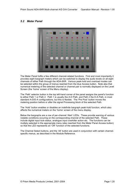
5.2 Meter Panel<br />
The Meter Panel fulfils a few different <strong>channel</strong>-related functions. First and most importantly it<br />
provides eight bargraph meters which can be switched to display the audio levels on all eight<br />
<strong>channel</strong>s of either Path through the <strong>ADA</strong>-<strong>8XR</strong>. Various peak-hold and overload modes can<br />
be selected within the group of menus reached from the blue Access button. Note also that<br />
numerical metering of the selected <strong>channel</strong> or <strong>channel</strong> pair is normally displayed on the Level<br />
Screen (the ‘home’ screen of the Menu display).<br />
The ‘Path’ selector button in the top left-hand corner of the panel assigns the panel’s function<br />
to either Path 1 or Path 2. Path 1 is usually the A-D Path, and Path 2 the D-A Path, in most<br />
standard A-D/D-A configurations, but this is flexible. The ‘Pre Post’ button moves the<br />
metering position before or after the signal Processing block of the selected Path.<br />
The ‘Hold’ button enables or disables an indefinite bargraph peak-hold function, which also<br />
affects the numerical meters on the ‘home’ screen of the menu display.<br />
Below the bargraphs are a row of per-<strong>channel</strong> ‘Alert’ LEDs. These provide warning of various<br />
notable conditions occuring on the corresponding <strong>channel</strong> of the selected Path. These<br />
include digital input lock-status, analogue input overkiller action etc. The functions can be<br />
multiply selected in the appropriate menu (also reached from the Meter Panel Access button)<br />
so that the LED represents an ‘OR’ function of the selected functions.<br />
The Channel Select buttons, and the ‘All’ button are used in conjunction with certain <strong>channel</strong>specific<br />
menus, as described in the Module Reference.<br />
© Prism Media Products Limited, 2001-2004 Page 1.20