ADA-8XR Multi-channel A/D D/A Converter Operation Manual
ADA-8XR Multi-channel A/D D/A Converter Operation Manual
ADA-8XR Multi-channel A/D D/A Converter Operation Manual

Create successful ePaper yourself
Turn your PDF publications into a flip-book with our unique Google optimized e-Paper software.
Prism Sound <strong>ADA</strong>-<strong>8XR</strong> <strong>Multi</strong>-<strong>channel</strong> A/D D/A <strong>Converter</strong> <strong>Operation</strong> <strong>Manual</strong> - Revision 1.00<br />
6 Adjustments and Upgrades<br />
The <strong>ADA</strong>-<strong>8XR</strong> mainframe has no need for any physical calibrations or jumpers; such<br />
calibrations as are necessary are managed in software. This is generally also true of the I/O<br />
Modules, but any user-adjustments that might apply are detailed in the Module Reference.<br />
6.1 Changing the mains voltage or fuse<br />
The mains (line) fuse and the mains voltage selector are carried within the IEC inlet on the<br />
rear of the <strong>ADA</strong>-<strong>8XR</strong>. The required fuse is a 2AT 20x5mm type. The voltage selector has<br />
two positions: ‘115V’ covers the range 90VAC to 130VAC, and ‘230V’ covers the range<br />
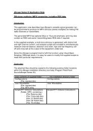
180VAC to 260VAC. The diagram below shows how to replace the fuse or change the<br />
voltage selection.<br />
Lever up the voltage selector / fuse holder cover<br />
by inserting a small, flat-bladed screwdriver into<br />
the slot as shown. Remove the red plastic holder.<br />
If replacing the fuse, use a 2AT 20mmx5mm type<br />
and, having placed it in the same location as the<br />
old fuse, replace the red plastic holder in the same<br />
orientation as before (with the selected voltage<br />
AWAY from the switch) and close the cover.<br />
To change the mains voltage selection, orient the red plastic holder with the desired voltage<br />
uppermost as shown in the diagram below. It is necessary to swap the positions of the fuse<br />
and a small metal clip on the opposite side of the holder. The correct side and location for<br />
each is shown in the diagram. Replace the red plastic holder in the new orientation (with the<br />
selected voltage AWAY from the switch) and close the cover. Check that the desired voltage<br />
is visible through the window. Note that unless the holder is inserted in the right orientation to<br />
match the positioning of the fuse and clip, the cover cannot be fully closed.<br />
© Prism Media Products Limited, 2001-2004 Page 1.23