AIR PERMEABILITY OF POROUS ASPHALT PAVEMENT
AIR PERMEABILITY OF POROUS ASPHALT PAVEMENT
AIR PERMEABILITY OF POROUS ASPHALT PAVEMENT

Create successful ePaper yourself
Turn your PDF publications into a flip-book with our unique Google optimized e-Paper software.
<strong>AIR</strong> <strong>PERMEABILITY</strong> <strong>OF</strong><br />
<strong>POROUS</strong> <strong>ASPHALT</strong> <strong>PAVEMENT</strong><br />
Giuliani F.<br />
Associate Professor – University of Parma – felice.giuliani@unipr.it<br />
Costa A.<br />
Associate Researcher – University of Parma – arianna.costa@unipr.it<br />
ABSTRACT<br />
We propose the results of experimental analyses on the draining capability of asphalt<br />
pavement by quantifying the filtration process indicator and permeability coefficient,<br />
through the use of an original air permeameter. This apparatus exploits the physical<br />
properties of air, and can solve the problems of measuring methods using water, which<br />
often yield contradictory results and non-repeatable tests. Such device is specifically<br />
conceived for pavement applications and ensures both a simple, rapid testing system,<br />
and high reliability and repeatability of the measurement.<br />
Keywords: porous asphalt, permeability, hydraulic conductivity.
4 th INTERNATIONAL SIIV CONGRESS – PALERMO (ITALY), 12-14 SEPTEMBER 2007<br />
1. BACKGROUND<br />
1.1 Introduction<br />
Rapid elimination of rainwater from road surfaces is a fundamental safety condition<br />
for vehicle traction, in particular during the braking phase. Asphalt pavements in porous<br />
mixture are studied to improve adhesion between tire and asphalt layer, by changing the<br />
superficial flow of water into filtration through a porous material.<br />
The high efficacy of porous asphalt layers in the road pavement, even in the most<br />
adverse weather conditions, calls for measurement devices of the drainage properties by<br />
measuring hydraulic conductivity.<br />
The actual conditions of water flow through a porous layer have been studied for<br />
several years and different measurement devices have been developed. Instruments are<br />
based on different hydraulic assumptions in the search for a simple valid method to<br />
quantify the permeability of porous asphalt in both the field and a laboratory setting.<br />
The instruments used in the field mostly consist in conventional apparatus for rapid<br />
assessment of permeability, which may be easy to use but provide parameters that are<br />
not really repeatable and not linkable to basic magnitude. Such methods generally refer<br />
to Darcy’s law [Bear, J., 1972], though in some cases the basic hypotheses are not met.<br />
1.2 Permeability measurement of porous asphalt layer with water<br />
permeameters<br />
The experiences documented in the area of hydraulic conductivity measurements in<br />
road surfaces which use water as reference fluid can be referred to two different<br />
typologies of instruments (permeameters), based on falling head devices and constant<br />
head devices.<br />
The former typology of permeameters is mostly used for hot mix asphalt having<br />
limited permeability. The latter typology is mostly used for open-graded hot mix asphalt<br />
with 15 % void content.<br />
Both typologies allow to calculate the permeability coefficient, in the former case on<br />
the basis of the time required for the filtration of a given water head, in the latter case on<br />
the basis of Darcy’s law of fluid filtration through a porous field. This law is based on<br />
particular theoretical assumptions which are difficult to be met in field tests.<br />
Darcy assumed that the flow occurs through a homogenous saturated material, the<br />
fluid is incompressible, and the flow is laminar, one-dimensional and under steady state<br />
conditions.<br />
Frequently used in Italy because provided for in many tenders, is the water<br />
permeameter at 250 mm falling head test on an area of 154 cm 2 , suited to quantifying<br />
the average drainage capability in dm 3 /min, according to a specific procedure devised<br />
by the Società Autostrade [Capitolato Speciale d’Appalto Società Autostrade, 2004].<br />
However, it is a conventional parameter that cannot be related to the permeability<br />
coefficient. A similar observation can be made about the Belgian Permeameter<br />
[Ministère des travaux publics, 1986]. These local procedures and equipements can be<br />
traced back to European Regulation [CEN EN 12697-40 (2005)].<br />
2
F. Giuliani – A. Costa<br />
There exist other systems [Cooley, A. 1999] which allow to determine permeability<br />
coefficient k in falling head conditions, but they apply to laboratory configurations and<br />
presuppone one-dimensional flow.<br />
In these conditions the following relation applies:<br />
a ⋅ L ⎛ h ⎞<br />
⋅<br />
⎜<br />
1<br />
k = ln<br />
⎟<br />
(1)<br />
A ⋅ t ⎝ h 2 ⎠<br />
where:<br />
k = coefficient of permeability (cm/s)<br />
a = area of stand pipe (cm 2 )<br />
L = width of sample (cm)<br />
A = cross area of permeameter (cm 2 )<br />
t = time over which head is allowed to fall (s)<br />
h 1 = water head at start of test (cm)<br />
h 2 = water head at end of test (cm)<br />
Recent experiments conducted by the authors [Giuliani, F. et al., 2006] have<br />
highlighted some theoretical problems typical of water permeability measurements on<br />
porous asphalt pavement in reaching the exact quantification of the permeability<br />
coefficient. In particular the assessment of the anisotropic condition of the drainage<br />
layer and the saturated conditions of such layer have appeared to be essential.<br />
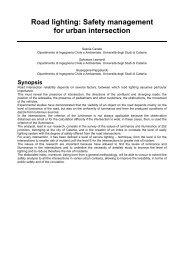
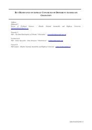
One-dimensional water permeability tests on specimens cored from slabs of porous<br />
asphalt concrete compacted in the laboratory along the compaction direction<br />
(orthogonal to the slab) and along the horizontal flow direction (coplanar to the slab),<br />
have allowed to determine the horizontal (kx) and vertical (kz) permeability coefficient<br />
(Figure 1).<br />
Q(z)<br />
Q(x)<br />
z<br />
x<br />
Figure 1 - One-directional filtration tests on porous asphalt concrete slabs<br />
3
4 th INTERNATIONAL SIIV CONGRESS – PALERMO (ITALY), 12-14 SEPTEMBER 2007<br />
The tests were carried out in saturated conditions and in a configuration coherent<br />
with the hypotheses of Darcy’s filtration law, and have highlighted significant<br />
anisotropy of porous asphalt slabs. A bidimensional study of flow through porous<br />
materials is therefore necessary.<br />
In particular, in different compacting and grading distribution conditions, the<br />
permeability coefficient value defined in the horizontal surface (kx) was almost double<br />
the value calculated along the vertical direction (kz).<br />
In order to correctly determine the permeability of porous asphalt layers it is of<br />
fundamental importance to verify the saturation conditions of the porous material, or, in<br />
a measurement carried out with water, it is essential that the flow starts in a material<br />
containing no air. In this case too, by means of a specific experimental apparatus, the<br />
constant head permeability tests, repeated on samples with different heights and through<br />
permeameters having different dimensions, have shown complete expulsion from the<br />
area within the porous asphalt mix after approx 30 min of continuous water flow<br />
[Giuliani, F. et al., 2006].<br />
Therefore, the solution suggested with the measurement system using the Belgian<br />
permeameter and the one of the Società Autostrade, for the preliminary soaking of the<br />
drainage surface before the test, appears to be inefficient.<br />
1.3 Permeability measurement of drainage surface by means of air<br />
permeameters<br />
The use of fluids different from water [Cabrera, J.G. et al., 1988] can significantly<br />
reduce the duration of the temporary transitional periods that are necessary to reach the<br />
saturation condition indispensable for measuring permeability with a good degree of<br />
repeatability. By considering air as the fluid used to analyze the filtration process, it is<br />
possible to overcome the problem of coexistence of two different phases within the<br />
voids of porous layers.<br />
The first permeameters to use air as measurement fluid for asphalt concrete<br />
permeability date back to the Eighties. Experiments conducted at that time led to the<br />
issue of the ASTM rule D 3637 – 84 (1991), which provides for two different test<br />
procedures: laboratory test and field test. The complicated set of tests and equipment<br />
necessary for the test prevented the diffusion of the method and its valid theoretical<br />
assumptions.<br />
This complicated measurement equipment can be simplified by using innovative<br />
instruments suitable to check flow and pressure in the filtration process both easily and<br />
precisely.<br />
In the following sections we will report on the calculation of air permeability<br />
according to Darcy’s law of one-directional filtration of fluids through a porous<br />
material. ASTM defines permeability K according to the following equation:<br />
Q μ L<br />
K =<br />
A ⋅ Δp<br />
⋅ Δt<br />
(2)<br />
4
F. Giuliani – A. Costa<br />
Where:<br />
K = permeability (cm 2 )<br />
Q = volume of air forced through the sample and corrected to 1 atm of (cm 3 )<br />
pressure<br />
L = thickness of sample (cm)<br />
A = area of sample (cm 2 )<br />
Δp = pressure in the cell as measured with the manometer (Pa)<br />
µ = viscosity of air (Pa·s)<br />
Δt = time required for water level to drop from one mark on the sight tube<br />
to another<br />
(s)<br />
Tests on the road or on porous asphalt slabs assume a three-dimensional flow. The<br />
symmetry of the set can allow to study the filtration process in a bidimensional space.<br />
Therefore equation (2) can be used by means of a suitable numerical modeling.<br />
2. <strong>AIR</strong> <strong>PERMEABILITY</strong> TEST BY MEANS <strong>OF</strong> A PROPER<br />
APPARATUS<br />
A permeability test was set under strict laboratory conditions. The test was carried<br />
out by means of an air permeameter, working on portions of porous road pavements<br />
having significant size (0.25 m 2 ). The slabs of porous asphalt concrete were<br />
manufactured employing the asphalt mixture taken from the finishing machine on the<br />
Italian site on the A15 highway, compacted by using a heavy roller compactor.<br />
The asphalt concrete, containing SBS hard modified bitumen in percentage of 4.15,<br />
showed a 17 % void content at the end of compaction.<br />
The slabs manufactured were 4 cm and 6 cm thick. The prismatic samples realized<br />
were set on a stiff base that constituted an impermeable separator able to reproduce the<br />
configuration characteristic of a porous pavement in the field.<br />
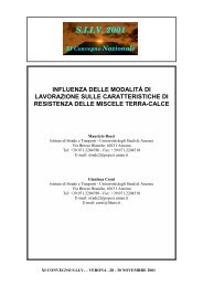
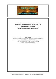
The tests were carried out using a permeameter formed by a vertical plexiglas<br />
cylinder stiffly joined to a horizontal base. The base was made of a plastic slab with a<br />
washer and had a weight as lock on it (Figure 2).<br />
The test equipment simulated the conditions present on road pavement, where a<br />
three-dimensional flow takes place, characterized by radial symmetry as to the<br />
barycentric vertical axis of the permeameter. Once the device was placed on the surface<br />
to be investigated, the test was carried out. The test consisted in the introduction of an<br />
air flow from the top of the cylinder and then the reading of the value of the pressure<br />
generated above the sample at the permeameter base. The reading was done by means<br />
of four radial plugs, connected to a pressure transducer. The air was introduced into the<br />
permeameter by means of a flexible pipe joined to a valve for the regulation of the flow.<br />
The valve was electrically operated and fed by compressed air.<br />
Data were acquired once a brief transitional periods was over, which lasted approx 2<br />
minutes. During this time the flow stabilized and the portion of material which the flow<br />
went through could be considered saturated.<br />
During this interval the system was calibrated, with the verification of the pressure<br />
in air inlet valves.<br />
5
4 th INTERNATIONAL SIIV CONGRESS – PALERMO (ITALY), 12-14 SEPTEMBER 2007<br />
The air flow delivered was constantly controlled electronically by means of a jet<br />
valve connected to a control unit for data acquisition. All the measurement phases were<br />
regulated and monitored through a personal computer.<br />
Flow<br />
gage<br />
Permeameter<br />
Base<br />
Sample<br />
Neoprene<br />
Lock<br />
Pressure<br />
gage<br />
Figure 2 - Setting procedure with air permeameter<br />
2.1 Choice of permeameter geometry<br />
The experimental device employed was the outcome of a preliminary search for<br />
measurement repeatability, validating the choice of each component of the instrument<br />
used with the aim of obtaining the best arrangement between scientific value of the<br />
results and test procedure practicality. Of the different components of the device, the<br />
choice of the size of permeameter diameter, related to the size of the aggregates in<br />
asphalt concrete, was one of the most significant phases.<br />
At the beginning the tests were carried out applying flow control, by manually<br />
operating the regulating jet valve placed before the inflow system.<br />
Each permeability test was repeated on three different points of the slab surface, first<br />
using the permeameter with 24 mm diameter, then the size was changed to 32 mm and<br />
48 mm. The aim was to find results that were not influenced by local conditions of the<br />
porous layer surface characterized by macro-roughness.<br />
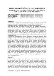
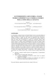
The graphs related to each permeameter were drawn on the basis of the<br />
measurements carried out, highlighting the trend of the pressure as a function of the<br />
flow present at the three test points (Figure 3).<br />
Analyzing the pressure-flow curve, it can be observed that, for the same air<br />
discharge introduced, the pressure decreases with the increase in the permeameter<br />
diameter. This is due, for the same discharge, to the larger area of the pavement surface<br />
pertaining to the permeameter, i.e. the area of the section which the fluid can flow<br />
through.<br />
The tests carried out through a smaller sized filtering surface highlighted very<br />
scattered curves; indeed, the greater the permeameter diameter compared to the<br />
6
F. Giuliani – A. Costa<br />
maximum size of aggregates employed, the more the recorded data are representative of<br />
the mixture and not affected by local heterogeneity which may be present.<br />
The curves obtained employing the 48 mm diameter permeameter yield a correct<br />
average of the permeability characteristics of the means studied and highlight the<br />
importance of the permeameter diameter used for the test.<br />
Based on these results, the experimental procedure was finally carried out<br />
employing a 100 mm diameter permeameter.<br />
1.6<br />
Permeameter φ 24 mm<br />
1.6<br />
Permeameter φ 32 mm<br />
1.2<br />
1.2<br />
Δp(mbar)<br />
0.8<br />
Δp(mbar)<br />
0.8<br />
0.4<br />
0.4<br />
0<br />
0<br />
0 0.2 0.4 0.6 0.8 1<br />
Q(l/s)<br />
0 0.2 0.4 0.6 0.8 1<br />
Q(l/s)<br />
0.6<br />
Permeameter φ 48<br />
0.4<br />
Δp(mbar)<br />
0.2<br />
0<br />
0 0.2 0.4 0.6 0.8 1<br />
Q(l/s)<br />
Figure 3 - Air permeability tests with different permeameter diameters<br />
7
4 th INTERNATIONAL SIIV CONGRESS – PALERMO (ITALY), 12-14 SEPTEMBER 2007<br />
In order to verify the system’s repeatability, nine tests were carried out on slabs<br />
41mm and 63 mm thick. Each time the permeameter was placed on different points of<br />
the porous surface (Figure 4).<br />
As can be seen by comparing the last graphs, the experimental curves obtained using<br />
the 48 mm diameter permeameter show lower variability in the results, due to the<br />
significant reduction in head loss.<br />
0.16<br />
Slab=41 mm; φ=100mm<br />
0.16<br />
Slab=63 mm; φ=100mm<br />
0.12<br />
0.12<br />
Δp(mbar)<br />
0.08<br />
Δp(mbar)<br />
0.08<br />
0.04<br />
0.04<br />
0<br />
0<br />
0 0.2 0.4 0.6 0.8 1<br />
Q(l/s)<br />
0 0.2 0.4 0.6 0.8 1<br />
Q(l/s)<br />
Figure 4 - Air permeability tests using 100 mm diameter permeameter<br />
The experimental curves show good fulfillment of Darcy’s Law hypotheses, indeed<br />
the trend of the Discharge-Pressure curves allows to identify a linear relationship<br />
between discharge and pressure up to discharge values of approx 0.17 l/s. Beyond this<br />
value the trend bilinear is expressed by the generic equation:<br />
P = aQ² + bQ (3)<br />
Once the test conditions were known, the conditions of laminar flow could be verified<br />
for discharge values lower than 0.17 l/s, calculating Reynolds’s Number of air:<br />
where:<br />
Re<br />
V<br />
⋅d<br />
air<br />
air<br />
= (4)<br />
ν<br />
air<br />
V air is the air speed, d is the diameter through which the flow takes place and ν air is the<br />
m 2<br />
Kinematic viscosity of air (10 -5<br />
s ).<br />
8
F. Giuliani – A. Costa<br />
Remembering that:<br />
Q<br />
air<br />
Vair = (5)<br />
A<br />
where:<br />
Q air is the maximum inlet air discharge (0.17 ·10 -3 m 3 s -1 ) and A is the area of<br />
permeameter section (7.85·10 -3 m 2 ), the final value is Re air<br />
= 22 . For such value of<br />
Reynolds’s Number the flow can be considered laminar [Bear, J. (1972)].<br />
The laboratory experimental analysis, aimed at the calibration of the test<br />
methodology and the acquisition of experimental data, is followed by a second phase in<br />
which the data obtained are processed by means of an analysis based on a finite element<br />
model for the reconstruction of the flow model that is able to overcome the limit of a<br />
one-dimensional calculation approach.<br />
3. CALCULATION <strong>OF</strong> <strong>AIR</strong> <strong>PERMEABILITY</strong> COEFFICIENT<br />
BY MEANS <strong>OF</strong> FEM ANALYSIS<br />
The test set requires a three-dimensional flow within the surface drainage layer of<br />
asphalt pavement.<br />
The radial symmetry of the test set up allows to study the problem in two<br />
dimensions only, schematizing the porous medium to small portions by a mesh of finite,<br />
triangular elements whose vertices are at a distance of 2 ÷ 2.5 mm (Figure 5).<br />
The permeability coefficient of the porous asphalt mix is calculated by solving the<br />
physical problem by means of a finite element method with the program SEEP 2D,<br />
which is valid in the hypothesis of laminar flow.<br />
The boundary conditions were subsequently fixed: free flow along the surface of the<br />
outside border at the base of the permeameter and a known value of pressure within the<br />
filtration area. Once the entering air discharge and the relative pressure value are fixed,<br />
both during the experimental stage, and the isotropy of the material is assumed, through<br />
a back-calculation process it was possible to determine the permeability coefficient of<br />
the porous medium.<br />
Below are the k-Q curves obtained by representing the results of the modeling<br />
related to the experimental tests that were accomplished with permeameter Φ 100 mm<br />
on porous slabs of different thickness (Figure 6).<br />
Analyzing the curves it can be observed that the slabs having 40 mm thickness show<br />
greater flow capability than the thicker sample (approx 60 mm), consistently with the<br />
physical phenomenon.<br />
Both types of slabs, for discharge approx 0.17 l/min, show constant values of air<br />
permeability and these values are similar among themselves, thus confirming the<br />
hypothesis of laminar flow and the validity of Darcy’s law.<br />
9
4 th INTERNATIONAL SIIV CONGRESS – PALERMO (ITALY), 12-14 SEPTEMBER 2007<br />
Figure 5 - 2D Modeling of air permeability test<br />
0.01<br />
0.009<br />
k [m/s]<br />
0.008<br />
0.007<br />
0.006<br />
0.005<br />
0.004<br />
Slab 63 mm<br />
0.003<br />
Slab 41 mm<br />
0.002<br />
0.001<br />
0<br />
0.00 0.05 0.10 0.15 0.20<br />
Q [l/s]<br />
10
F. Giuliani – A. Costa<br />
Figure 6 - Air Permeability k versus discharge for slabs of porous concrete<br />
having 41 mm and 63 mm thickness<br />
3.1 Conversion of permeability values.<br />
Having calculated the coefficient of air permeability Ki air it was possible to express the<br />
relationship between this coefficient and the coefficient of water permeability K water for<br />
the same porous medium in the same boundary conditions:<br />
leading to:<br />
K<br />
K<br />
air<br />
water<br />
γ<br />
air<br />
⋅ d<br />
=<br />
μ<br />
K<br />
air<br />
4. CONCLUSIONS<br />
2<br />
μ<br />
⋅<br />
γ<br />
water<br />
water<br />
water<br />
K air<br />
⋅ d<br />
2<br />
ν<br />
=<br />
ν<br />
water<br />
air<br />
10 −6<br />
1<br />
= 10<br />
−<br />
−5<br />
=<br />
10<br />
= 10 ⋅<br />
(7)<br />
The employment of air as fluid to be used in the study of the permeability of porous<br />
media, and in particular of porous asphalt mixtures, is undoubtedly a good choice,<br />
which by itself allows to overcome many practical and theoretical problems linked to<br />
the use of water.<br />
The adoption of air systems limits the problems connected to the coexistence of<br />
phases in porous surfaces, and allows to quickly reach the saturation conditions of the<br />
porous means required by Darcy’s hypotheses.<br />
The use of air for in situ permeability measurements allows to remove the<br />
difficulties met in field due to the water supply on the road, and consequently adopt<br />
theoretical schemes for the filtration in constant head conditions.<br />
The air permeability test devised in this research did not appear to be independent of<br />
the permeameter diameter. The same thing can not be affirmed about the effect of<br />
thickness of the layers on the value of permeability. Indeed it is necessary to increase<br />
the study on a larger numbers of specimens with different thickness and to increase<br />
more the precision of measurement.<br />
Darcy’s Law, often applied without the necessary attention in road applications, is<br />
significant only when the entire fundamental hypotheses are verified or correctly<br />
approximated.<br />
The results obtained from the experimental investigation and the subsequent<br />
numerical modeling allow to draw the following conclusions:<br />
- The permeameter section must guarantee the supply in situ of a fixed discharge and,<br />
at the same time, must not trigger undesirable size effects. Such effects are less<br />
relevant when the ratio between the permeameter diameter and the sample size<br />
increases, in both the size of plane and thickness. The suggested size of 100 mm for<br />
the permeameter diameter (more than five times the maximum nominal size of the<br />
stone aggregate in the mixture) has proved to be the best in describing the filtration<br />
process.<br />
(6)<br />
11
4 th INTERNATIONAL SIIV CONGRESS – PALERMO (ITALY), 12-14 SEPTEMBER 2007<br />
- For the original and rigorous fitting studied and for discharge values lower than 0.17<br />
l/s, Darcy’s Law hypotheses may be considered effective. This allows to determine<br />
the permeability coefficient of the slabs of porous asphalt mixture studied.<br />
- The steady state flow established and the linearity of the relationship between<br />
pressure and air flow discharge of laminar type, allow to convert, when necessary,<br />
the value of coefficient of air permeability into the coefficient of water permeability.<br />
REFERENCES<br />
BEAR, J. (1972) – “Dynamics of fluids in porous media”, Inc. New York, Dover<br />
Publications, USA.<br />
CABRERA, J. G., LYNSDALE, C. J. (1988) – “A new gas permeameter for measuring<br />
the permeability of mortar and concrete”, Magazine of concrete research. Vol. 40 N.<br />
144.<br />
Capitolato Speciale d’Appalto Società Autostrade, (2004).<br />
COOLEY, A. (1999) – “Permeability of superpave mixtures: evaluation of field<br />
permeameters” – National Center for Asphalt Technology, Report No. 99-1, Auburn<br />
University, Alabama, USA.<br />
CEN EN 12697-40 (2005) – “Bituminous mixtures – Test methods for hot mix asphalt”<br />
– Part 40 : In situ drainability, Brussels, Belgique.<br />
CEN EN 13108-7 (2003) – “Bituminous mixtures – Materials specifications” - Draft<br />
Porous Asphalt, Brussels, Belgique.<br />
GIULIANI, F., COSTA, A. (2006) – “Experimental evaluation of permeability of<br />
porous asphalt pavement in constant head condition” – Department of Civil<br />
Engineering, University of Parma, Italy<br />
KANITPONG, K., BENSON, C., BAHIA, H. (2001) – “Hydraulic conductivity<br />
(permeability) of laboratory compacted asphalt mixtures” – Transportation Research<br />
Board 80th Annual Meeting Paper No. 01-2997, Washington, USA.<br />
MALLICK, R., COOLEY, A., TETO, M., BRADBURY, R., PEABODY D. (2001) –<br />
“An evaluation of factors affecting permeability of superpave designed pavements” –<br />
Transportation Research Board 80th Annual Meeting Paper No. 01-2763, Washington,<br />
USA.<br />
Ministère des Travaux Publics (1986) – “Enrobés drainants” – Administration des<br />
Routes Circulaire n° A-169-86/04000, Bruxelles, Belgique.<br />
NCHRP (2004) – “Characteristics for use with performance related specifications for<br />
hot mix asphalt” – National Cooperative Highway Research Program, Research Result<br />
Digest 291, USA.<br />
12