Footprint Attenuation with 5D Interpolation - Arcis
Footprint Attenuation with 5D Interpolation - Arcis
Footprint Attenuation with 5D Interpolation - Arcis

Create successful ePaper yourself
Turn your PDF publications into a flip-book with our unique Google optimized e-Paper software.
<strong>Footprint</strong> <strong>Attenuation</strong> <strong>with</strong> <strong>5D</strong> <strong>Interpolation</strong><br />
Peter Cary and Mike Perz<br />
<strong>Arcis</strong> Seismic Solutions, Calgary, Alberta, Canada<br />
In recent years, <strong>5D</strong> interpolation has become a very popular<br />
method for regularizing seismic data before 3D prestack<br />
migration. In addition to its main purpose of reducing the<br />
generation of migration artifacts due to irregular spatial<br />
sampling, <strong>5D</strong> interpolation also has the very beneficial sideeffect<br />
of attenuating acquisition footprint during the interpolation<br />
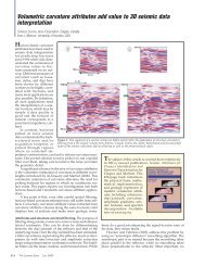
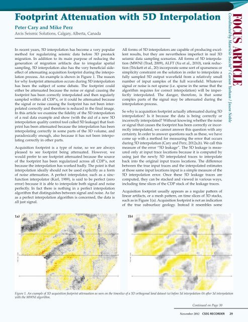
process. An example is shown in Figure 1. The reason<br />
for why footprint attenuation occurs during <strong>5D</strong> interpolation<br />
has been the subject of some debate. The footprint could<br />
either be attenuated because the noise or signal causing the<br />
footprint has been correctly interpolated and then regularly<br />
sampled <strong>with</strong>in all CDP’s, or it could be attenuated because<br />
the signal or noise causing the footprint has not been interpolated<br />
correctly and therefore is reduced in the final image.<br />
In this article we examine the fidelity of the <strong>5D</strong> interpolation<br />
of a real data example and show (<strong>with</strong> the aid of a new <strong>5D</strong><br />
interpolation quality control tool called <strong>5D</strong> leakage) that footprint<br />
has been attenuated because the interpolation has been<br />
interpolating correctly in some parts of the 3D volume, and<br />
paradoxically enough, also because it has not been interpolating<br />
correctly in other parts.<br />
Acquisition footprint is a type of noise, so we are always<br />
pleased to see footprint being attenuated. However, we<br />
would prefer to see footprint attenuated because the source<br />
of the footprint has been regularized across all CDP’s, not<br />
because the interpolation has worked badly. The point is that<br />
interpolation ideally should not be used explicitly as a form<br />
of noise attenuation. A perfect interpolator, such as a sincfunction<br />
interpolator (Karl, 1989), is said to be perfect (zero<br />
error) because it is able to interpolate both signal and noise<br />
perfectly. In fact there is nothing in a perfect interpolation<br />
algorithm that distinguishes between signal and noise. As far<br />
as a perfect interpolation algorithm is concerned, the data is<br />
all just signal.<br />
All forms of <strong>5D</strong> interpolators are capable of producing excellent<br />
results, but they are nevertheless imperfect in real 3D<br />
seismic data sampling scenarios. All forms of <strong>5D</strong> interpolation<br />
(MWNI (Trad, 2009), ALFT (Xu et al., 2010), rank reduction<br />
(Trickett et al., 20) incorporate some sort of sparseness or<br />
simplicity constraint on the solution in order to interpolate a<br />
fully sampled <strong>5D</strong> output wavefield from a relatively small<br />
number of input samples of the full wavefield. Whatever<br />
signal or noise is not sparse (i.e. sparse in the sense that the<br />
algorithm requires for correct interpolation) will be imperfectly<br />
interpolated. The danger, therefore, is that some<br />
complex parts of the signal may be attenuated during the<br />
interpolation process.<br />
So why is acquisition footprint actually attenuated during <strong>5D</strong><br />
interpolation Is it because the data is being correctly or<br />
incorrectly interpolated Without knowing whether the noise<br />
or signal that causes the footprint has been correctly or incorrectly<br />
interpolated, we cannot answer this question <strong>with</strong> any<br />
certainty. In order to answer questions such as these, we have<br />
come up <strong>with</strong> a method for measuring the error that occurs<br />
during <strong>5D</strong> interpolation (Cary and Perz, 2012a,b). We call this<br />
measure of the error “<strong>5D</strong> leakage”. The <strong>5D</strong> leakage is measured<br />
only at input trace locations because it is computed by<br />
using just the newly <strong>5D</strong> interpolated traces to interpolate<br />
back into the original input traces locations. The difference<br />
between the true input traces and the interpolated estimates<br />
at those same input locations input is a simple measure of the<br />
<strong>5D</strong> interpolation error. Once these <strong>5D</strong> leakage traces are<br />
computed, they can be stacked and viewed in various ways,<br />
including time slices of the CDP stack of the leakage traces.<br />
Acquisition footprint usually appears as a regular pattern of<br />
linear artifacts, or a mesh pattern, on time slices of 3D stacks,<br />
such as in Figure 1(a). Acquisition footprint is not an indication<br />
of the true subsurface geology. Instead it resembles some<br />
FOCUS ARTICLE<br />
Coordinated by Mauricio Sacchi* / Carson Yarham / Jason Noble<br />
1a) 1b)<br />
Figure 1. An example of 3D acquisition footprint attenuation as seen on the timeslice of a 3D orthogonal land dataset (a) before 5d interpolation (b) after 5d interpolation<br />
<strong>with</strong> the MWNI algorithm.<br />
Continued on Page 30<br />
November 2012 CSEG RECORDER 29
Focus Article Cont’d<br />
<strong>Footprint</strong> <strong>Attenuation</strong> <strong>with</strong> <strong>5D</strong> <strong>Interpolation</strong><br />
Continued from Page 29<br />
aspect of the acquisition geometry, such as the shot or receiver<br />
layout. The many causes of acquisition footprint have been investigated<br />
extensively (e.g. Hill et al., 1999). A likely reason for the<br />
strong footprint that appears in the shallow parts of many 3D<br />
images is the fact that the particular offsets and azimuths that are<br />
most contaminated <strong>with</strong> source-generated or backscattered noise<br />
at early times are sampled only <strong>with</strong>in every n-th CDP in the inline<br />
or crossline directions, where n is the number of CDP’s between<br />
source or receiver lines. As a result, a regular pattern of noise<br />
appears at every n-th inline or crossline.<br />
Various aspects of reflected signal, such as residual normal<br />
moveout, can also cause acquisition footprint. For example, a<br />
multiple reflection, or a primary reflection that is not flat across<br />
all offsets due to an NMO velocity error may generate a regular<br />
footprint pattern due to the regular wavelet sampling at particular<br />
offsets <strong>with</strong>in a pattern of CDP’s. Even amplitude variations<br />
<strong>with</strong> offset (AVO) on a perfectly flat reflector will generate some<br />
degree of amplitude footprint on the final stacked image due to<br />
the pattern of offset sampling <strong>with</strong>in the CDP grid.<br />
After <strong>5D</strong> interpolation, the offset and azimuth sampling of traces<br />
<strong>with</strong>in neighboring CDP’s is regularized. Regardless of whether<br />
it was some aspect of signal or noise that was the original cause<br />
of the footprint, the fact that the signal and noise are sampled<br />
identically at all offsets and azimuths <strong>with</strong>in every CDP after <strong>5D</strong><br />
interpolation will make the regular footprint pattern disappear.<br />
At least that is the argument, if you believe that <strong>5D</strong> interpolation<br />
is interpolating the full wavefield (i.e. signal plus noise) perfectly.<br />
The trouble is that, even though the <strong>5D</strong> interpolated data may<br />
look excellent, we have already established that <strong>5D</strong> interpolation<br />
is not perfect, so there is at least some possibility that footprint is<br />
being attenuated because the aspect of the noise or signal that<br />
caused the footprint has not been correctly interpolated. To<br />
generate footprint, you require two things: (1) a variation of the<br />
wavefield <strong>with</strong> offset (and/or azimuth), and (2) a somewhat<br />
regular, but sparse, sampling of offsets and azimuths <strong>with</strong>in<br />
CDPs. To attenuate the footprint <strong>with</strong> an interpolation method,<br />
you need to do one (or both) of two things: either remove<br />
requirement (1) <strong>with</strong> an imperfect interpolation, or remove<br />
requirement (2) <strong>with</strong> a good interpolation/regularization<br />
method. How is one to know which of these two situations is<br />
causing the footprint attenuation in any particular case<br />
An examination of the accuracy of the interpolation, as measured<br />
by the <strong>5D</strong> leakage, can answer this question. If the aspect of the<br />
wavefield that is causing the footprint is being correctly interpolated,<br />
then the stack of the <strong>5D</strong> leakage traces will not contain any<br />
sign of the footprint. This would be the case if the source-generated<br />
noise, or the multiple, or whatever signal or noise was the<br />
origin of the footprint in the first place was being correctly interpolated<br />
into all new trace positions. The source of the footprint<br />
would then also disappear from the <strong>5D</strong> leakage. On the other<br />
hand, if the footprint does appear in the <strong>5D</strong> leakage, then we<br />
know that the aspect of the signal or noise that was the origin of<br />
footprint was not being interpolated correctly. <strong>Footprint</strong> in the<br />
<strong>5D</strong> leakage implies a poor interpolation. Absence of footprint in<br />
the <strong>5D</strong> leakage implies a good interpolation.<br />
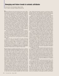
Figure 2 is taken from the shallow section (300ms) of the 3D<br />
volume from an orthogonal land 3D dataset. The original stack<br />
2a)<br />
2b)<br />
2c)<br />
Figure 2. An example of footprint attenuation at the shallow time level (300ms)<br />
of a 3D dataset (a) before 5d interpolation (b) after 5d interpolation, and (c) the<br />
5d leakage (a measure of the error in the interpolation). The fact that the 5d<br />
leakage contains much of the footprint that has been removed between (a) and (b)<br />
implies that the aspect of the wavefield that is causing the footprint (probably<br />
some type of noise) has been interpolated imperfectly at this time level.<br />
Continued on Page 32<br />
30 CSEG RECORDER November 2012
Focus Article Cont’d<br />
<strong>Footprint</strong> <strong>Attenuation</strong> <strong>with</strong> <strong>5D</strong> <strong>Interpolation</strong><br />
Continued from Page 30<br />
shows a fairly large amount of footprint which is probably<br />
caused by some remnant of source-generated noise that has not<br />
been completed removed during processing. The attenuation of<br />
the footprint by <strong>5D</strong> interpolation is both dramatic and beneficial<br />
to the final image. The time slice of the <strong>5D</strong> leakage stack shows a<br />
large amount of footprint, which indicates that the noise has not<br />
been perfectly interpolated.<br />
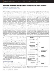
Figure 3 is taken from a deeper section (1500ms) of the same 3D<br />
volume as in Figure 2. The footprint in this case is less strong<br />
than in Figure 2, and its true cause (whether due to signal or<br />
noise) is not obvious from examining the data but it is likely due<br />
3a)<br />
to some variation <strong>with</strong> offset in the moveout or amplitude on a<br />
primary or multiple reflection. The footprint attenuation by <strong>5D</strong><br />
attenuation is more subtle in this case than in Figure 2, but the<br />
attenuation is no less important at this time level because of the<br />
similarity of some of the real geologic features to the linear footprint.<br />
At this time level, the time slice of the <strong>5D</strong> leakage shows<br />
only slight hints of footprint, so in this case, whatever signal or<br />
noise was the original cause of the footprint is being very well<br />
interpolated.<br />
The examination of the <strong>5D</strong> leakage in Figures 2 and 3 has enabled<br />
us to know what is really happening when footprint is attenuated<br />
by <strong>5D</strong> interpolation. The answer in the case of this 3D<br />
volume is that footprint attenuation is occurring for two different<br />
reasons. In the shallow section, footprint was attenuated as a<br />
result of imperfect interpolation, and in the deeper section, footprint<br />
was attenuated as a result of a good interpolation.<br />
These findings should not surprise us if we reflect on the data<br />
requirements for a good <strong>5D</strong> interpolation. The smooth spatial variations<br />
of moveout and AVO on primary and multiple reflections<br />
can be described by relatively simple wavenumber spectra, and<br />
such simple variations in the data are well reconstructed by <strong>5D</strong><br />
interpolation given its sparseness assumption. By contrast, the<br />
rapid offset variations of steeply-dipping source-generated noise<br />
are less well-suited to the assumptions of <strong>5D</strong> interpolation so we<br />
should not be surprised that this type of noise is not being perfectly<br />
reconstructed. Since this 3D dataset is typical of most land orthogonal<br />
3D datasets in terms of its signal and noise sampling issues,<br />
we would expect to see that footprint is attenuated by <strong>5D</strong> attenuation<br />
in many other 3D datasets for both of these reasons.<br />
In summary, this article has examined the issues surrounding the<br />
question of why <strong>5D</strong> interpolation attenuates 3D acquisition footprint.<br />
We have found that attenuation occurs because 1) signal<br />
in the deeper section has been interpolated and then sampled<br />
3b)<br />
3c)<br />
Figure 3. An example of footprint attenuation at a deeper time level (1500ms) of a 3D dataset (a) before 5d interpolation (b) after 5d interpolation, and (c) the 5d leakage.<br />
The fact that the 5d leakage contains very little footprint implies that the aspect of the wavefield that is causing the footprint (probably some aspect of the signal) has been<br />
interpolated correctly at this time level.<br />
32 CSEG RECORDER November 2012<br />
Continued on Page 33
<strong>Footprint</strong> <strong>Attenuation</strong> <strong>with</strong> <strong>5D</strong> <strong>Interpolation</strong><br />
Continued from Page 32<br />
regularly in the output CDP’s and<br />
2) noise in the shallow section has<br />
not been properly interpolated so<br />
its effect has been reduced in the<br />
final image. We have come to<br />
these conclusions based on the<br />
recently devised method of measuring<br />
<strong>5D</strong> leakage (Cary and Perz,<br />
2012a,b). <strong>5D</strong> leakage has proven<br />
to be very useful not only for<br />
enquiring into this footprint<br />
attenuation issue, but also for<br />
enquiring into other important<br />
issues such as the preservation of<br />
resolution. R<br />
References<br />
Cary, P. and M. Perz, 2012a, “High Resolution<br />
<strong>5D</strong> <strong>Interpolation</strong>: Measuring and<br />
Compensating for <strong>5D</strong> Leakage”, CSEG<br />
Conference Abstracts.<br />
Cary, P. and M. Perz, 2012b, “<strong>5D</strong> leakage:<br />
measuring what <strong>5D</strong> interpolation misses”,<br />
82nd Annual International Meeting, SEG,<br />
Expanded Abstracts.<br />
Hill, S., M. Shultz and J. Brewer, 1999,<br />
“Acquisition footprint and fold-of-stack plots”,<br />
The Leading Edge, 18, 686-695.<br />
Karl, J. H., 1989, An Introduction to Digital<br />
Signal Processing, Academic Press, 341pp.<br />
Trad, D., 2009, Five-dimensional interpolation:<br />
Recovering from acquisition constraints:<br />
Geophysics, 74,, no. 6, V123-V132.<br />
Trickett, S., L. Burroughs, A. Milton, L.<br />
Walton, and R. Dack, 2010, Rank-reductionbased<br />
trace interpolation: 81st Annual<br />
International Meeting, SEG, Expanded<br />
Abstracts, 1989-1992.<br />
Xu, S., Z. Yu, and G. Lambare, 2010,<br />
“Antileakage Fourier transform for seismic data<br />
regularization in higher dimensions”, 75, no. 6,<br />
WB113-WB120.<br />
Focus Article Cont’d<br />
Peter Cary has B.Sc. and M.Sc. degrees in physics, and a B.A.degree in<br />
philosophy from the University of Toronto, and a Ph.D. in geophysics (1987)<br />
from Cambridge University, England. He worked for Chevron both in<br />
Calgary and in La Habra, California from 1982 to 1984 and was Manager of<br />
Geophysical Research <strong>with</strong> Pulsonic Geophysical Ltd. from 1988 to 1996 and<br />
Chief Geophysicist <strong>with</strong> Sensor Geophysical Ltd. 1996 to 2011. He is<br />
presently Chief Geophysicist, Processing <strong>with</strong> <strong>Arcis</strong> Seismic Solutions. He<br />
has presented and published many papers on seismic processing, and<br />
served as technical program chairman of the SEG 2000 Annual Meeting and<br />
of the 1993 CSEG Annual Meeting. He served as CSEG president in 2004-05<br />
and was 2nd V.P. of the CSEG in 1996-97. He was an associate editor (seismic<br />
processing) of Geophysics from 1998-2001. One of his specialities is<br />
processing and writing software for multicomponent seismic data.<br />
Mike Perz received his BSc in Physics from the University of Toronto in<br />
1990 and his MSc in Geophysics from the University of British Columbia<br />
in 1993. Shortly thereafter, he joined Pulsonic Geophysical where his main<br />
focus was writing prestack time migration software. Four years later he<br />
moved to Geo-X Systems Ltd, later part of Divestco Inc., where he spent<br />
thirteen years, first writing geophysical applications software then managing the R and D<br />
group. In 2010, Mike moved over to <strong>Arcis</strong> Corporation where he was employed as Vice<br />
President of Technology and Integration at the time the organization was purchased by<br />
TGS. His current title is Manager Technology, <strong>Arcis</strong> Processing and Reservoir Services, and<br />
his role is two-tiered, focusing on both geophysical software and business development. His<br />
research interests span all elements of land processing including data regularization,<br />
prestack migration, fracture detection, deconvolution, tomostatics and multiple attenuation.<br />
November 2012 CSEG RECORDER 33