Overhead Irrigation Guide - Senninger Irrigation
Overhead Irrigation Guide - Senninger Irrigation
Overhead Irrigation Guide - Senninger Irrigation

Create successful ePaper yourself
Turn your PDF publications into a flip-book with our unique Google optimized e-Paper software.
www.<br />
com<br />
<strong>Senninger</strong>.<br />
OVERHEAD<br />
IRRIgAtIOn<br />
SOLID SEt & nuRSERy/gREEnHOuSE<br />
Application guide for container stock
Rating Performance<br />
Average Application Rate<br />
Average application rate is the average depth of<br />
water applied over a given interval of time under an<br />
irrigation system. This is usually indicated as inches<br />
per hour (in/hr) or millimeters per hour (mm/hr).<br />
Coefficient of Uniformity (CU)<br />
Christiansen’s CU identifies the evenness of an<br />
irrigation system’s water distribution by comparing<br />
the average difference in the amount of water<br />
collected in each catch can to the mean amount of<br />
water collected by all catch cans.<br />
Scheduling Coefficient (SC)<br />
SC calculates the ratio of the driest area’s application<br />
rate divided into the average application rate. The<br />
result is always greater than or equal to one (a<br />
value of one would be perfect) and indicates the<br />
total amount of irrigation time required to bring the<br />
application rate in the driest area up to the average<br />
application rate. For example: if a system has an SC<br />
of 1.5 and an average application rate of 0.5 inch<br />
(12.7 mm) of water per one hour, it would take<br />
1.5 x one hour or 1.5 hours for the driest area to<br />
receive the average application depth of 0.5 inch<br />
(12.7 mm) of water.<br />
1<br />
irrigation System<br />
Pressure Regulation<br />
Variations in system pressure can result in erratic<br />
application rates. Optimum performance of a<br />
well-designed overhead container irrigation system<br />
can be achieved by using pressure regulators. The<br />
<strong>Senninger</strong> Pressure-Master Regulator® maintains a<br />
constant preset outlet pressure while handling inlet<br />
pressure up to 150 psi (10.35 bar).<br />
<strong>Senninger</strong> <strong>Irrigation</strong>’s<br />
WinSIPP2 software utilizes<br />
your specific criteria to<br />
optimize system design and<br />
installation.<br />
irrigation systems should be evaluated to<br />
establish uniformity of water application<br />
to identify run times that minimize<br />
dry areas. Uniformity is determined<br />
by developing a sprinkler’s specific<br />
application pattern on the ground by<br />
collecting and measuring water depth<br />
in catch cans at regular intervals out<br />
from the sprinkler. This “profile” is<br />
established and then overlapped based<br />
on lateral and sprinkler spacing in order<br />
to develop the Coefficient of Uniformity<br />
and water Scheduling Coefficient ratings<br />
as described below. These values are<br />
referred to in this guide as CU and SC<br />
respectively.<br />
www.<br />
com<br />
<strong>Senninger</strong>.<br />
®
www.<br />
com<br />
<strong>Senninger</strong>.<br />
®<br />
One important goal of a well-designed container<br />
irrigation system is to achieve the highest uniformity<br />
while considering spacing restrictions, operating<br />
pressure and application rate to best meet the<br />
needs of your crop.<br />
This guide includes examples of each of the<br />
<strong>Senninger</strong> products recommended for an <strong>Overhead</strong><br />
Container <strong>Irrigation</strong> System. The products shown<br />
in Chart A target an application rate of 0.5 inch<br />
(12.7 mm) per hour while considering the best<br />
*SQ = Square orifice nozzle for better stream break-up, improves uniformity.<br />
**WV = White Vane, stream straightening vane, maximizes throw.<br />
***RV = Red Vane, spiral vane for better stream break-up, improves uniformity.<br />
How To Design a System<br />
spacing, operating pressure and nozzle combination<br />
to achieve optimum uniformity.<br />
You can use this information to choose the<br />
product that best fits your situation. Refer to the<br />
corresponding page numbers for additional design<br />
information for the product selected. For additional<br />
options regarding specific applications not<br />
addressed in this chart please contact <strong>Senninger</strong><br />
<strong>Irrigation</strong>.<br />
ChARt A- Product Selection for <strong>Overhead</strong> Container<br />
Data based on a riser height of 18 inches (0.457 mm)<br />
OPERAtIng APPLICAtIOn<br />
PRODuCt Cu SC SquARE SPACIng PRESSuRE nOZZLE RAtE PAgE<br />
% Feet Meters (psi) (bar) # (in/h) (mm/h) #<br />
mini-Wobbler ® 92.4 1.17 20 x 20 6.10 x 6.10 20 1.38 8 0.47 11.94 3<br />
Xcel-Wobbler ® HA 86.7 1.30 25 x 25 7.62 x 7.62 25 1.72 10 0.54 13.72 5<br />
Smooth Drive 89.3 1.17 25 x 25 7.62 x 7.62 30 2.07 8 0.37 9.40 7<br />
Smooth Drive 89.3 1.35 30 x 30 9.14 x 9.14 30 2.07 8 0.26 6.60 7<br />
2023-1 Impact 96.0 1.19 25 x 25 7.62 x 7.62 45 3.10 8 SQ* 0.46 11.68 9<br />
2023-1 Impact 89.3 1.25 30 x 30 9.14 x 9.14 45 3.10 9 WV** 0.40 10.16 9<br />
3023-2 Impact 90.4 1.17 35 x 35 10.7 x 10.7 45 3.10 10 RV*** x 5 RV 0.48 12.19 9<br />
4023-2 Impact 91.2 1.16 40 x 40 12.2 x 12.2 45 3.10 12 WV x 6 RV 0.51 12.95 9<br />
5023-2 Impact 87.3 1.22 45 x 45 13.7 x 13.7 50 3.45 13 WV x 8 RV 0.51 12.95 9<br />
2
mini-Wobbler ®<br />
Advantages of a low pressure 15-20 psi or<br />
(1.03 - 1.38 bar) mini-Wobbler irrigation System<br />
3<br />
irrigating<br />
• Outstanding Uniformity<br />
• Large diameter of coverage at low pressures<br />
• Rain-like pattern for gentle application<br />
• Ideal for PVC or Poly Pipe systems<br />
tAble 2.<br />
Quantity of Units Based<br />
on System Flow Rate<br />
Flow Rate<br />
Determine Zone Flow<br />
table 2 will determine the number of<br />
mini-Wobblers based on system flow<br />
rate at 20 psi (1.38 bar).<br />
nozzle<br />
#6<br />
The unique off-center<br />
rotary action of the<br />
mini-Wobbler provides<br />
outstanding uniformity<br />
over a large diameter.<br />
Follow these 4 Steps to design a mini-Wobbler irrigation system...<br />
1Determine Application Rate & Maximum length of laterals<br />
Based on the selection of the mini-Wobbler from Chart A on page 2, use Table 1 to help determine<br />
the application rate and the maximum length of laterals using PVC (maximum allowable velocity of<br />
5 ft or 1.52 m per second as recommended by PVC manufacturers) or Poly Pipe for 3/4" or 1" sizes.<br />
tAble 1. mini-Wobbler<br />
Maximum Length of Lateral on 20 ft (6.1 m); Spacing at 20 psi (1.38 bar)<br />
3/4" PVC 1" PVC 3/4" POLy 1" POLy<br />
APPLICAtIOn (0.930 I.D.) (1.195 I.D.) (0.817 I.D.) (1.05 I.D.)<br />
nOZZLE RAtE Class 200 Class 160 Poly Poly<br />
# (in/h) (mm/h) (ft) (m) (ft) (m) (ft) (m) (ft) (m)<br />
6 0.26 6.60 180 54.9 300 91.4 140 42.7 220 73.2<br />
7 0.36 9.14 140 42.7 220 73.2 120 36.6 180 54.9<br />
8 0.47 11.9 120 36.6 200 61.0 100 30.5 160 48.8<br />
Data based on
3<br />
www.<br />
com<br />
<strong>Senninger</strong>.<br />
Determine Spacing<br />
Square Spacing<br />
Head Spacing: 20 ft (6.10 m)<br />
Row Spacing: 20 ft (6.10 m)<br />
Offset from sides: 5 ft (1.52 m)<br />
Offset from ends: 5 ft (1.52 m)<br />
Offset<br />
Head Spacing<br />
Side Offset<br />
Recommended spacings based<br />
on maximum uniformities from<br />
Chart A, page 2.<br />
®<br />
End<br />
Offset<br />
Head Spacing<br />
Row Spacing<br />
Single Row Spacing<br />
Head Spacing: 10 ft (3.05 m)<br />
Offset from sides: 7.5 ft (2.87 m)<br />
Offset from ends: 5 ft (1.52 m)<br />
irrigating mini-Wobbler ®<br />
tAble 3. mini-Wobbler- Additional Design Options at 20 psi (1.38 bar)<br />
(not shown on Chart A, page 2)<br />
RISER APPLICAtIOn<br />
nOZZLE SquARE SPACIng Cu SC HEIgHt RAtE<br />
# (ft) (m) (%) (in) (cm) (ft) (m)<br />
4 10 X 10 3.05 X 3.05 94.8 1.13 18 45 0.48 12.2<br />
5 10 X 10 3.05 X 3.05 95.6 1.08 18 45 1.72 18.3<br />
6 10 X 10 3.05 X 3.05 96.3 1.08 18 45 1.06 29.9<br />
7 10 X 10 3.05 X 3.05 97.4 1.05 18 45 1.45 36.8<br />
8 10 X 10 3.05 X 3.05 96.8 1.06 18 45 1.88 47.8<br />
4 15 X 15 4.57 X 4.57 88.6 1.29 18 45 0.21 5.33<br />
5 15 X 15 4.57 X 4.57 89.6 1.29 18 45 1.32 8.23<br />
6 15 X 15 4.57 X 4.57 93.4 1.30 18 45 1.47 11.9<br />
7 15 X 15 4.57 X 4.57 95.5 1.15 18 45 1.65 16.5<br />
8 15 X 15 4.57 X 4.57 93.8 1.10 18 45 1.83 21.1<br />
4 15 X 15 4.57 X 4.57 94.1 1.10 36 90 0.48 12.2<br />
5 15 X 15 4.57 X 4.57 97.6 1.04 36 90 0.72 18.3<br />
6 15 X 15 4.57 X 4.57 96.2 1.08 36 90 1.06 29.9<br />
7 15 X 15 4.57 X 4.57 97.3 1.05 36 90 1.45 36.8<br />
8 15 X 15 4.57 X 4.57 96.7 1.06 36 90 1.88 47.5<br />
5 20 X 20 6.10 X 6.10 90.2 1.12 18 45 0.18 4.57<br />
6 20 X 20 6.10 X 6.10 94.7 1.13 18 45 0.26 6.6<br />
7 20 X 20 6.10 X 6.10 93.7 1.17 18 45 0.36 9.14<br />
8 20 X 20 6.10 X 6.10 92.4 1.17 18 45 0.47 11.9<br />
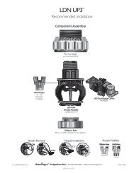
4Installation Options<br />
mini-Wobbler®<br />
1/2 in. (13mm)<br />
Riser Adapter<br />
Flex Tubing<br />
Minimum<br />
Hose Barb<br />
1.5 ft.<br />
Adapter<br />
(45cm) Poly<br />
1/2 in.<br />
Lateral<br />
(13mm)<br />
PVC or<br />
cross<br />
5/16 in.<br />
section<br />
(8mm) Steel Rod<br />
Minimum<br />
1.5 ft.<br />
(45cm)<br />
S.S. Clamps or<br />
UV-Resistant<br />
Nylon Straps<br />
mini-Wobbler®<br />
PVC Female<br />
Adapter<br />
Rubber Hose<br />
Sleeve<br />
Wood Stake or<br />
Steel Rod<br />
1/2 in. (13mm)<br />
of Larger<br />
SCH 40 PVC<br />
4
Xcel-Wobbler ®<br />
5<br />
irrigating<br />
Advantages of a low pressure<br />
(20 psi or 1.38 bar)<br />
Xcel-Wobbler irrigation System<br />
• New balanced design for smooth,<br />
stable operation<br />
• Outstanding uniformity<br />
• Large diameter of coverage at low pressures<br />
• Low wind-drift and evaporative loss<br />
• High-angle model approximately 24° trajectory<br />
(18° trajectory Mid-Angle model also available)<br />
Follow these 4 Steps to design a Xcel-Wobbler irrigation system...<br />
1Determine Application Rate &<br />
2<br />
Maximum length of laterals<br />
Based on the selection of the Xcel-Wobbler HA from Chart A on<br />
page 2, use Table 1 to help determine the application rate and the<br />
maximum length of laterals using PVC (maximum allowable velocity<br />
of 5 ft or 1.52 m per second as recommended by PVC manufacturers).<br />
tAble<br />
tAble 1. Xcel-Wobbler - HA (high Angle)<br />
Maximum Length of Lateral on 25 ft (7.6 m); Spacing at 20 psi (1.38 bar)<br />
1.5" PVC 2" PVC<br />
APPLICAtIOn (1.754 I.D.) (2.193 I.D.)<br />
nOZZLE RAtE Class 160 Class 160<br />
# (in/h) (mm/h) (ft) (m) (ft) (m)<br />
9 0.39 9.91 375 91.4 525 160.0<br />
10 0.48 12.2 325 99.1 450 137.2<br />
11 0.59 15.0 250 76.2 375 114.3<br />
12 0.70 17.8 200 61.0 325 99.1<br />
Data based on
3Determine Spacing<br />
Square Spacing-<br />
Head Spacing: 25 ft (7.62 m)<br />
Row Spacing: 25 ft (7.62 m)<br />
Offset from sides: 5 ft (1.52 m)<br />
Offset from ends: 5 ft (1.52 m)<br />
www.<br />
com<br />
<strong>Senninger</strong>.<br />
Offset<br />
Head Spacing<br />
Single Row Spacing-<br />
Head Spacing: 20 ft (6.10 m)<br />
Offset from sides: 10 ft (3.05 m)<br />
Offset from ends: 5 ft (1.52 m)<br />
Side Offset<br />
Recommended spacings based<br />
on maximum uniformities from<br />
Chart A, page 2.<br />
®<br />
End<br />
Offset<br />
Head Spacing<br />
Row Spacing<br />
irrigating Xcel-Wobbler ®<br />
tAble 3. Xcel-Wobbler - hA (high Angle)<br />
Additional Design Options at 20 psi (1.38 bar) (not shown on Chart A, page 2)<br />
RISER APPLICAtIOn<br />
nOZZLE SquARE SPACIng Cu SC HEIgHt RAtE<br />
# (ft) (m) (%) (in) (cm) (ft) (m)<br />
6 20 x 20 6.10 x 6.10 84.6 1.44 18 45 0.26 6.60<br />
7 20 x 20 6.10 x 6.10 90.7 1.17 18 45 0.36 9.14<br />
8 20 x 20 6.10 x 6.10 8.5 1.19 18 45 0.48 12.2<br />
9 20 x 20 6.10 x 6.10 90.6 1.13 18 45 0.61 15.5<br />
10 20 x 20 6.10 x 6.10 89.1 1.14 18 45 0.76 19.3<br />
Additional Design Options at 25 psi (1.72 bar) (not shown on Chart A, page 2)<br />
RISER APPLICAtIOn<br />
nOZZLE SquARE SPACIng Cu SC HEIgHt RAtE<br />
# (ft) (m) (%) (in) (cm) (ft) (m)<br />
6 25 x 25 7.62 x 7.62 86.9 1.30 18 45 0.19 4.83<br />
7 25 x 25 7.62 x 7.62 86.8 1.30 18 45 0.26 6.60<br />
8 25 x 25 7.62 x 7.62 87.6 1.30 18 45 0.34 8.64<br />
9 25 x 25 7.62 x 7.62 86.1 1.45 18 45 0.44 11.2<br />
10 25 x 25 7.62 x 7.62 86.7 1.30 18 45 0.54 13.7<br />
4<br />
Installation<br />
Option<br />
Female<br />
Adapter<br />
3/4 in. (20mm)<br />
or Larger<br />
SCH 40 PVC<br />
Rubber<br />
Hose Sleeve<br />
S.S. Worm Gear<br />
Clamps Preferred<br />
1/2 in. (13mm)<br />
or Larger<br />
Metal Rod<br />
Minimum<br />
1.0 ft.<br />
(30.5cm)<br />
Xcel-Wobbler®<br />
Minimum<br />
1.5 ft. (45cm)<br />
Maximum<br />
8 ft. (2.5m)<br />
Height<br />
Minimum<br />
1.5 ft. (45cm)<br />
Maximum<br />
8 ft. (2.5m)<br />
Height<br />
6
Smooth Drive <br />
Data based on
3<br />
www.<br />
com<br />
<strong>Senninger</strong>.<br />
Determine Spacing<br />
Square Spacing<br />
Head Spacing: 30 ft (9.14 m)<br />
Row Spacing: 30 ft (9.14 m)<br />
Offset from sides: 10 ft (3.05 m)<br />
Offset from ends: 10 ft (3.05 m)<br />
Head Spacing: 25 ft (7.62 m)<br />
Row Spacing: 25 ft (7.62 m)<br />
Offset from sides: 8 ft (2.44 m)<br />
Offset from ends: 8 ft (2.44 m)<br />
Offset<br />
Head Spacing<br />
Recommended spacings based on maximum<br />
uniformities from Chart A, page 2.<br />
®<br />
Row Spacing<br />
irrigating Smooth Drive <br />
tAble 3. Smooth Drive<br />
Additional Design Options at 25 psi (1.72 bar) (not shown on Chart A, page 2)<br />
RISER APPLICAtIOn<br />
nOZZLE SquARE SPACIng Cu SC HEIgHt RAtE<br />
# (ft) (m) (%) (in) (cm) (ft) (m)<br />
6 25 x 25 7.62 x 7.62 91.8 1.23 18 45 0.19 4.83<br />
7 25 x 25 7.62 x 7.62 95.1 1.10 18 45 0.26 6.60<br />
8 25 x 25 7.62 x 7.62 94.8 1.09 18 45 0.34 8.64<br />
6 30 x 30 9.14 x 9.14 89.6 1.20 18 45 0.13 3.30<br />
7 30 x 30 9.14 x 9.14 89.6 1.23 18 45 0.18 4.57<br />
8 30 x 30 9.14 x 9.14 87.7 1.27 18 45 0.24 6.10<br />
Additional Design Options at 30 psi (2.07 bar) (not shown on Chart A, page 2)<br />
RISER APPLICAtIOn<br />
nOZZLE SquARE SPACIng Cu SC HEIgHt RAtE<br />
# (ft) (m) (%) (in) (cm) (ft) (m)<br />
6 25 x 25 7.62 x 7.62 89.3 1.15 18 45 0.21 5.33<br />
7 25 x 25 7.62 x 7.62 90.6 1.14 18 45 0.28 7.11<br />
8 25 x 25 7.62 x 7.62 89.3 1.17 18 45 0.37 9.40<br />
6 30 x 30 9.14 x 9.14 84.1 1.38 18 45 0.14 3.56<br />
7 30 x 30 9.14 x 9.14 88.0 1.30 18 45 0.20 5.10<br />
8 30 x 30 9.14 x 9.14 89.3 1.35 18 45 0.26 6.60<br />
4 Smooth<br />
Minimum<br />
1.5 ft.(45cm)<br />
S.S. Clamps or<br />
UV-Resistant<br />
Nylon Straps<br />
Installation Options<br />
Drive<br />
PVC Female<br />
Adapter<br />
Wood Stake or<br />
Steel Rod<br />
1/2 in. (13mm)<br />
of Larger<br />
SCH 40 PVC<br />
8
Impact Sprinklers<br />
9<br />
irrigating<br />
Follow these 4 Steps to design an Impact Sprinkler irrigation system...<br />
1Determine Application Rate &<br />
Maximum length of laterals<br />
Based on the selection of an Impact Sprinkler from Chart A on page 2,<br />
use Table 1 to help determine the application rate and the maximum<br />
length of laterals using PVC (maximum allowable velocity of 5 ft or (1.52 mm<br />
tAble<br />
per second) as recommended by PVC manufacturers).<br />
tAble 1. IMPACt SPRINKleRS<br />
Maximum Length of Lateral on 45 ft (3.10 bar)<br />
1.5" PVC<br />
(1.754 I.D.)<br />
Class 160<br />
2" POLy<br />
(2.193 I.D.)<br />
Class 160<br />
SPACIng APPLICAtIOn<br />
EMIttER nOZZLE<br />
RAtE<br />
# (ft) (m) (in/h) (mm/h) (ft) (m) (ft) (m)<br />
2023-1 8SQ 25 7.62 0.46 11.7 350 106.7 500 152.4<br />
3023-2 9RV x 6RV 35 10.7 0.43 10.9 300 91.4 450 137.2<br />
4023-2 12WV x 6RV 40 12.2 0.51 13.0 200 61.0 320 97.5<br />
5023-2 14WV x 8RV 45 13.7 0.54 13.7 180 54.9 300 91.4<br />
Data based on
3<br />
www.<br />
com<br />
<strong>Senninger</strong>.<br />
Determine Spacing<br />
3023-2 Square-<br />
Head Spacing: 35 ft (10.7 m)<br />
Row Spacing: 35 ft (10.7 m)<br />
Offset from sides: 10 ft (3.05 m)<br />
Offset from ends: 10 ft (3.05 m)<br />
Offset<br />
Head Spacing<br />
Recommended spacings based on maximum<br />
uniformities from Chart A, page 2.<br />
4Installation Option<br />
Wood Stake<br />
or Steel Rod<br />
Minimum<br />
1.5 ft. (45cm)<br />
Maximum<br />
8 ft. (2.5m) ht.<br />
Minimum<br />
1.0 ft.(30.5cm)<br />
®<br />
Row Spacing<br />
Impact<br />
Sprinkler<br />
S.S. Clamps or<br />
UV-Resistant<br />
Nylon Straps<br />
irrigating Impact Sprinklers<br />
tAble 3. Impact Sprinklers<br />
Additional Design Options (not shown on Chart A, page 2)<br />
2023-1 Impacts at 45 psi (3.10 bar)<br />
RISER APPLICAtIOn<br />
nOZZLE SquARE SPACIng Cu SC HEIgHt RAtE<br />
# (ft) (m) (%) (in) (cm) (ft) (m)<br />
6Sq 30 x 30 9.14 x 9.14 91.3 1.20 18 45 0.18 4.57<br />
7Sq 30 x 30 9.14 x 9.14 92.3 1.14 18 45 0.24 6.10<br />
8Sq 30 x 30 9.14 x 9.14 92.9 1.13 18 45 0.32 8.13<br />
9WV 30 x 30 9.14 x 9.14 89.3 1.25 18 45 0.40 10.2<br />
3023-2 Impacts at 40 psi (2.76 bar)<br />
7RV x 4RV 40 x 40 12.2 x 12.2 88.7 1.35 18 45 0.21 5.33<br />
8RV x 4RV 40 x 40 12.2 x 12.2 91.8 1.19 18 45 0.27 6.86<br />
9RV x 4RV 40 x 40 12.2 x 12.2 94.8 1.14 18 45 0.31 7.87<br />
10RV x 4RV 40 x 40 12.2 x 12.2 92.3 1.25 18 45 0.27 6.86<br />
4023-2 Impacts at 45 psi (3.10 bar)<br />
10WV x 6RV 55 x 55 16.8 x 16.8 88.2 1.24 18 45 0.20 5.08<br />
11WV x 6RV 55 x 55 16.8 x 16.8 89.5 1.18 18 45 0.24 6.10<br />
12WV x 6RV 55 x 55 16.8 x 16.8 87.5 1.22 18 45 0.29 7.37<br />
13WV x 6RV 55 x 55 16.8 x 16.8 88.2 1.17 18 45 0.31 7.87<br />
14WV x 6RV 55 x 55 16.8 x 16.8 87.4 1.19 18 45 0.35 8.89<br />
5023-2 Impacts at 50 psi (3.45 bar)<br />
13WV x 8RV 65 x 65 19.8 x 19.8 86.9 1.45 18 45 0.24 6.10<br />
14WV x 8RV 65 x 65 19.8 x 19.8 86.9 1.24 18 45 0.28 7.11<br />
15WV x 8RV 65 x 65 19.8 x 19.8 88.0 1.32 18 45 0.30 7.62<br />
16WV x 8RV 65 x 65 19.8 x 19.8 86.3 1.27 18 45 0.34 8.64<br />
17WV x 8RV 65 x 65 19.8 x 19.8 85.7 1.20 18 45 0.37 9.40<br />
10
Pressure Regulators<br />
Other nursery<br />
products:<br />
i-mini-Wobbler<br />
Mister<br />
Part-Circle Impact Sprinklers<br />
Spray Stakes<br />
Super Spray<br />
T-Spray<br />
Wobblers<br />
Made in U.S.A.<br />
16220 E. Highway 50, Clermont, FL 34711<br />
Phone (407) 877-5655<br />
Fax (407) 905-8249 • International Fax (407) 905-8239<br />
Website: www.senninger.com<br />
E-mail: info@senninger.com<br />
12 OIN 05<br />
Pressure Regulators Riser Adapters<br />
Contact <strong>Senninger</strong> <strong>Irrigation</strong> for more<br />
information about these quality products<br />
or the name of your nearest <strong>Senninger</strong><br />
dealer.<br />
®<br />
& Components<br />
Riser Adapter Assemblies<br />
(See our Quick Connect<br />
Riser Adapter Brochure)<br />
Barb Fittings<br />
Bushing Fittings<br />
Punch Tools<br />
0.125" Tubing<br />
For warranty information<br />
see our website. Although<br />
we make every effort<br />
to present accurate<br />
information, <strong>Senninger</strong><br />
reserves the right to<br />
correct any errors or<br />
omissions to this document<br />
without notice.<br />
MS-907