Ag Rotor Installation Manual - Senninger Irrigation
Ag Rotor Installation Manual - Senninger Irrigation
Ag Rotor Installation Manual - Senninger Irrigation

Create successful ePaper yourself
Turn your PDF publications into a flip-book with our unique Google optimized e-Paper software.
<strong>Senninger</strong> Flo-Wise <strong>Ag</strong><strong>Rotor</strong> Flow Sensor<br />
GF/6-3000.090-SI<br />
GF/6-3000.090-SI Rev. C 01/09<br />
SAFETY INSTRUCTIONS<br />
1. Depressurize and vent system prior to installation/removal.<br />
2. Confi rm chemical compatibility before use.<br />
3. Do not exceed maximum temperature/pressure specifi cations.<br />
4. Wear safety goggles or faceshield during installation/service.<br />
5. Do not alter product construction.<br />
1. Description of <strong>Ag</strong><strong>Rotor</strong> Flow Sensor<br />
Page Contents<br />
1. Description<br />
Specifi cations<br />
2. <strong>Installation</strong><br />
3. Mounting and Wiring<br />
4-6. K-Factors<br />
7. Maintenance and Repair<br />
8. Ordering Information<br />
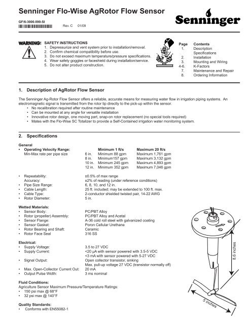
The <strong>Senninger</strong> <strong>Ag</strong>-<strong>Rotor</strong> Flow Sensor offers a reliable, accurate means for measuring water fl ow in irrigation piping systems. An<br />
electromagnetic signal is transmitted from the rotor tip directly to the pick-up within the sensor.<br />
• No recalibration required after routine maintenance<br />
• Can be mounted at any angle for versatile installation<br />
• Innovative rotor design, one moving part, snap-on rotor replacement (no special tools required)<br />
• Mates with the Flo-Wise SC Totalizer to provide a Self-Contained irrigation water monitoring system.<br />
2. Specifi cations<br />
General<br />
• Operating Velocity Range: Minimum 1 ft/s Maximum 20 ft/s<br />
Min-Max rate per pipe size 6 in. Minimum 88 gpm Maximum 1,761 gpm<br />
8 in. Minimum157 gpm Maximum 3,132 gpm<br />
10 in. Minimum 245 gpm Maximum 4,893 gpm<br />
12 in. Minimum 352 gpm Maximum 7,046 gpm<br />
• Repeatability: ±0.5% of max range<br />
Accuracy: ±2% of reading (under reference conditions)<br />
• Pipe Size Range: 6, 8, 10, and 12 in.<br />
• Cable Length: 25 ft. included; may be extended to 100 ft. max.<br />
• Cable Type: 2-conductor shielded twisted pair, 14-22 AWG<br />
• <strong>Rotor</strong> Diameter: 5 in.<br />
Wetted Materials:<br />
• Sensor Body: PC/PBT Alloy<br />
• <strong>Rotor</strong> (propeller) Assembly: PC/PBT Alloy and Acetal<br />
• Sensor Flange: A-36 cold roll steel with galvanized coating<br />
• Sensor Gasket: Poron Cellular Urethane<br />
• <strong>Rotor</strong> Bearing and Shaft: Ceramic<br />
• <strong>Rotor</strong> Face Seal 316 SS<br />
Electrical:<br />
• Supply Voltage: 3.5 to 27 VDC<br />
• Supply Current:
3. <strong>Installation</strong><br />
3.1 Location<br />
• Select a location where the pipe will always be full.<br />
• The pipe must be straight and uninterrupted for at least<br />
ten pipe diameters before the sensor. Five diameters are<br />
acceptable ONLY after a simple 90 degree elbow.<br />
3.2 Saddle <strong>Installation</strong><br />
1. Drill a 2.5 inch hole in the pipe. Deburr the cut edges to<br />
prevent damage to the saddle gasket.<br />
2. Measure and record the inside diameter (ID) of the pipe as<br />
illustrated. This will be used later to determine the K-factor<br />
for system calibration.<br />
3. Place the fl anged fi tting half of the strap-on saddle over the<br />
hole. Ensure that the alignment hole on the upper saddle<br />
fl ange is pointing downstream.<br />
4. Place the lower half of saddle onto pipe and tighten the<br />
bolts to no more than 65 foot-pounds.<br />
NOTE: <strong>Installation</strong> fi ttings may be fabricated using the<br />
dimensional drawings below. The fl ange height is critical to<br />
the accuracy of the measurement!<br />
3.3 Sensor <strong>Installation</strong><br />
1. Install sensor into pipe with alignment pin downstream.<br />
2. Place the base plate for the outer cover over the sensor<br />
fl ange.<br />
2. Bolt the assembly securely with the hardware provided.<br />
3. Install the conduit base gasket onto the top of the sensor.<br />
4. Position the conduit base over the top of the sensor and<br />
thread the sensor wires through the conduit base.<br />
5. Press the conduit base down on the top of the sensor tube<br />
aligning the cutout keys and press down until it seats.<br />
6. Turn the conduit base ¼-turn clockwise to secure it to the<br />
sensor.<br />
Note: The conduit base can be aligned in four directions.<br />
7. Thread sensor wires through the locking ring. Insert locking<br />
ring into the conduit base, aligning it so that the square tab<br />
is close to the wire ports.<br />
2<br />
Ø 2.50 thru<br />
60° typical<br />
8.38<br />
2.5<br />
Downstream<br />
Flange bolt pattern<br />
Flanged outlet height<br />
Ø 0.265 thru<br />
2.123<br />
weld<br />
All dimensions in inches<br />
Ø 5.00 thru<br />
6x Ø 0.375 thru<br />
on 4.250 Ø center<br />
0.38 in. thick<br />
minimum cold<br />
rolled steel or<br />
stronger<br />
recommended<br />
centerline of pipe<br />
Pipe Inside<br />
Diameter (ID)<br />
Alignment hole<br />
90° Elbow<br />
Ruler or Scale<br />
Flow<br />
Locking Ring<br />
Conduit Base<br />
Conduit base gasket<br />
MINIMUM<br />
5 x Diameter<br />
2.5" dia.<br />
hole<br />
FLO-WISE FLO-WISE SC SC<br />
Saddle<br />
SENNINGER<br />
SENNINGER<br />
ENTER ENTER<br />
#6 x1/4" hold-down screw<br />
Locking Ring<br />
HOLD-DOWN SCREW<br />
screws into the Conduit<br />
Base so the screw head<br />
rests on top of the Locking<br />
Ring.<br />
2-inch Bolts<br />
(6 ea.)<br />
Washers<br />
(12 ea.)<br />
Nuts (6 ea.)<br />
Diameter<br />
Inside Diameter:<br />
_____________ in.
4. Connecting the Instrument<br />
Mounting with Integral Instrument<br />
No additional hardware is required to mount the Flo-Wise SC or<br />
the Flo-Wise AO directly onto the Flo-Wise <strong>Ag</strong><strong>Rotor</strong>.<br />
Cut the excess cable on the <strong>Ag</strong><strong>Rotor</strong> sensor and connect directly<br />
to the terminals of the instrument.<br />
The white outer cover protects the Flo-Wise<br />
instrument from the elements. More detailed<br />
assembly instructions are provided with the<br />
cover.<br />
Mounting with Remote Instrument<br />
The conduit base cover and Universal Mounting kit must be ordered<br />
separately to connect the <strong>Ag</strong><strong>Rotor</strong> to a remote instrument.<br />
• The <strong>Ag</strong><strong>Rotor</strong> includes 25 ft. of cable that may be extended if<br />
necessary to a maximum of 100 ft. to the Flo-Wise SC.<br />
• The cable can be extended to 1000 ft. if the <strong>Ag</strong><strong>Rotor</strong> sensor is<br />
connected to the Flo-Wise AO.<br />
Flo-Wise SC<br />
Terminals<br />
1<br />
2<br />
3<br />
4<br />
5<br />
6<br />
White<br />
Red<br />
Black<br />
FLO-WISE FLO-WISE SC SC<br />
SENNINGER<br />
SENNINGER<br />
ENTER ENTER<br />
White<br />
Red<br />
Black<br />
4<br />
3<br />
2<br />
1<br />
Mounting<br />
Screw<br />
Locking<br />
Ring<br />
Conduit<br />
Base<br />
10<br />
9<br />
8<br />
7<br />
6<br />
5<br />
5<br />
13<br />
12<br />
11<br />
GF/6-8550-2-SI<br />
Flo-Wise AO<br />
GF/6-3113-SI<br />
Conduit base Cover<br />
Conduit Base<br />
Conduit base<br />
gasket<br />
Flo-Wise AO<br />
Terminals<br />
13<br />
12<br />
11<br />
Do not use this hole.<br />
Square Tab<br />
The Mounting Screw for the<br />
Locking Ring goes into the Conduit<br />
Base (not the Locking Ring) -- the<br />
screw head rests on the lip of the<br />
Locking Ring<br />
Conduit<br />
Ports<br />
Flo-Wise SC<br />
(GF/6-8150-1-SI)<br />
Flo-Wise AO<br />
(GF/6-8550-2-SI)<br />
GF/6-8150-1-SI<br />
Flo-Wise SC<br />
Sensr Gnd<br />
(SHIELD)<br />
Sensr IN<br />
(RED)<br />
Sensr V+<br />
(BLACK)<br />
Universal<br />
Mounting kit<br />
(GF/3-8050)<br />
Liquid-tight<br />
Connectors<br />
(GF/3-9000.392-1)<br />
Maximum cable length to SC: 100 ft.<br />
Maximum cable length to AO: 1000 ft.<br />
3
5. K-Factors<br />
K-factors are calibration constants, defi ned as the number of pulses generated by the rotor for each measure (gallon, acre-inch, etc.) of<br />
water that passes by the sensor. The following tables provide the K-factor for pipe sizes from 5.5 in. diameter to 12.6 inches diameter.<br />
After selecting the value that matches the installation, it must be entered into the program of the <strong>Senninger</strong> Flo-Wise instrument. This<br />
information enables the instrument to correctly interpret the pulses coming from the <strong>Ag</strong><strong>Rotor</strong> to display the fl ow rate and total fl ow<br />
volume.<br />
The instruction manuals supplied with the <strong>Senninger</strong> Flo-Wise SC Totalizer and the <strong>Senninger</strong> Flo-Wise AO Flow Transmitter include<br />
complete information for using the K-factor.<br />
How to Select Your K-Factor<br />
1. Locate the column in the following tables that represents the inside diameter (ID) of your pipe.<br />
2. Measure the distance (in inches) from the nearest elbow upstream of the sensor.<br />
3. Find where the ID column and Distance From Elbow row intersect. This is your K-Factor setting.<br />
If a valve, tee or pump is located immediately<br />
upstream of the sensor, the minimum<br />
distance is 10 x Diameter.<br />
Always provide as much straight run as<br />
possible for best performance.<br />
90° Elbow<br />
MINIMUM<br />
5 x Diameter<br />
Saddle<br />
Diameter<br />
K-Factors for Sensor in 6 inch Pipe Downstream from a 90 degree elbow (mitered or smooth)<br />
Pipe ID 5.5 5.6 5.7 5.8 5.9 6 6.065 6.1 6.2 6.3 6.4 6.5<br />
distance Sched<br />
from elbow K factors (pulses per US gallon) 40<br />
(inches)<br />
30 3.135 3.045 2.955 2.865 2.775 2.685 2.627 2.595 2.505 2.415 2.326 2.236<br />
40 3.210 3.118 3.026 2.934 2.841 2.749 2.689 2.657 2.564 2.472 2.380 2.288<br />
50 3.272 3.178 3.084 2.990 2.896 2.802 2.740 2.707 2.613 2.519 2.425 2.331<br />
60 3.321 3.226 3.130 3.035 2.940 2.844 2.782 2.749 2.654 2.558 2.463 2.367<br />
70 3.361 3.264 3.168 3.072 2.975 2.879 2.816 2.783 2.686 2.590 2.494 2.398<br />
80 3.392 3.295 3.198 3.101 3.004 2.907 2.844 2.810 2.713 2.616 2.519 2.422<br />
90 3.416 3.319 3.221 3.124 3.027 2.929 2.866 2.832 2.735 2.637 2.540 2.443<br />
100 3.435 3.337 3.240 3.142 3.045 2.947 2.884 2.849 2.752 2.654 2.557 2.459<br />
110 3.449 3.352 3.254 3.156 3.059 2.961 2.897 2.863 2.766 2.668 2.570 2.472<br />
120 3.461 3.363 3.265 3.167 3.070 2.972 2.908 2.874 2.776 2.679 2.581 2.483<br />
130 3.469 3.371 3.274 3.176 3.078 2.980 2.917 2.883 2.785 2.687 2.589 2.492<br />
140 3.476 3.378 3.280 3.182 3.085 2.987 2.923 2.889 2.791 2.694 2.596 2.498<br />
150 3.481 3.383 3.285 3.188 3.090 2.992 2.929 2.894 2.797 2.699 2.601 2.504<br />
160 3.485 3.387 3.289 3.192 3.094 2.996 2.933 2.899 2.801 2.703 2.606 2.508<br />
170 3.489 3.391 3.293 3.195 3.098 3.000 2.936 2.902 2.804 2.707 2.609 2.511<br />
180 3.492 3.395 3.297 3.199 3.101 3.003 2.940 2.905 2.808 2.710 2.612 2.514<br />
190 3.496 3.398 3.300 3.202 3.104 3.006 2.943 2.908 2.810 2.712 2.614 2.516<br />
200 3.502 3.403 3.305 3.207 3.108 3.010 2.946 2.912 2.813 2.715 2.617 2.518<br />
210 3.508 3.409 3.310 3.212 3.113 3.014 2.950 2.915 2.817 2.718 2.619 2.521<br />
220 3.508 3.409 3.310 3.212 3.113 3.014 2.950 2.915 2.817 2.718 2.619 2.521<br />
230 3.508 3.409 3.310 3.212 3.113 3.014 2.950 2.915 2.817 2.718 2.619 2.521<br />
240 3.508 3.409 3.310 3.212 3.113 3.014 2.950 2.915 2.817 2.718 2.619 2.521<br />
To convert from Pulses per Gallon To:<br />
Pulses per Liter Divide the chart value by 3.785<br />
Pulses per Acre-Inch Multiply the chart value by 27154<br />
Pulses per Cubic Meter (Metric Tonne) Multiply the chart value by 264.2<br />
4
K-Factors for Sensor in 8 inch Pipe Downstream from a 90 degree elbow (mitered or smooth)<br />
ID(in) 7.5 7.6 7.7 7.8 7.9 7.961 8 8.1 8.2 8.3 8.4 8.5<br />
distance Sched<br />
from elbow K factors (pulses per US gallon) 40<br />
(inches)<br />
40 1.745 1.704 1.664 1.623 1.583 1.558 1.542 1.501 1.461 1.420 1.379 1.339<br />
50 1.777 1.735 1.694 1.652 1.611 1.586 1.570 1.528 1.487 1.445 1.404 1.362<br />
60 1.804 1.762 1.720 1.678 1.636 1.610 1.593 1.551 1.509 1.467 1.425 1.383<br />
70 1.827 1.784 1.742 1.699 1.657 1.631 1.614 1.571 1.529 1.486 1.443 1.401<br />
80 1.847 1.804 1.761 1.718 1.675 1.648 1.632 1.588 1.545 1.502 1.459 1.416<br />
90 1.863 1.820 1.777 1.733 1.690 1.663 1.647 1.603 1.560 1.517 1.473 1.430<br />
100 1.877 1.834 1.790 1.747 1.703 1.676 1.659 1.616 1.572 1.529 1.485 1.441<br />
110 1.889 1.845 1.801 1.758 1.714 1.687 1.670 1.626 1.583 1.539 1.495 1.451<br />
120 1.899 1.855 1.811 1.767 1.723 1.696 1.679 1.635 1.592 1.548 1.504 1.460<br />
130 1.907 1.863 1.819 1.775 1.731 1.704 1.687 1.643 1.599 1.555 1.511 1.467<br />
140 1.913 1.869 1.825 1.781 1.737 1.711 1.693 1.649 1.605 1.561 1.517 1.473<br />
150 1.919 1.875 1.831 1.787 1.743 1.716 1.699 1.655 1.611 1.567 1.523 1.479<br />
160 1.923 1.879 1.835 1.791 1.747 1.720 1.703 1.659 1.615 1.571 1.527 1.483<br />
170 1.927 1.883 1.839 1.795 1.751 1.724 1.707 1.663 1.619 1.575 1.531 1.487<br />
180 1.930 1.886 1.842 1.798 1.754 1.727 1.710 1.666 1.622 1.578 1.534 1.490<br />
190 1.932 1.888 1.844 1.800 1.756 1.730 1.712 1.668 1.624 1.580 1.536 1.492<br />
200 1.935 1.891 1.847 1.803 1.759 1.732 1.715 1.671 1.627 1.583 1.539 1.495<br />
210 1.936 1.892 1.848 1.804 1.760 1.734 1.716 1.672 1.628 1.584 1.540 1.496<br />
220 1.938 1.894 1.850 1.806 1.762 1.735 1.718 1.674 1.630 1.586 1.542 1.498<br />
230 1.940 1.896 1.852 1.808 1.763 1.737 1.719 1.675 1.631 1.587 1.543 1.499<br />
240 1.941 1.897 1.853 1.809 1.765 1.738 1.721 1.677 1.633 1.589 1.545 1.500<br />
250 1.943 1.899 1.855 1.810 1.766 1.739 1.722 1.678 1.634 1.590 1.546 1.502<br />
260 1.945 1.901 1.856 1.812 1.768 1.741 1.724 1.679 1.635 1.591 1.547 1.502<br />
270 1.947 1.903 1.858 1.814 1.770 1.743 1.725 1.681 1.636 1.592 1.548 1.503<br />
280 1.950 1.905 1.861 1.816 1.772 1.744 1.727 1.683 1.638 1.593 1.549 1.504<br />
290 1.953 1.908 1.864 1.819 1.774 1.747 1.729 1.684 1.640 1.595 1.550 1.505<br />
300 1.957 1.912 1.867 1.822 1.777 1.749 1.732 1.687 1.642 1.597 1.552 1.507<br />
K-Factors for Sensor in 10 inch Pipe Downstream from a 90 degree elbow (mitered or smooth)<br />
ID(in) 9.5 9.6 9.7 9.8 9.9 10.02 10.1 10.2 10.3 10.4 10.5 11<br />
distance Sched<br />
from elbow K factors (pulses per US gallon) 40<br />
(inches)<br />
50 1.088 1.067 1.047 1.026 1.005 0.981 0.964 0.944 0.923 0.903 0.882 0.779<br />
60 1.109 1.088 1.067 1.046 1.025 1.000 0.983 0.962 0.941 0.920 0.899 0.794<br />
70 1.128 1.107 1.085 1.064 1.042 1.017 1.000 0.978 0.957 0.935 0.914 0.807<br />
80 1.145 1.123 1.101 1.079 1.058 1.032 1.014 0.993 0.971 0.949 0.927 0.819<br />
90 1.159 1.137 1.115 1.093 1.071 1.045 1.027 1.005 0.983 0.961 0.940 0.830<br />
100 1.172 1.150 1.128 1.106 1.083 1.057 1.039 1.017 0.995 0.972 0.950 0.839<br />
110 1.184 1.161 1.139 1.117 1.094 1.067 1.049 1.027 1.005 0.982 0.960 0.848<br />
120 1.194 1.171 1.149 1.126 1.104 1.077 1.059 1.036 1.014 0.991 0.968 0.856<br />
130 1.203 1.180 1.157 1.135 1.112 1.085 1.067 1.044 1.021 0.999 0.976 0.863<br />
140 1.211 1.188 1.165 1.142 1.120 1.092 1.074 1.051 1.028 1.006 0.983 0.869<br />
150 1.217 1.195 1.172 1.149 1.126 1.099 1.080 1.058 1.035 1.012 0.989 0.875<br />
160 1.224 1.201 1.178 1.155 1.132 1.104 1.086 1.063 1.040 1.017 0.995 0.880<br />
170 1.229 1.206 1.183 1.160 1.137 1.110 1.091 1.068 1.045 1.022 0.999 0.885<br />
180 1.234 1.211 1.188 1.165 1.142 1.114 1.096 1.073 1.050 1.027 1.004 0.889<br />
190 1.238 1.215 1.192 1.169 1.146 1.118 1.100 1.077 1.054 1.031 1.008 0.893<br />
200 1.241 1.218 1.195 1.172 1.149 1.122 1.103 1.080 1.057 1.034 1.011 0.896<br />
210 1.244 1.221 1.198 1.175 1.152 1.125 1.106 1.083 1.060 1.037 1.014 0.899<br />
220 1.247 1.224 1.201 1.178 1.155 1.127 1.109 1.086 1.063 1.040 1.017 0.902<br />
230 1.249 1.226 1.203 1.180 1.157 1.130 1.111 1.088 1.065 1.042 1.019 0.904<br />
240 1.251 1.228 1.205 1.182 1.159 1.131 1.113 1.090 1.067 1.044 1.021 0.906<br />
250 1.252 1.229 1.206 1.184 1.161 1.133 1.115 1.092 1.069 1.046 1.023 0.908<br />
260 1.254 1.231 1.208 1.185 1.162 1.134 1.116 1.093 1.070 1.047 1.024 0.909<br />
270 1.254 1.232 1.209 1.186 1.163 1.135 1.117 1.094 1.071 1.048 1.025 0.911<br />
280 1.255 1.232 1.209 1.186 1.164 1.136 1.118 1.095 1.072 1.049 1.026 0.912<br />
290 1.256 1.233 1.210 1.187 1.164 1.137 1.119 1.096 1.073 1.050 1.027 0.913<br />
300 1.256 1.233 1.210 1.188 1.165 1.137 1.119 1.096 1.073 1.051 1.028 0.913<br />
310 1.257 1.234 1.211 1.188 1.165 1.138 1.120 1.097 1.074 1.051 1.028 0.914<br />
320 1.257 1.234 1.212 1.189 1.166 1.138 1.120 1.097 1.074 1.051 1.028 0.914<br />
5
K-Factors for Sensor in 12 inch Pipe Downstream from a 90 degree elbow (mitered or smooth)<br />
ID(in) 11.5 11.6 11.7 11.8 11.9 12 12.1 12.2 12.3 12.4 12.5 12.6<br />
distance Sched<br />
from elbow K factors (pulses per US gallon) 40<br />
(inches)<br />
60 0.791 0.778 0.765 0.753 0.740 0.727 0.714 0.702 0.689 0.676 0.663 0.651<br />
70 0.803 0.790 0.777 0.764 0.751 0.738 0.725 0.712 0.699 0.686 0.673 0.660<br />
80 0.814 0.801 0.788 0.775 0.762 0.748 0.735 0.722 0.709 0.696 0.683 0.669<br />
90 0.824 0.811 0.797 0.784 0.771 0.758 0.744 0.731 0.718 0.704 0.691 0.678<br />
100 0.833 0.820 0.806 0.793 0.779 0.766 0.752 0.739 0.725 0.712 0.699 0.685<br />
110 0.841 0.828 0.814 0.800 0.787 0.773 0.760 0.746 0.733 0.719 0.705 0.692<br />
120 0.849 0.835 0.821 0.807 0.794 0.780 0.766 0.753 0.739 0.725 0.712 0.698<br />
130 0.855 0.841 0.828 0.814 0.800 0.786 0.772 0.759 0.745 0.731 0.717 0.704<br />
140 0.861 0.847 0.833 0.820 0.806 0.792 0.778 0.764 0.750 0.736 0.723 0.709<br />
150 0.866 0.853 0.839 0.825 0.811 0.797 0.783 0.769 0.755 0.741 0.727 0.713<br />
160 0.871 0.857 0.843 0.829 0.815 0.801 0.787 0.774 0.760 0.746 0.732 0.718<br />
170 0.876 0.862 0.848 0.834 0.820 0.806 0.792 0.778 0.764 0.750 0.736 0.722<br />
180 0.880 0.866 0.851 0.837 0.823 0.809 0.795 0.781 0.767 0.753 0.739 0.725<br />
190 0.883 0.869 0.855 0.841 0.827 0.813 0.799 0.785 0.770 0.756 0.742 0.728<br />
200 0.886 0.872 0.858 0.844 0.830 0.816 0.802 0.788 0.773 0.759 0.745 0.731<br />
210 0.889 0.875 0.861 0.847 0.833 0.819 0.804 0.790 0.776 0.762 0.748 0.734<br />
220 0.892 0.878 0.863 0.849 0.835 0.821 0.807 0.793 0.779 0.764 0.750 0.736<br />
230 0.894 0.880 0.866 0.852 0.837 0.823 0.809 0.795 0.781 0.767 0.753 0.738<br />
240 0.896 0.882 0.868 0.854 0.839 0.825 0.811 0.797 0.783 0.769 0.754 0.740<br />
250 0.898 0.884 0.869 0.855 0.841 0.827 0.813 0.799 0.785 0.770 0.756 0.742<br />
260 0.899 0.885 0.871 0.857 0.843 0.829 0.814 0.800 0.786 0.772 0.758 0.744<br />
270 0.901 0.887 0.872 0.858 0.844 0.830 0.816 0.802 0.788 0.773 0.759 0.745<br />
280 0.902 0.888 0.874 0.859 0.845 0.831 0.817 0.803 0.789 0.775 0.761 0.746<br />
290 0.903 0.889 0.875 0.860 0.846 0.832 0.818 0.804 0.790 0.776 0.762 0.748<br />
300 0.904 0.890 0.875 0.861 0.847 0.833 0.819 0.805 0.791 0.777 0.763 0.749<br />
310 0.904 0.890 0.876 0.862 0.848 0.834 0.820 0.806 0.792 0.778 0.763 0.749<br />
320 0.905 0.891 0.877 0.863 0.849 0.835 0.820 0.806 0.792 0.778 0.764 0.750<br />
330 0.905 0.891 0.877 0.863 0.849 0.835 0.821 0.807 0.793 0.779 0.765 0.751<br />
340 0.906 0.892 0.878 0.864 0.850 0.835 0.821 0.807 0.793 0.779 0.765 0.751<br />
350 0.906 0.892 0.878 0.864 0.850 0.836 0.822 0.808 0.794 0.780 0.766 0.752<br />
360 0.906 0.892 0.878 0.864 0.850 0.836 0.822 0.808 0.794 0.780 0.766 0.752<br />
370 0.907 0.893 0.878 0.864 0.850 0.836 0.822 0.808 0.794 0.780 0.766 0.752<br />
380 0.907 0.893 0.879 0.865 0.851 0.837 0.823 0.809 0.795 0.781 0.766 0.752<br />
390 0.907 0.893 0.879 0.865 0.851 0.837 0.823 0.809 0.795 0.781 0.767 0.753<br />
400 0.908 0.894 0.880 0.866 0.851 0.837 0.823 0.809 0.795 0.781 0.767 0.753<br />
410 0.909 0.895 0.880 0.866 0.852 0.838 0.824 0.810 0.795 0.781 0.767 0.753<br />
420 0.910 0.895 0.881 0.867 0.853 0.839 0.824 0.810 0.796 0.782 0.767 0.753<br />
To convert the K-factor from Pulses per Gallon To:<br />
Pulses per Liter Divide the chart value by 3.785<br />
Pulses per Acre-Inch Multiply the chart value by 27154<br />
Pulses per Cubic Meter (Metric Tonne) Multiply the chart value by 264.2<br />
6
6. Maintenance and Repair<br />
At least once a season, remove the fl ow sensor to check for wear.<br />
High fl ow rates, debris and dirty water increase wear and require<br />
more frequent inspection.<br />
6.1 Sensor Removal<br />
1. Turn off pump.<br />
Depressurize and vent system prior to prior to<br />
performing the following procedure.<br />
2. Turn off relief valve and drain the pipe.<br />
3. Loosen and remove bolts, nuts and washers securing<br />
sensor to the installation fi tting.<br />
FLO-WISE FLO-WISE SC SC<br />
SENNINGER<br />
SENNINGER<br />
4. Lift and tilt the sensor slightly until you feel the rotor blade<br />
contact the inner pipe wall.<br />
5. Gently lift and tilt sensor to align rotor blade for removal.<br />
CAUTION: DO NOT FORCE! If resistance is felt while lifting<br />
sensor, repeat sequence until sensor can be removed without<br />
damaging it.<br />
ENTER ENTER<br />
Note: If necessary, use a wire or stick to help<br />
reposition the rotor for removal.<br />
5<br />
6.2 <strong>Rotor</strong> Inspection<br />
1. <strong>Rotor</strong> Rotation: Flick the rotor to check that it is "free<br />
spinning" and not bound or slow in rotating. If bearing<br />
binds, replace rotor assembly (P/N GF/6-3000.390-SI).<br />
1 2 3<br />
2. Bearing Gap: Grasp rotor and shaft and gently try to<br />
pull them apart. If there is a gap of more than 0.10-inch,<br />
replace rotor kit (P/N GF/6-3000.390-SI).<br />
3. Wobble: Wobble rotor blade from side-to-side. If blade<br />
wobbles more than 0.10-inch, replace rotor kit<br />
(P/N GF/6-3000.090-SI).<br />
6.3 <strong>Rotor</strong> Replacement<br />
1/10" max<br />
1. Insert a small screwdriver or coin under rotor retaining clip<br />
to release the rotor assembly from sensor body.<br />
Insert screwdriver tip under rotor<br />
retainer clip until rotor assembly<br />
releases from sensor body.<br />
2. Gently separate halves. DO NOT overextend the rotor<br />
assembly retaining clip or it will break.<br />
Sensor body<br />
Gently separate<br />
sensor halves.<br />
<strong>Rotor</strong> assembly<br />
GF/6-3000.390-SI<br />
Screwdriver<br />
<strong>Rotor</strong> retaining clip<br />
3. Reinstall sensor rotor asembly in reverse order. Assembly<br />
is keyed for proper orientation. When properly seated on<br />
the sensor body the retainer clip will "click" into position.<br />
7
7. Ordering Information for <strong>Senninger</strong> Flo-Wise SC <strong>Ag</strong><strong>Rotor</strong> System<br />
Order three parts for a complete<br />
Flo-Wise SC <strong>Ag</strong><strong>Rotor</strong> system:<br />
RA RATE TE UNITS UNITS<br />
TOT OTALIZER ALIZER UNITS UNITS<br />
GALLONS GALLONS<br />
GALLONS GALLONS X X 1,000 1,000<br />
Velcro elcro<br />
Velcro elcro<br />
MODEL: MODEL: 4-3100 4-3100<br />
patch patch<br />
patch patch<br />
pipe pipe size, size, ID. ID. Model Model No. No.<br />
SN: SN: 69908162437<br />
69908162437<br />
+GF+ +GF+ SIGNET SIGNET<br />
8" 8"<br />
4-3100.610.A-5/99<br />
4-3100.610.A-5/99<br />
ENTER<br />
1.<br />
2.<br />
3.<br />
GF/6-3100-SI<br />
Flo-Wise SC Totalizer<br />
with Outer Cover Assembly<br />
Flow-Wise SC is a battery<br />
powered instrument that<br />
provides fl ow rate and total fl ow<br />
information. It mates with the<br />
Flo-Wise <strong>Ag</strong><strong>Rotor</strong> fl ow sensor<br />
for a completely self-contained<br />
irrigation monitoring system.<br />
GF/6-3000-5-SI<br />
Flo-Wise <strong>Ag</strong><strong>Rotor</strong> Sensor<br />
(Minimum pipe size 6 inches)<br />
<strong>Senninger</strong> <strong>Irrigation</strong>, Inc.<br />
16220 E. Highway 50<br />
Clermont, FL 34711 U.S.A.<br />
Phone: (407) 293-5555 • Fax: (407) 293-5740<br />
www. senninger.com • e-mail: info@senninger.com<br />
Strap-on Saddle w/flange<br />
(Weld-on flanges also available.<br />
Call <strong>Senninger</strong> for other installation options.)<br />
JC/410PG-0663X16IP 6 inch saddle, epoxy<br />
JC/410PG-0863X16 8 inch saddle, epoxy<br />
JC/410PG-1075X16IP 10 inch saddle, epoxy<br />
JC/410PG-1275X16IP 12 inch saddle, epoxy<br />
Optional<br />
Flo-Wise AO mates with the Flo-Wise <strong>Ag</strong><strong>Rotor</strong><br />
sensor for applications requiring more than basic<br />
monitoring capability.<br />
It is a 24 VDC instrument that provides fl ow rate<br />
and total fl ow, plus two output functions:<br />
• 4-20 mA loop for chart recorders and<br />
datalogging systems<br />
• Two dry-contact relays for alarm or control<br />
functions.<br />
Flow 6.25 GPM<br />
Total 1234567.8><br />
ENTER<br />
GF/6-8550-2-SI<br />
Flo-Wise AO<br />
Transmitter<br />
Spare Parts and Accessories<br />
Part No. Description<br />
GF/6-3000.390-SI Replacement rotor assembly, <strong>Ag</strong><strong>Rotor</strong><br />
GF/6-3113-SI Conduit base Cover<br />
Printed in USA on recycled paper