Ag Rotor Installation Manual - Senninger Irrigation
Ag Rotor Installation Manual - Senninger Irrigation
Ag Rotor Installation Manual - Senninger Irrigation

You also want an ePaper? Increase the reach of your titles
YUMPU automatically turns print PDFs into web optimized ePapers that Google loves.
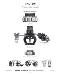
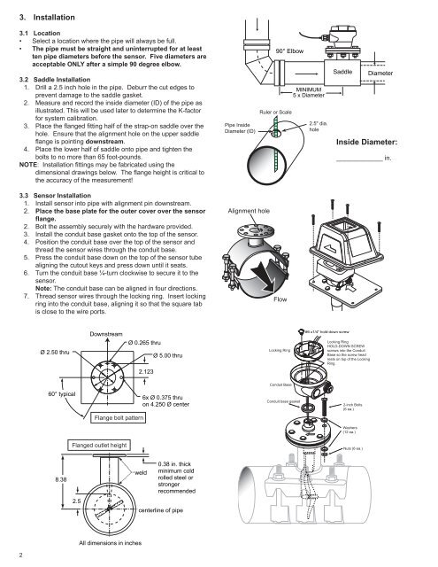
3. <strong>Installation</strong><br />
3.1 Location<br />
• Select a location where the pipe will always be full.<br />
• The pipe must be straight and uninterrupted for at least<br />
ten pipe diameters before the sensor. Five diameters are<br />
acceptable ONLY after a simple 90 degree elbow.<br />
3.2 Saddle <strong>Installation</strong><br />
1. Drill a 2.5 inch hole in the pipe. Deburr the cut edges to<br />
prevent damage to the saddle gasket.<br />
2. Measure and record the inside diameter (ID) of the pipe as<br />
illustrated. This will be used later to determine the K-factor<br />
for system calibration.<br />
3. Place the fl anged fi tting half of the strap-on saddle over the<br />
hole. Ensure that the alignment hole on the upper saddle<br />
fl ange is pointing downstream.<br />
4. Place the lower half of saddle onto pipe and tighten the<br />
bolts to no more than 65 foot-pounds.<br />
NOTE: <strong>Installation</strong> fi ttings may be fabricated using the<br />
dimensional drawings below. The fl ange height is critical to<br />
the accuracy of the measurement!<br />
3.3 Sensor <strong>Installation</strong><br />
1. Install sensor into pipe with alignment pin downstream.<br />
2. Place the base plate for the outer cover over the sensor<br />
fl ange.<br />
2. Bolt the assembly securely with the hardware provided.<br />
3. Install the conduit base gasket onto the top of the sensor.<br />
4. Position the conduit base over the top of the sensor and<br />
thread the sensor wires through the conduit base.<br />
5. Press the conduit base down on the top of the sensor tube<br />
aligning the cutout keys and press down until it seats.<br />
6. Turn the conduit base ¼-turn clockwise to secure it to the<br />
sensor.<br />
Note: The conduit base can be aligned in four directions.<br />
7. Thread sensor wires through the locking ring. Insert locking<br />
ring into the conduit base, aligning it so that the square tab<br />
is close to the wire ports.<br />
2<br />
Ø 2.50 thru<br />
60° typical<br />
8.38<br />
2.5<br />
Downstream<br />
Flange bolt pattern<br />
Flanged outlet height<br />
Ø 0.265 thru<br />
2.123<br />
weld<br />
All dimensions in inches<br />
Ø 5.00 thru<br />
6x Ø 0.375 thru<br />
on 4.250 Ø center<br />
0.38 in. thick<br />
minimum cold<br />
rolled steel or<br />
stronger<br />
recommended<br />
centerline of pipe<br />
Pipe Inside<br />
Diameter (ID)<br />
Alignment hole<br />
90° Elbow<br />
Ruler or Scale<br />
Flow<br />
Locking Ring<br />
Conduit Base<br />
Conduit base gasket<br />
MINIMUM<br />
5 x Diameter<br />
2.5" dia.<br />
hole<br />
FLO-WISE FLO-WISE SC SC<br />
Saddle<br />
SENNINGER<br />
SENNINGER<br />
ENTER ENTER<br />
#6 x1/4" hold-down screw<br />
Locking Ring<br />
HOLD-DOWN SCREW<br />
screws into the Conduit<br />
Base so the screw head<br />
rests on top of the Locking<br />
Ring.<br />
2-inch Bolts<br />
(6 ea.)<br />
Washers<br />
(12 ea.)<br />
Nuts (6 ea.)<br />
Diameter<br />
Inside Diameter:<br />
_____________ in.