KRIEGERS FLAK OWF GEOPHYSICAL SURVEY ... - Energinet.dk
KRIEGERS FLAK OWF GEOPHYSICAL SURVEY ... - Energinet.dk
KRIEGERS FLAK OWF GEOPHYSICAL SURVEY ... - Energinet.dk

You also want an ePaper? Increase the reach of your titles
YUMPU automatically turns print PDFs into web optimized ePapers that Google loves.
Intended for<br />
<strong>Energinet</strong>.<strong>dk</strong><br />
Document type<br />
Geophysical Survey Results<br />
Date<br />
August, 2013<br />
Clients Ref.:<br />
1000/12<br />
Project<br />
<strong>KRIEGERS</strong> <strong>FLAK</strong> & HORNS REV 3 – GEO INVESTIGATIONS 2012<br />
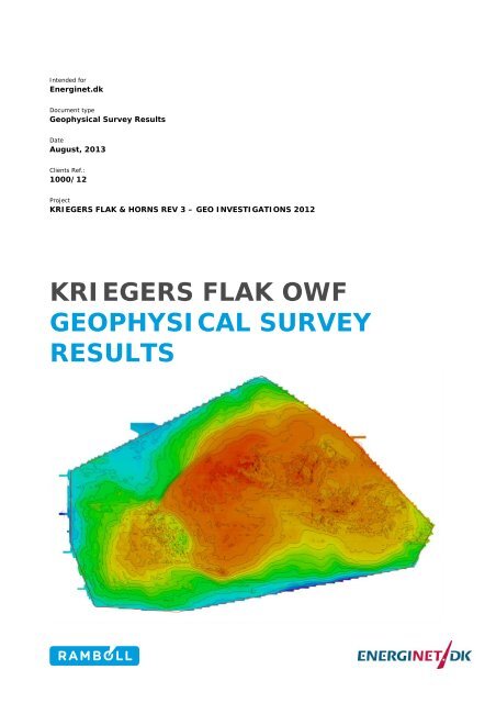
<strong>KRIEGERS</strong> <strong>FLAK</strong> <strong>OWF</strong><br />
<strong>GEOPHYSICAL</strong> <strong>SURVEY</strong><br />
RESULTS
<strong>KRIEGERS</strong> <strong>FLAK</strong> <strong>OWF</strong><br />
<strong>GEOPHYSICAL</strong> <strong>SURVEY</strong> RESULTS<br />
Revision 4<br />
Date 15/08/2013<br />
Made by JS, HEH, LGG, NLR<br />
Checked by RUBJ, JRV, PPL<br />
Approved by UTN<br />
Description Geophysical Survey Results<br />
Clients Ref.: 1000/12<br />
Project Kriegers Flak & Horns Rev 3 - Geo Investigations 2012<br />
Ref<br />
KF_<strong>OWF</strong>_Geophysical_Survey_Results_v4.docx<br />
Ramboll<br />
Hannemanns Allé 53<br />
DK-2300 Copenhagen S<br />
Denmark<br />
T +45 5161 1000<br />
F +45 5161 1001<br />
www.ramboll.com
<strong>KRIEGERS</strong> <strong>FLAK</strong> <strong>OWF</strong> <strong>GEOPHYSICAL</strong> <strong>SURVEY</strong> RESULTS<br />
CONTENTS<br />
1. Summary 1<br />
2. Introduction 2<br />
3. Field Survey 3<br />
4. Geodesy 4<br />
4.1 Horizontal Datum 4<br />
4.2 Vertical Datum 4<br />
5. Geological History 5<br />
6. Bathymetry 7<br />
7. Seabed Features 9<br />
8. Targets 11<br />
8.1 Infrastructure 12<br />
9. Marine Archaeology 13<br />
10. Sub-Bottom Geology 15<br />
10.1 Holocene Units 15<br />
10.2 Pleistocene Units 17<br />
11. Hazards 21<br />
11.1 Shallow Gas/Organic Deposits 21<br />
11.2 Faults 22<br />
11.3 Soft Channel Infill 22<br />
12. References 23<br />
KF_<strong>OWF</strong>_Geophysical_Survey_Results_v4.docx
<strong>KRIEGERS</strong> <strong>FLAK</strong> <strong>OWF</strong> <strong>GEOPHYSICAL</strong> <strong>SURVEY</strong> RESULTS<br />
LIST OF ABBREVIATION<br />
BAT<br />
Bathymetry<br />
BKS<br />
Backscatter<br />
BLK<br />
Data Blanking area (Hazard)<br />
C<br />
Cretaceous Chalk<br />
CAD<br />
Computer Aided Design<br />
Ci<br />
Cretaceous Internal Reflector<br />
DBS<br />
Depth Below Seabed<br />
DVR90 Danish Vertical Reference 1990<br />
EEZ<br />
Exclusive economic zone<br />
ELV<br />
Elevation<br />
FT<br />
Flow Till<br />
GEUS Geological Survey of Denmark and Greenland<br />
HAZ<br />
Hazard<br />
HF<br />
Holocene Freshwater<br />
HM1 Holocene Marine 1<br />
HM2i Internal reflector within underlying Holocene Marine 2<br />
HM2 Holocene Marine 2 - Undistinguishable base<br />
HM2+3 Holocene Marine 2 and 3<br />
Hz<br />
Hertz<br />
IHO 5E 1a IHO Standards for Hydrographic Surveys (5 th Edition,<br />
2008), Special Publication No. 44, 1a order survey<br />
KF<br />
Kriegers Flak<br />
KHz<br />
Kilohertz<br />
Km<br />
Kilometre<br />
KMS The Danish National Survey and Cadastre<br />
KP<br />
Kilometer Point<br />
LT<br />
Lower Till<br />
M<br />
Metre<br />
MBES Multibeam Echo Sounder<br />
MV<br />
Motor Vessel<br />
nT<br />
Nano Teslas<br />
QA/QC Quality Assurance / Quality Control<br />
<strong>OWF</strong> Offshore Wind Farm<br />
SBF<br />
Sea Bed Features<br />
SBP<br />
Sub Bottom Profiler<br />
SVP<br />
Sound Velocity Profile<br />
UT<br />
Upper Till<br />
TRK<br />
Track<br />
TWTT Two Way Travel Time<br />
UTC<br />
Co-ordinated Universal Time<br />
UTi<br />
Intermittent Internal horizon within Upper Till unit<br />
UTM Universal Transverse Mercator<br />
WGS84 World Geodetic System 1984<br />
KF_<strong>OWF</strong>_Geophysical_Survey_Results_v4.docx
<strong>KRIEGERS</strong> <strong>FLAK</strong> <strong>OWF</strong> <strong>GEOPHYSICAL</strong> <strong>SURVEY</strong> RESULTS<br />
1<br />
1. SUMMARY<br />
A full suite of hydrographic and geophysical seabed surveys have been conducted across the entire<br />
Kriegers Flak Offshore Wind Farm (KF <strong>OWF</strong>) site. Although the geophysical pre-investigation area<br />
encompasses areas that not all will be subject for KF <strong>OWF</strong> development, including for example a sand<br />
abstraction area in the central part of the site, the geophysical survey area will from hereon in the<br />
report be referenced as the KF <strong>OWF</strong> site.<br />
Variations in seabed morphology can be observed from the bathymetric and side scan sonar datasets.<br />
The seabed sediment type has been established from the hydrographic and geophysical records,<br />
ground truthed by a series of grab samples.<br />
Infrastructure and seabed obstructions have been identified using all of the available datasets, one<br />
cable and three wrecks have been identified in the area. In addition a number of boulders have been<br />
observed.<br />
The water depths across the site range from 12m in the central and north eastern section of the site<br />
deepening at the perimeter of the site to a maximum depth of 33m in the far south of the site. The<br />
seabed surface is dominated by sand, with till exposures in the eastern and western part.<br />
The sub-bottom geology has been interpreted, and a geological model for the area has been<br />
established, which fits the dataset and all available other information examined.<br />
The major geological units identified at Kriegers Flak <strong>OWF</strong> are summarised in Table 1-1. The depths are<br />
derived assuming a constant acoustic velocity in the sediments of 1,900 m/sec.<br />
Table 1-1 Identified Geological Units<br />
Unit Description Depth to Base<br />
(m below seabed)<br />
Holocene Marine 1 (HM1) Blanket cover of loose fine-medium sand 0-2<br />
Holocene Marine 2 (HM2)<br />
Loose fine-medium sand, showing progradation to<br />
the west<br />
0-8<br />
Holocene Marine 3 (HM3)<br />
Fine-medium sand within a spit, likely to be more<br />
compacted than HM1 and HM2<br />
0-11<br />
Flow Till (FT)<br />
Soft sands, clay and boulders less consolidated<br />
than the underlying tills from which they derive<br />
0-15<br />
Upper Till (UT)<br />
Diamict of predominantly clay with gravel, cobbles<br />
and boulders but also occurrences of silt and sand<br />
0–26<br />
Lower Till (LT)<br />
Diamict of predominantly clay with gravel, cobbles<br />
and numerous boulders<br />
0-100<br />
Cretaceous Chalk (C) Chalk Undetected<br />
KF_<strong>OWF</strong>_Geophysical_Survey_Results_v4.docx
<strong>KRIEGERS</strong> <strong>FLAK</strong> <strong>OWF</strong> <strong>GEOPHYSICAL</strong> <strong>SURVEY</strong> RESULTS<br />
2<br />
2. INTRODUCTION<br />
<strong>Energinet</strong>.<strong>dk</strong> contracted GEMS Survey Limited to conduct a hydrographic and geophysical seabed<br />
survey within the Kriegers Flak region and also along an associated cable route ashore.<br />
The Kriegers Flak Offshore Wind Farm (KF <strong>OWF</strong>) site survey area is a shallow region (12-33m) covering<br />
approximately 250km² in the southern Baltic Sea located 15km east of the Danish island Møn. The<br />
bathymetric high called Kriegers Flak is divided by the EEZ offshore borders of Denmark, Germany, and<br />
Sweden. The survey has been conducted in the Danish sector only bounded by the neighbouring<br />
German sector along the south west site limit and the Swedish sector along the north eastern site limit.<br />
Figure 2-1 shows an overview of the site. A total of 2,750km of survey grid is included in the survey.<br />
Survey lines are performed with a line spacing of 100m. North south cross lines are performed with a<br />
spacing of 1,000m.<br />
In addition, a survey was performed of the preliminary planned subsea cable route, from the northern<br />
survey boundary of the KF <strong>OWF</strong> site to the beach just south of the city Ishøj, which is located<br />
southwest of Copenhagen. The main corridor is 75km long, of which 9km are shallower than 10m water<br />
depth and 2km are within the 5-m water depth contour. This survey area includes approximately<br />
640km of survey lines. A 900m corridor has been surveyed with a line spacing of 100m. Only the<br />
results from the survey of KF <strong>OWF</strong> site are included in this document.<br />
Figure 2-1 Kriegers Flak <strong>OWF</strong> Survey Area and Cable Route<br />
Unfortunately GEMS Survey went into administration on 4 December 2012, during the processing and<br />
reporting phase of the project. Ramboll DK has been tasked to complete the outstanding data<br />
processing and finalise the data deliverables and reporting.<br />
This Geophysical Survey Results Report provides a simplified overview of the geophysical datasets, and<br />
is targeted at a wide audience, who may not have previous experience of geophysical surveys.<br />
KF_<strong>OWF</strong>_Geophysical_Survey_Results_v4.docx
<strong>KRIEGERS</strong> <strong>FLAK</strong> <strong>OWF</strong> <strong>GEOPHYSICAL</strong> <strong>SURVEY</strong> RESULTS<br />
3<br />
3. FIELD <strong>SURVEY</strong><br />
The geophysical survey at Kriegers Flak <strong>OWF</strong> was conducted from 29 August to 14 October 2012, with<br />
the survey vessel MV Aquarius. Before the commencement of the survey operations, the acquisition<br />
parameters were optimised during a period of equipment testing which followed the vessel<br />
mobilisation. Survey line data were acquired running east-west across the site with a line spacing of<br />
100m. Perpendicular (north-south) survey lines were performed with a spacing of 1,000m. Further<br />
details of the survey and the following data interpretations can be found in the supporting site specific<br />
reports as follows:<br />
Kriegers Flak <strong>OWF</strong> - Mobilisation Report (2013), Ref. 1<br />
Kriegers Flak <strong>OWF</strong> – Operational Survey Report (2013), Ref. 2<br />
Kriegers Flak <strong>OWF</strong> - Acquisition Parameter Optimisation Report (2013), Ref. 3<br />
Kriegers Flak <strong>OWF</strong> - Processing Optimisation Report (2013), Ref. 4<br />
Kriegers Flak <strong>OWF</strong> - Interpretation Optimisation Report (2013), Ref. 5<br />
Kriegers Flak <strong>OWF</strong> - Interpretation Survey Report (2013), Ref. 6<br />
The geophysical survey at KF <strong>OWF</strong> site was carried out utilising the following equipment:<br />
<br />
<br />
<br />
Positioning system (C-NAV 3050M, LD2S-G2, F180R+)<br />
Global Acoustic Positioning System (IXSEA GAPS system)<br />
Heading and Motion Sensors (F180R+ and Hydrins)<br />
Sound velocity probes (Mini SVP, RapidSV, CTD+ V2)<br />
<br />
<br />
<br />
<br />
<br />
<br />
<br />
<br />
<br />
Multibeam Echo Sounder (R2Sonics 2024, 400 kHz dual head transducer system)<br />
Side Scan Sonar (Edgetech 4200 MP 300/600 kHz)<br />
Gradiometer data (Geometrics G882 transverse magnetometer array)<br />
Grab Sampler (Van Veen grab sampler)<br />
Pinger System (Hull-mounted 4x4 MASSA pinger array)<br />
Sparker Sub-Bottom Profiler(GeoResources 6kJ Sparker)<br />
Mini-Airgun Sub-Bottom Profiler (10in³ I/O mini airgun)<br />
Reflection seismic multichannel streamer (48 ch. spaced 2.5m)<br />
Refraction seismic (4x10 in³ airguns and streamer with 96 ch. spaced 12.5m)<br />
Based on available records from GEMS Survey, all equipment accuracies were verified to comply with<br />
the requirements of the IHO Standards for Hydrographic Surveys (5 th Edition, 2008), Special<br />
Publication No. 44, Ref. 7, abbreviated to as IHO 5E 1a.<br />
According to Ref. 7, the general requirements to an IHO 5E 1a order survey for the surveyed area with<br />
water depths between 12m and 33m are defined as:<br />
<br />
The maximum allowable total horizontal uncertainty within a 95% confidence level shall be<br />
better than 5-7m for water depths of respectively 12-33m.<br />
<br />
The maximum allowable total vertical uncertainty within a 95% confidence level shall be better<br />
than 0.5-0.7m for water depths of respectively 12-33m.<br />
Cubic features larger than 2m shall be detected in water depths up to 33m.<br />
Based on available records from GEMS Survey plus Ramboll DK’s assessments during processing,<br />
interpretation and presentation of the hydrographic and geophysical data, it is most likely that in<br />
general the acquired, processed interpreted and presented hydrographic and geophysical data are<br />
meeting the IHO 5E 1a requirements.<br />
KF_<strong>OWF</strong>_Geophysical_Survey_Results_v4.docx
<strong>KRIEGERS</strong> <strong>FLAK</strong> <strong>OWF</strong> <strong>GEOPHYSICAL</strong> <strong>SURVEY</strong> RESULTS<br />
4<br />
4. GEODESY<br />
4.1 Horizontal Datum<br />
To generate a regular gridded coordinate system (easting and northing) across the site, a project<br />
geodesy is assigned. The client specification for the site assumes a global spheroid of the shape<br />
depicted by the WGS84 model and the assigned zone in which the work is conducted is UTM32N. Any<br />
co-ordinates stated within this report are referenced to this geodesy.<br />
4.2 Vertical Datum<br />
The vertical reference system for the survey is DVR90, which is represented by the DKGEOID02 geoid<br />
model. All bathymetric and sub bottom horizon elevations stated in this report are relative to DVR90.<br />
KF_<strong>OWF</strong>_Geophysical_Survey_Results_v4.docx
<strong>KRIEGERS</strong> <strong>FLAK</strong> <strong>OWF</strong> <strong>GEOPHYSICAL</strong> <strong>SURVEY</strong> RESULTS<br />
5<br />
5. GEOLOGICAL HISTORY<br />
Except for the lowermost geological unit, Cretaceous Chalk (C) that was deposited in an<br />
intracontinental sea during the Late Cretaceous, the geology of Kriegers Flak is the result of Pleistocene<br />
glaciations and the basin history of the Baltic Sea Basin during the Late Pleistocene and the Holocene.<br />
The site area was covered by ice streams a number of times during the Elsterian, Saalian and<br />
Weichselian glaciations. The ice streams and their melt-water with associated debris eroded the chalk<br />
surface and deposited glacial till and glacigenic (deglaciation and melt-water) sediments. The glaciers<br />
also caused glaciotectonic deformation of older glacial/glacigenic deposits and the Cretaceous<br />
basement. Saalian glacial till and deglaciation deposits are known from outcrops in the southern part of<br />
the island of Zealand and the island of Møn (e.g. Houmark-Nielsen, 1994, Ref. 8; Damholt, 2005, Ref.<br />
9) west of the site.<br />
Saalian (and possibly also older) glacial and glacigenic deposits and (possibly dislocated) Eemian<br />
marine clay form part of the Lower Till unit (LT). This unit probably also includes some Weichselian<br />
glacial and glacigenic deposits, while at least the youngest Weichselian glacial and glacigenic deposits<br />
are included in the Upper Till unit (UT).<br />
Following the Eemian a fall in the global sea-level caused regression in the site area in the Early<br />
Weichselian. During deglaciation isostatic depression caused by the weight of the ice-sheet allowed an<br />
inflow of marine waters into the Baltic Sea Basin. In the Swedish part of Kriegers Flak an up to 10m<br />
thick partly marine, partly lacustrine clay succession, the Kriegers Flak Clay was deposited (Anjar et<br />
al., 2010, Ref. 13; Anjar et al., 2012,Ref. 12). The clay that includes thin beds of gyttja and peat is<br />
overconsolidated by later ice load (Klingberg, 1998, Ref. 14). The clay may be present in situ or<br />
dislocated in the Lower Till unit and/or in the Upper Till unit. Blanking caused by gas/peat/gyttja<br />
recorded in the Upper Till unit may originate from the Krigers Flak Clay.<br />
During the Late Weichselian the site area was overrun by at least three ice-streams, partly separated in<br />
time by periods of ice-free conditions (Kjær et al., 2003, Ref. 15; Houmark-Nielsen & Kjær, 2004, Ref.<br />
16). These ice-streams again caused erosion, glaciotectonic deformation and deposition of glacial and<br />
glacigenic deposits. In the site area deposits from the three ice-streams are probably included in the<br />
Upper Till unit.<br />
In the site area glaciotectonic deformation probably caused the overall geometry of the area with<br />
glacial highs (formed by Lower Till unit) and intermediate lows filled with Upper Till unit, late glacial<br />
and Holocene deposits. However, it is unclear whether this glaciotectonic deformation should be<br />
ascribed to the first Late Weichselian ice stream (Weichselian Main Advance) or an older ice stream. A<br />
multistage deformational history is also possible.<br />
It is not clear if deglaciation took place under aquatic or subaerial conditions. However, during and<br />
following deglaciation the site area was subject to redeposition, possibly including solifluction under<br />
periglacial conditions causing the formation of the Flow Till unit (FT) that covers the irregular glacial<br />
topography in lower parts of the site area. Alternatively the Flow Till unit was deposited primarily as a<br />
deglaciation deposit during deglaciation under aquatic conditions (in the early Baltic Ice Lake). In both<br />
cases the unit will comprise normal consolidated diamicton with interbedded lenses and stringers of<br />
sorted materials.<br />
Hereafter the site area was subject to the complex late glacial and Holocene sea-level and lake-level<br />
history of the Baltic Sea Basin. This history is synthesized in Björck (1995), Ref. 17 with minor<br />
corrections in e.g. Björck et al. (2008), Ref. 18 . Following deglaciation the area was covered by the<br />
Baltic Ice Lake, which transgressed the area c. 12 thousand years ago.<br />
The Early Holocene saw a new transgression, the Ancylus Transgression c. 9.5 thousand years ago<br />
reaching levels similar to those of the Baltic Ice Lake transgressions. The highstand lasted c. 300 years<br />
and was followed by c. 1,000 years of dry land until the area c. 8 thousand years ago was transgressed<br />
by the Littorina Sea that reached levels near present day sea-level c. 7 thousand years ago<br />
(Christensen, 1995, Ref. 19).<br />
KF_<strong>OWF</strong>_Geophysical_Survey_Results_v4.docx
<strong>KRIEGERS</strong> <strong>FLAK</strong> <strong>OWF</strong> <strong>GEOPHYSICAL</strong> <strong>SURVEY</strong> RESULTS<br />
6<br />
During all the above mentioned transgressions, highstands and regressions the glacial highs in the site<br />
area was eroded by waves and currents and the eroded material was transported and redeposited in<br />
coastal and basinal environments including spits and barriers forming the lower part of the Holocene<br />
Marine 2&3 unit (HM 2+3) that upwards evolve into a marine accumulation platform. In the glacial<br />
highs all units above Lower Till unit were removed by erosion.<br />
Recent marine processes have deposited the uppermost Holocene Marine 1 unit (HM 1) that covers<br />
large parts of the site, however, in some areas only as a thin veneer.<br />
A schematic diagram of the identified geological formations, representative for all of the site locations,<br />
is shown in Figure 5-1 where the horizons are shown with their assigned colouration. The depths are<br />
derived assuming a constant acoustic velocity in the sediments of 1,900 m/sec.<br />
Figure 5-1 Schematic diagram of the sub-seabed interpreted geological formations<br />
This schematic diagram forms the basis of a geological model established for the area.<br />
KF_<strong>OWF</strong>_Geophysical_Survey_Results_v4.docx
<strong>KRIEGERS</strong> <strong>FLAK</strong> <strong>OWF</strong> <strong>GEOPHYSICAL</strong> <strong>SURVEY</strong> RESULTS<br />
7<br />
6. BATHYMETRY<br />
The water depths across the Kriegers Flak <strong>OWF</strong> site range from 12m (755806E, 6106862N) in the<br />
central and north eastern section of the site deepening towards the perimeter of the site to a maximum<br />
depth of 33m (755117E, 6099435N) to the far south of the site. A distinct shoaling can be observed<br />
where outcrops of glacial till are observed, in particular to the west and east of site centre. At the<br />
centre of the site the water depths remain shallow and large accumulation of sediment can be observed<br />
overlying the glacial basement. Figure 6-1 show an overview of the bathymetry at Kriegers Flak <strong>OWF</strong>.<br />
The bathymetry across the Kriegers Flak <strong>OWF</strong> site has been acquired using a Multi-Beam Echosounder.<br />
Based on Ramboll DK’s assessments during the processing, interpretation and presentation of the<br />
hydrographic data, it is most likely the bathymetric data meets the IHO 5E 1a required accuracy as<br />
outlined in section 3.<br />
Figure 6-1 Bathymetry of the KF <strong>OWF</strong> site<br />
Circular seabed depressions have been identified across the site, approximately 30m wide and 1m<br />
deep, which may be collapsed structures but are most likely to be seabed scars from dredging activity,<br />
as the Kriegers Flak proved to be a valuable resource of sand for construction. Figure 6-2 shows the<br />
bathymetric data across an area to the south of the site where several circular depressions can be<br />
observed.<br />
KF_<strong>OWF</strong>_Geophysical_Survey_Results_v4.docx
<strong>KRIEGERS</strong> <strong>FLAK</strong> <strong>OWF</strong> <strong>GEOPHYSICAL</strong> <strong>SURVEY</strong>Y RESULTS<br />
8<br />
Figure 6-2<br />
Bathymetric<br />
Circular Depressions, image centred on 750,350E 6,100,800N<br />
Seabed ridges are observed around the perimeter of the Kriegers Flak <strong>OWF</strong> site associated with the<br />
steeper slopes towards the boundaries of the site. These ridges are most m prominent towards the west<br />
of the site. Figure 6-3<br />
shows the bathymetric c data and profile across the ridges. It is possible<br />
that<br />
these features are a consequencee of down slope seabed sediment slumping opposed to large<br />
scale<br />
bedform migration.<br />
Figure 6-3<br />
Bathymetryy at Sedimentt Ridges toward the southwest of the site, centred 742,400E 6,100,300N<br />
KF_<strong>OWF</strong>_Geophysical_Survey_Results_v4.docx
<strong>KRIEGERS</strong> <strong>FLAK</strong> <strong>OWF</strong> <strong>GEOPHYSICAL</strong> <strong>SURVEY</strong> RESULTS<br />
9<br />
7. SEABED FEATURES<br />
The seabed features for Kriegers Flak <strong>OWF</strong> are derived from a collaboration of all of the geophysical<br />
datasets. The following seabed sediments have been identified across the site;<br />
<br />
<br />
<br />
<br />
<br />
<br />
<br />
Medium Sandy FINE SAND (predominantly fine sand (0.063–0.2mm with 5-20% medium sand<br />
(0.2-0.6mm))<br />
Fine Sandy MEDIUM SAND (predominantly medium sand (0.2–0.6mm) with 5-20% fine sand<br />
(0.063-0.2mm))<br />
Coarse Sandy MEDIUM SAND (predominantly medium sand (0.2–0.6mm) with 5-20% coarse<br />
sand (0.6-2.0mm))<br />
Medium Sandy COARSE SAND (predominantly coarse sand (0.6–2mm) with 5-20% medium<br />
sand (0.2-0.6mm))<br />
Sandy GRAVEL (predominantly gravel (2–60mm) with 5-20% sand (0.063-2.0mm))<br />
Glacial Till<br />
Glacial Till with Numerous Boulders<br />
Figure 7-1 shows an overview of the derived seabed features for the Kriegers Flak <strong>OWF</strong> site.<br />
Figure 7-1 Seabed Features for Kriegers Flak <strong>OWF</strong><br />
Grab samples has been collected at 73 locations across the Kriegers Flak <strong>OWF</strong> site and has<br />
subsequently been analysed by the Geological Survey of Denmark and Greenland (GEUS). The results<br />
from the sampling have been used to ground truth the side scan sonar interpretation and derive the<br />
seabed features seabed sediment information.<br />
The predominant seabed geology at Kriegers Flak <strong>OWF</strong> is Fine Sandy MEDIUM SAND, although the area<br />
is characterised by the outcrop of glacial till at the seabed. The glacial till outcrops are primarily located<br />
in the eastern and western side of the site. The majority of the megaripples observed across the site<br />
have a transport direction of northeast or southwest.<br />
KF_<strong>OWF</strong>_Geophysical_Survey_Results_v4.docx
<strong>KRIEGERS</strong> <strong>FLAK</strong> <strong>OWF</strong> <strong>GEOPHYSICAL</strong> <strong>SURVEY</strong> RESULTS<br />
10<br />
No seabed vegetation were identified across the area in the side scan sonar and bathymetric records,<br />
hence no areas of biological interest were identified.<br />
KF_<strong>OWF</strong>_Geophysical_Survey_Results_v4.docx
<strong>KRIEGERS</strong> <strong>FLAK</strong> <strong>OWF</strong> <strong>GEOPHYSICAL</strong> <strong>SURVEY</strong> RESULTS<br />
11<br />
8. TARGETS<br />
Targets lying on the seabed have been identified in the records of the side scan sonar and bathymetric<br />
as well as gradiometer (consisting of two magnetometers). The side scan sonar and bathymetric<br />
sensors identifies targets by emission and reflection of sound waves, whereas the gradiometer detects<br />
targets of ferromagnetic origin.<br />
Based on Ramboll DK’s assessments during the processing, interpretation and presentation of the side<br />
scan sonar plus bathymetric as well as gradiometer data, it is most likely the positions of the<br />
interpreted targets meets the required IHO 5E 1a accuracy as outlined in section 3.<br />
The following classifications have been used when identifying targets:<br />
<br />
<br />
<br />
<br />
<br />
<br />
Linear Sonar Targets<br />
Sonar Targets<br />
Boulders<br />
Depression<br />
As found wreck<br />
Magnetic Anomaly<br />
Targets with dimensions greater than ½ m in any direction have been picked, however due to higher<br />
resolution of the various sensors close to the vessel; some minor boulders close to the vessel have<br />
been picked, as well.<br />
Targets which obviously did not relate to geology based on their sonar appearance were classified as<br />
Man-Made. This could be features which are long and thin or square in shape and otherwise if not<br />
possible to classify, they were classified as unidentified Sonar or Linear Sonar Targets depending of<br />
shape and distribution. Seabed features with sonar appearance as a boulder were classified as<br />
Boulders.<br />
A total of 4,250 targets in total were identified in the side scan sonar and bathymetric records. 16<br />
targets are potentially of man-made origin and all others have been assigned as boulders, which are<br />
dominant in the record, some of which measure up to 10m in diameter.<br />
A total of 935 magnetic targets in total were identified across the Kriegers Flak <strong>OWF</strong> site. 3 targets are<br />
a coinciding with the locality to the 3 observed wrecks (see section 9) and 46 are associated with<br />
seabed infrastructure (see section 8.1). 685 targets are classified geological and all (201) other<br />
anomalies are unclassified/unidentified. It is likely that in many cases the anomalies are a function of<br />
the ferrous properties of the observed boulders. This interpretation is supported by the fact that the<br />
areas of high density of Magnetic Anomalies (Figure 8-1) coincide with areas classified as Glacial Till<br />
with Numerous Boulders (Figure 7-1).<br />
The anomalies associated with infrastructure denote the location of the Baltic Cable, which was clearly<br />
detected to the west of the site running north-south. These detections help validate the other<br />
geophysical records and enable the derivation of an ‘as found’ position for the infrastructure.<br />
Figure 8-1 provides an overview of targets picked on the side scan sonar and bathymetric as well as<br />
gradiometer data at the Kriegers Flak <strong>OWF</strong> site.<br />
KF_<strong>OWF</strong>_Geophysical_Survey_Results_v4.docx
<strong>KRIEGERS</strong> <strong>FLAK</strong> <strong>OWF</strong> <strong>GEOPHYSICAL</strong> <strong>SURVEY</strong> RESULTS<br />
12<br />
Figure 8-1 Identified targets at the KF <strong>OWF</strong> site<br />
8.1 Infrastructure<br />
The Baltic Cable has been identified in the far west of the site, running north-south. This has been<br />
identified as trenched / buried from the side scan sonar and the gradiometer data sets.<br />
As found cable positions have been generated from the available datasets, including the observation of<br />
from the geophysical data. The location falls close to the locations digitised from Admiralty charts.<br />
Figure 8-2 provides an overview of the identified cable.<br />
Figure 8-2 Identified cable within the KF site<br />
KF_<strong>OWF</strong>_Geophysical_Survey_Results_v4.docx
<strong>KRIEGERS</strong> <strong>FLAK</strong> <strong>OWF</strong> <strong>GEOPHYSICAL</strong> <strong>SURVEY</strong> RESULTS<br />
13<br />
9. MARINE ARCHAEOLOGY<br />
Three wrecks which may be of archaeological significance within the KF <strong>OWF</strong> site have been identified<br />
in the geophysical records. The three wrecks have been identified in the bathymetric dataset and in the<br />
side scan sonar datasets.<br />
Figure 9-1 provides an overview of the location of the wrecks.<br />
Figure 9-1 Location of identified wreck at Kriegers Flak <strong>OWF</strong>, shown database wrecks are digitised from<br />
Admiralty charts<br />
Figure 9-2 to Figure 9-4 provide images of the three wrecks, as recorded in the bathymetric and side<br />
scan sonar data.<br />
Figure 9-2 Bathymetric and Side Scan Sonar Dataset of identified wreck (ID 7343), (751949E, 6100981N)<br />
KF_<strong>OWF</strong>_Geophysical_Survey_Results_v4.docx
<strong>KRIEGERS</strong> <strong>FLAK</strong> <strong>OWF</strong> <strong>GEOPHYSICAL</strong> <strong>SURVEY</strong>Y RESULTS<br />
14<br />
Figure 9-3<br />
Bathymetric<br />
and Side Scan Sonar Dataset of identified wreck ( ID 7351), (748785E, 6103749N)<br />
46m<br />
Figure 9-4<br />
Bathymetric<br />
and Side Scan Sonar Dataset of identified wreck ( ID 7358), (747369E, 6099134N)<br />
Excluding the three wrecks no clearly identifiable features<br />
have been observed across the site. The vast<br />
majority of targets have been identified as boulders. 13 ’ unidentified’ ’ sonar targets, which most likely<br />
do not represent geological boulders, have been observed.<br />
KF_<strong>OWF</strong>_Geophysical_Survey_Results_v4.docx
<strong>KRIEGERS</strong> <strong>FLAK</strong> <strong>OWF</strong> <strong>GEOPHYSICAL</strong> <strong>SURVEY</strong> RESULTS<br />
15<br />
10. SUB-BOTTOM GEOLOGY<br />
The geological units identified in the sub-bottom profiler datasets are listed below:<br />
HM1<br />
HM2i<br />
HM2<br />
HM2+3<br />
FT<br />
UTi<br />
UT<br />
Horizon A Internal<br />
Horizon B Internal<br />
LT<br />
C<br />
Holocene Marine 1 unit<br />
Internal Reflector within Holocene Marine 2 unit<br />
Holocene Marine 2 (Undistinguishable Base) unit<br />
Holocene Marine 2 and 3 (as HM2 base not observed) unit<br />
Flow Till unit<br />
Intermittent Internal horizon within Upper Till unit<br />
Upper Till unit<br />
Intermittent Internal horizon within Lower Till unit<br />
Intermittent Internal horizon within Lower Till unit<br />
Lower Till<br />
Cretaceous Chalk unit<br />
In the following sections the geological units are illustrated with maps of depths below seabed of<br />
bottom surfaces for Holocene units in Figure 10-1 to Figure 10-2 and for Pleistocene units in Figure<br />
10-7 to Figure 10-9 including description of each geological layer.<br />
The uncertainty when calculating the depths to the various geological units is, based on industry<br />
experience and assessments during the processing, interpretation and presentation, estimated to be<br />
approximately ± (1m + 5% of the depth).<br />
10.1 Holocene Units<br />
Holocene units are sedimentary deposits of the more recent of the two epochs of the Quaternary<br />
Period, beginning at the end of the last Ice Age about 11 thousand years ago. In this case, however,<br />
late glacial waterlain deposits from the Baltic Ice Lake about 13 thousand years ago are included in the<br />
Holocene units.<br />
The Holocene is sub-divided into three sub-units designated Holocene Marine 1 unit (HM1), Holocene<br />
Marine 2 unit (HM2) and Holocene Marine 3 unit (HM3), although an additional reflector within HM2<br />
(HM2i) have been identified.<br />
The upper Holocene Marine 1 unit (HM1) comprises loose, unconsolidated marine sand which<br />
provides a thin blanket cover across much of the site. The depth below seabed of the base of the HM1<br />
unit is shown in Figure 10-1. It thickens across site centre to a maximum of 2.4m. The unit is no longer<br />
observed in the geophysical record where the till units approach the seabed, i.e. over the glacial highs.<br />
However, HM1 is still likely to be present in most cases as a thin veneer.<br />
The underlying Holocene Marine 2 unit (HM2) is also observed to thicken across site centre,<br />
influenced by the relief of the exposed tills on the perimeter of the Kriegers Flak area of shoaling. The<br />
base of this unit has been included with that of Holocene Marine 3 unit (HM3) observed further<br />
east, where the HM2 unit is believed to have provenance. To the east the HM3 sediments dominate the<br />
record and a spit can be observed, along with some evidence for progradation to the east in the<br />
profiles. To the contrary in the west a clear progradation to the west is observed and here the HM2<br />
sediments dominate the record. The progradation of the HM2 unit results in the formation of a bank /<br />
slope to the west of the site.<br />
The exact boundary between the two units HM2 and HM3 is undistinguishable in the record, and the<br />
units are consequently mapped together as Holocene Marine 2&3 unit (HM2+3). The HM2+3 unit<br />
has a thickness of up to c. 11m in the site centre, whereas it is missing over the glacial highs. The<br />
topography of the base of the HM2+3 unit is rather gentle (Figure 10-2) due to the fact that most<br />
irregularities in the glacial topography was smoothed by the underlying Flow Till unit and probably also<br />
by initial transgressive erosion prior to deposition of the HM3 unit. Typical example of HM1, HM2 and<br />
HM3 are seen in the seismic sections in Figure 10-3.<br />
It is the HM2 and HM3 units which have previously proven to be a valuable sand resource for<br />
construction. Evidence for dredging can be observed in the northwest of the site and toward the north.<br />
KF_<strong>OWF</strong>_Geophysical_Survey_Results_v4.docx
<strong>KRIEGERS</strong> <strong>FLAK</strong> <strong>OWF</strong> <strong>GEOPHYSICAL</strong> <strong>SURVEY</strong> RESULTS<br />
16<br />
Figure 10-1 Interpreted depth below seabed (DBS) in m of Holocene Marine 1 (HM1) unit<br />
Figure 10-2 Interpreted depth below seabed (DBS) in m of the Holocene Marine 2 & 3 (HM2+3) unit<br />
Figure 10-3 Representative of the Holocene Units, Seismic Section, Line 6104900<br />
KF_<strong>OWF</strong>_Geophysical_Survey_Results_v4.docx
<strong>KRIEGERS</strong> <strong>FLAK</strong> <strong>OWF</strong> <strong>GEOPHYSICAL</strong> <strong>SURVEY</strong> RESULTS<br />
17<br />
10.2 Pleistocene Units<br />
Pleistocene units are sedimentary deposits from the geological epoch which lasted from about 2.6<br />
million to 12 thousand years ago, spanning the world's recent period of repeated glaciations.<br />
The Pleistocene is at the site sub-divided into three geological units. The base of the lowermost glacial<br />
unit, Lower Till (LT), which also is the top of the Cretaceous Chalk unit, is primarily picked from the<br />
multichannel sparker data set whereas the rest of the units primarily are picked from the pinger data<br />
set.<br />
The Flow Till unit (FT) is present in the record infilling the irregular/undulating till unit which lies<br />
beneath. The base of the unit is consequently highly irregular (Figure 10-7) and the unit is missing<br />
above the glacial highs. Unit thickness varies between 0m and c. 9m and variations mainly follow the<br />
topography of the base. The unit that comprises diamict, and probably also sorted sediments was<br />
deposited during and after the last deglaciation of the area and is consequently less consolidated than<br />
the underlying tills that have been subject to ice preloading. An example of the Flow Till unit is seen in<br />
Figure 10-4.<br />
The Upper Till unit (UT) unit is in contrast to the FT unit and is clearly depicted in the geophysical<br />
record. The unit is likely to comprise glacial till of predominantly clay with gravel, cobbles and boulders<br />
but also occurrences of silt and sand including those derived from melt water. The base of the unit is<br />
undulating and irregular, representing an old glacial landscape formed by glaciers and comprising the<br />
underlying Lower Till. The top of the larger hills have been eroded by later aquatic erosion but the<br />
depth below seabed map in Figure 10-8 newer the less show a clear pictures of this glacial landscape<br />
with large (now eroded) hills, large depressions and smaller elongated ridges. The thickness of the unit<br />
ranges from 0m to c. 23m and thickness variations both reflect the irregular base, the infilling<br />
geometry of the unit and the erosive top in areas of formerly large glacial hills.<br />
The Internal Reflector within the UT (UTi) is concentrated within the topographic lows of the LT<br />
relief, and cannot be observed extensively across the entire site. The reflector is prominent and<br />
therefore likely to represent a change in sediment. Taking in to consideration that the UT unit is a<br />
diamict the unit underlying the UTi horizon could be representative of a lens of sediment of more<br />
uniform grain size. Given the rather high stratigraphic position within the Pleistocene deposits the<br />
Kriegers Flak Clay is not the most likely candidate but it can’t be complete rules out. An example of the<br />
Upper Till internal reflector is seen in Figure 10-5.<br />
The Lower Till unit (LT) directly overlies the top of the Cretaceous Chalk. The Lower Till unit can be<br />
observed exposed at the seabed towards the perimeter of the Kriegers Flak and this is clearly seen in<br />
the seabed features datasets (Figure 7-1) through the coarsening of sediments and increased number<br />
of boulders. As mentioned above the top of the unit forms an old glacial landscape although the tops of<br />
the larger hills have been removed by later erosion. Overall the base is a gentle, sub-horizontal surface<br />
but in this surface a network of larger and smaller channels are cut, the deepest of them more than<br />
50m deep (Figure 10-9).<br />
The age of the channels is unknown but they are probably filled with sediments comparable to those of<br />
unit LT and channels and channel fill are consequently included in unit LT.<br />
Outside the channels the unit is generally c. 10-30m thick but over the channels the thickness is up to<br />
90m and the total thickness range is 0-90m. Outside the channels variations in thickness are controlled<br />
by the unit top, the old glacial landscape.<br />
The unit comprises glacial till and meltwater deposits from a number of ice stream advances and it<br />
includes Eemian marine clay and probably also the Kriegers Flak Clay. Both of these clay units are<br />
probably present as dislocated rafts and lenses rather than as uniform in situ layers.<br />
An internal reflector within the LT unit (Horizon A) is intermittently observed across the site, in<br />
particular where the Holocene sediment cover is thin. When observed it is generally of a low amplitude<br />
and not easily discerned in the record. The horizon does mark a slight reduction in the intensity of the<br />
bounding units.<br />
KF_<strong>OWF</strong>_Geophysical_Survey_Results_v4.docx
<strong>KRIEGERS</strong> <strong>FLAK</strong> <strong>OWF</strong> <strong>GEOPHYSICAL</strong> <strong>SURVEY</strong> RESULTS<br />
18<br />
A second internal reflector within the LT unit (Horizon B) is intermittently observed across the site,<br />
within isolated pockets where the Holocene sediment cover is thin and in particular towards the<br />
Swedish Sector to the east of the site. When observed it is generally of a low amplitude and not easily<br />
discerned in the record. The horizon does mark a slight increase in the intensity of the bounding units.<br />
Examples of both the Horizon A and B are seen in Figure 10-4 and Figure 10-6.<br />
It is unclear whether the Eemian marine clay or the Kriegers Flak Clay are connected the two internal<br />
reflectors or if the reflectors represent e.g. old glacial landscapes from different ice stream advances.<br />
Below the Lower Till unit an internal reflector is evident within the Cretaceous unit. The reflector is not<br />
at sufficient depth to correlate with the base of the Cretaceous Chalk, while the unit is expected to be<br />
at least 200m thick.<br />
Figure 10-4 Representative of the Glacial Units, Seismic Section, Line 6101100<br />
Figure 10-5 Representative of the Glacial Units with the internal Upper Till unit, Seismic Section, Line 6103600<br />
KF_<strong>OWF</strong>_Geophysical_Survey_Results_v4.docx
<strong>KRIEGERS</strong> <strong>FLAK</strong> <strong>OWF</strong> <strong>GEOPHYSICAL</strong> <strong>SURVEY</strong> RESULTS<br />
19<br />
Figure 10-6 Representative of the Horizon A and Horizon B. Seismic Section, Line 6104400<br />
Figure 10-7 Interpreted depth below seabed (DBS) in m of the Flow Till (FT) unit<br />
Figure 10-8 Interpreted depth below seabed (DBS) in m of the Upper Till (UT) unit<br />
KF_<strong>OWF</strong>_Geophysical_Survey_Results_v4.docx
<strong>KRIEGERS</strong> <strong>FLAK</strong> <strong>OWF</strong> <strong>GEOPHYSICAL</strong> <strong>SURVEY</strong> RESULTS<br />
20<br />
Figure 10-9 Interpreted depth below seabed (DBS) in m of the Lower Till unit (LT)<br />
KF_<strong>OWF</strong>_Geophysical_Survey_Results_v4.docx
<strong>KRIEGERS</strong> <strong>FLAK</strong> <strong>OWF</strong> <strong>GEOPHYSICAL</strong> <strong>SURVEY</strong> RESULTS<br />
21<br />
11. HAZARDS<br />
11.1 Shallow Gas/Organic Deposits<br />
Areas with an accumulation of soft organic matter, including peat/gyttja and potential gas are likely to<br />
be observed as data blanking areas in the datasets. A distinct area of data blanking and several<br />
isolated occurrences have been observed in the sub-bottom data 2 km north of site centre. The data<br />
blanking is present in the Upper Till unit; this is likely to be an accumulation of gas which has migrated<br />
from an organic rich unit below. Alternatively blanking can be caused by gyttja and peat in Kriegers<br />
Flak Clay found in situ or dislocated within the Upper Till unit. The top of the blanking, interpreted at<br />
the shallowest depths have been digitised. In some instances seismic ‘phase reversal’ is evident,<br />
another indicator of organic deposits and / or gas presence.<br />
Figure 11-1 shows depth below seabed (DBS) in m of the Hazard blanking unit (potentially hazardous<br />
area).<br />
Figure 11-1 Depth below seabed (DBS) in m of Hazard Blanking Unit<br />
Figure 11-2 and Figure 11-3 show seismic profiles of the blanking and phase reversal effects. It is<br />
possible that diffuse gas could be evident at shallower depths.<br />
Figure 11-2 Data Blanking Hazard (Multichannel Sparker Seismic Section, Line 6106300)<br />
KF_<strong>OWF</strong>_Geophysical_Survey_Results_v4.docx
<strong>KRIEGERS</strong> <strong>FLAK</strong> <strong>OWF</strong> <strong>GEOPHYSICAL</strong> <strong>SURVEY</strong> RESULTS<br />
22<br />
Figure 11-3 Phase Reversal Hazard (Multichannel Sparker Seismic Section, Line 6104300)<br />
11.2 Faults<br />
Evidence of faulting has been observed deep within the Cretaceous Chalk, and predominantly towards<br />
the west of the site. Examples of observed faulting are shown in Figure 11-4.<br />
Figure 11-4 Cretaceous Chalk Unit Faulting (Multichannel Sparker Seismic Section, Line 6168600)<br />
11.3 Soft Channel Infill<br />
No clearly defined near seabed channels are evident in the site, although the base of the Upper Till unit<br />
does yield undulations associated with glacial deformation, which may give rise to localised variations<br />
in sub-bottom geotechnical properties.<br />
KF_<strong>OWF</strong>_Geophysical_Survey_Results_v4.docx
<strong>KRIEGERS</strong> <strong>FLAK</strong> <strong>OWF</strong> <strong>GEOPHYSICAL</strong> <strong>SURVEY</strong> RESULTS<br />
23<br />
12. REFERENCES<br />
Ref. 1 Ramboll, 2013; Kriegers Flak <strong>OWF</strong> – Mobilisation Report- Kriegers Flak and Horns Rev 3 –<br />
Geo Investigations 2012<br />
Ref. 2<br />
Ref. 3<br />
Ref. 4<br />
Ref. 5<br />
Ref. 6<br />
Ref. 7<br />
Ref. 8<br />
Ref. 9<br />
Ref. 10<br />
Ref. 11<br />
Ref. 12<br />
Ref. 13<br />
Ref. 14<br />
Ref. 15<br />
Ref. 16<br />
Ref. 17<br />
Ref. 18<br />
Ref. 19<br />
Ramboll, 2013; Kriegers Flak <strong>OWF</strong> - Operational Survey Report, Kriegers Flak and Horns Rev<br />
3 – Geo Investigations 2012<br />
Ramboll, 2013; Kriegers Flak <strong>OWF</strong> - Acquisition Parameter Optimisation Report, Kriegers<br />
Flak and Horns Rev 3 – Geo Investigations 2012<br />
Ramboll, 2013; Kriegers Flak <strong>OWF</strong> - Processing Optimisation Report, Kriegers Flak and<br />
Horns Rev 3 – Geo Investigations 2012<br />
Ramboll, 2013; Kriegers Flak <strong>OWF</strong> - Interpretation Optimisation Report , Kriegers Flak and<br />
Horns Rev 3 – Geo Investigations 2012<br />
Ramboll, 2013; Kriegers Flak <strong>OWF</strong> – InterpretationSurvey Report, Kriegers Flak and Horns<br />
Rev 3 – Geo Investigations 2012<br />
IHO, 2008; IHO Standards for Hydrographic Surveys, Edition 5, February 2008 - Special<br />
Publication No 44<br />
M.Houmark-Nielsen, 1994; Late Pleistocene stratigraphy, glaciation chronology and Middle<br />
Weichselian environmental history from Klintholm, Møn, Denmark." Bulletin of the<br />
Geological Society of Denmark, 41, 181-202<br />
T.Damholt, 2005; Møns geologi - en præsentation af den geologiske litteratur om Møn;<br />
Rapport til Natur- og Geologigruppen, Pilotprojekt Nationalpark Møn. Netpublication (in<br />
Danish): http://www.danmarksnationalparker.<strong>dk</strong>/NR/rdonlyres/68264EDA-A723-4D98-<br />
A8EB-36ED202D80EF/0/GeologisklitteraturomMoen.pdf<br />
K.S.Petersen & P.B.Konradi, 1974; Lithologisk og palæontologisk beskrivelse af profiler i<br />
Kvartæret på Sjælland. Dansk Geologisk Forening, Årsskrift for 1973, 47-56<br />
M.Houmark-Nielsen, 1999; A lithostratigraphy of Weichselian glacial and interstadial<br />
deposits in Denmark. Bulletin of the Geological Society of Denmark, 46, 101-114<br />
J.Anjar, L.Adrielsson, O.Bennike, S.Björck, H.L.Filipsson, J.Groeneveld, K.L.Knudsen,<br />
N.K.Larsen & P.Möller, 2012; Palaeoenvironments in the southern Baltic Sea Basin during<br />
Marine Isotope Stage 3: a multi-proxy reconstruction. Quaternary Science Reviews, 34, 81-<br />
92<br />
J.Anjar, N.K.Larsen, S.Björck, L.Adrielsson & H.L.Filipsson, 2010; MIS 3 marine and<br />
lacustrine sediments at Kriegers Flak, southwestern Baltic Sea. Boreas, 39, 360-366<br />
F.Klingberg, 1998; A Late Pleistocene marine clay succession at Kriegers Flak, westernmost<br />
Baltic, southern Scandinavia. Journal of Quaternary Science, 13, 245-253<br />
K.H.Kjær, M.Houmark-Nielsen & N.Richardt, 2003; Ice-flow patterns and dispersal of<br />
erratics at the southwestern margin of the last Scandinavian Ice Sheet: signature of lalaeoice<br />
streams. Boreas, 32, 130-148<br />
M.Houmark-Nielsen, J.Krüger & K.H.Kjær, 2005; De seneste 150.000 år I Danmark,<br />
Istidslandskabet og naturens udvikling. Geoviden, Geologi og Geografi, 2, 20 pp.<br />
S.Björck, 1995; A review of the history of the Baltic Sea, 13.0-8.0 ka BP. Quaternary<br />
International, 27, 19-40.<br />
S.Björck, T.Andrén & J.B.Jensen, 2008; An attempt to resolve the partly conflicting data and<br />
ideas on the Ancylus-Littorina transition. Polish Geological Institute Special Papers, 23, 21-<br />
26<br />
C.Christensen, 1995; The Littorina transgressions in Denmark. In: Man and Sea in the<br />
Mesolithic (ed. A. Fischer). Oxbow Monogr., 53: 15-22.<br />
KF_<strong>OWF</strong>_Geophysical_Survey_Results_v4.docx