7461A/7451A Digital Multimeter - Rohde & Schwarz
7461A/7451A Digital Multimeter - Rohde & Schwarz
7461A/7451A Digital Multimeter - Rohde & Schwarz

Create successful ePaper yourself
Turn your PDF publications into a flip-book with our unique Google optimized e-Paper software.
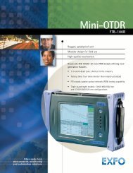
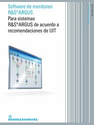
<strong>7461A</strong>/<strong>7451A</strong><br />
<strong>Digital</strong> <strong>Multimeter</strong><br />
High-speed and variable integration time DMM<br />
supporting multiple applications<br />
● Two models by use<br />
6½-digit display (<strong>7461A</strong>)<br />
5½-digit display (<strong>7451A</strong>)<br />
● Fast sampling : 20,000 readings/sec (<strong>7461A</strong>)<br />
5,000 readings/sec (<strong>7451A</strong>)<br />
● Variable integration time: 10µs to 10s (<strong>7461A</strong>), 100µs to 10s (<strong>7451A</strong>)<br />
● High-resolution DCI measurement: 1nA (<strong>7461A</strong>), 10nA (<strong>7451A</strong>)<br />
● Two-channel DCV measurement<br />
● Full array of trigger functions<br />
http://www.adcmt-e.com
New Measurement Stage with Variable Integration Time<br />
6½-digit (<strong>7461A</strong>) and 5½-digit (<strong>7451A</strong>) digital multimeters<br />
Achieve both high performance and low price<br />
The <strong>7461A</strong> and the <strong>7451A</strong> are digital multimeters with<br />
6½-digit and 5½-digit display respectively, providing high<br />
performance with low price.<br />
These multimeters realize high-speed sampling performance<br />
with selective sampling modes by adopting the<br />
newly developed A/D converter, supporting a variety of<br />
applications including digitization of pulse signals, logging<br />
measurement at certain intervals.<br />
As another feature, the integration time can be set to any<br />
values. This enables correctly measuring the average values<br />
of pulsed current/voltage, which cannot be measured<br />
by former models.<br />
In addition to the conventional external trigger functions,<br />
extensive internal trigger functions have been added, allowing<br />
easy capturing of the measured data.<br />
Furthermore, these multimeters are provided with twochannel<br />
DC voltage measurement (Bch 10V range fixed),<br />
so that low cost measurement system architecture is available.<br />
Since both GPIB and USB interfaces are mounted as standard,<br />
it is easy to capture data, extending the support to<br />
automated production lines and other applications.<br />
<br />
<br />
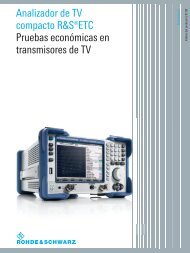
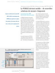
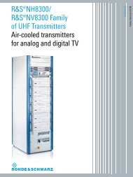
Front Panel<br />
Rear Panel<br />
Eye-friendly vacuum fluorescent display<br />
Twelve measurement functions<br />
Smoothing function<br />
Rear input<br />
USB interface<br />
Five sampling rates<br />
<strong>7461A</strong><br />
Three-layer structure menus<br />
Trigger input<br />
GPIB interface<br />
Comparator output<br />
<strong>7451A</strong><br />
2
Features<br />
■ High Speed Sampling<br />
By adopting the newly developed variable integration time A/D converter,<br />
the <strong>7461A</strong> and the <strong>7451A</strong> realize the highest sampling rate<br />
of 20,000 readings per sec and 5,000 readings per sec with 3½-digit<br />
resolution respectively. The sampling interval can be set from 50µs to<br />
3,600s for the <strong>7461A</strong>, and from 200µs to 3,600s for the <strong>7451A</strong>, which<br />
allows high-speed digitization and data logging at precise measurement<br />
intervals.<br />
■ Full Array of Trigger Functions<br />
Various types of measurements are supported by the built-in trigger<br />
functions such as the level trigger and the delta trigger.<br />
Maximum sampling rate: 200 readings/sec (from 5ms)<br />
<br />
➝<br />
<br />
<br />
<br />
Function <strong>7461A</strong> <strong>7451A</strong><br />
Maximum sampling rate<br />
Memory 20,000 5,000<br />
GPIB 1,000 1,000<br />
Integration time 10µs to 10s 100µs to 10s<br />
Sampling period 50µs to 3,600s 200µs to 3,600s<br />
Maximum display/PLC 6½ digits 5½ digits<br />
Data memory 10,000 10,000<br />
*PLC : Power Line Cycle<br />
<br />
<br />
<br />
■ Variable Integration Time<br />
The integration time can be set from 10µs to 10s for the <strong>7461A</strong> and<br />
from 100µs to 10s for the <strong>7451A</strong>, which allows you to easily measure<br />
the average current of cellular phones or LCDs. The newly developed<br />
A/D converter of which integration time can be set to any values is<br />
based on the analog integration technique, so that it provides precise<br />
average measurement data, differently from the digital method using<br />
a discrete sampling.<br />
<br />
<br />
<br />
➝<br />
<br />
<br />
<br />
<br />
<br />
<br />
<br />
<br />
<br />
<br />
<br />
<br />
■ Low Power Resistance Measurement<br />
In resistance measurement, measurement current may cause heat<br />
generation in a measured device and variation in its measured values.<br />
Low-power 2WΩ/4WΩ resistance measurement uses only 1/10 of the<br />
typical measurement current, minimizing the effect of thermal fluctuation.<br />
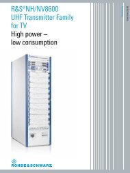
■ Easy System Configuration by Two-channel DCV Measurement<br />
With the DCV-Bch input (10V range<br />
fixed), current measurement and<br />
<br />
<br />
<br />
<br />
<br />
<br />
<br />
two-channel voltage measurement<br />
<br />
<br />
<br />
<br />
<br />
<br />
can be switched, which enhances the<br />
measurement throughput. (Rating<br />
voltage between Bch Hi and COM:<br />
12V)<br />
• CH1 : output current<br />
<br />
<br />
<br />
<br />
<br />
<br />
• CH2 : output voltage<br />
• CH3 : input voltage<br />
<br />
<br />
Bch input voltage range to COM: ±12V<br />
Measurement timing is not parallel.<br />
3
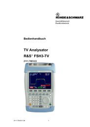
Applications<br />
Standby Current Measurement of Cellular Phone<br />
In a cellular phone, the peak current flows in the standby state at<br />
a constant period, and the base current flows in other states. This<br />
standby time varies depending on the adopted method. To measure<br />
the average current precisely, it is necessary to measure all current<br />
passing during the standby time.<br />
The <strong>7461A</strong> and the <strong>7451A</strong> are capable of current waveform measurement<br />
including peak current measurement by fast sampling of<br />
20,000 readings and 5,000 readings per second respectively. Also,<br />
these models are capable of accurate average current measurement<br />
by using the variable integration time function, in which the integration<br />
time can be set to any value up to 10 seconds.<br />
Current waveform Measurement and Average Current Measurement<br />
<br />
<br />
<br />
<br />
<br />
<br />
<br />
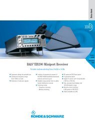
Rising Signal Measurement by Delta Trigger and Pre-Trigger<br />
The delta trigger starts measurement by detecting the slope of a signal.<br />
This function is convenient for starting measurement when data<br />
increases or is stabilized after convergence, and also supports various<br />
kinds of change patterns.<br />
The pre-trigger is used to capture data before the trigger event. This<br />
function is convenient for analyzing signal states, for example, when<br />
an abnormal measurement value is detected.<br />
<br />
<br />
<br />
<br />
<br />
<br />
<br />
<br />
<br />
<br />
<br />
<br />
<br />
<br />
<br />
<br />
<br />
<br />
<br />
<br />
<br />
<br />
<br />
Delta trigger setting example<br />
Measurement starts when the signal change exceeds +0.2A.<br />
Thermistor Low-Power Resistance Measurement<br />
The <strong>7461A</strong>/<strong>7451A</strong> is equipped with the low-power resistance measurement<br />
function as standard. This enables measurement of a<br />
thermistor or other heat sensitive elements with reduced effect from<br />
self-heating.<br />
When a thermistor is measured in the 1kΩ range with the normal<br />
4WΩ function, the measurement current is 1mA and the resistance<br />
values will change significantly.<br />
On the other hand, the LP4WΩ function is used, the measurement<br />
current is 100µA which is 1/10 the normal value 4WΩ, and there<br />
will be small change in resistance values.<br />
Ω<br />
<br />
<br />
<br />
<br />
<br />
Ω<br />
<br />
<br />
<br />
Ω<br />
<br />
<br />
<br />
<br />
4
Low-Noise Current Measurement (<strong>7461A</strong>)<br />
The <strong>7461A</strong> is stable in low current measurement and also highly sensitive<br />
with the minimum resolution of 1nA. Its performance is quite<br />
useful for evaluation and inspection of portable devices and electronic<br />
components that require low current consumption.<br />
DCI 10mA-Range Measurement Variation Comparison in 1PLC<br />
<strong>7461A</strong> 4 digits (40nA) A Company 6½-digit DMM 26 digits (260nA)<br />
<br />
<br />
<br />
<br />
<br />
<br />
<br />
<br />
<br />
<br />
<br />
<br />
<br />
<br />
<br />
<br />
<br />
<br />
<br />
<br />
<br />
<br />
<br />
<br />
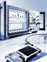
USB Interface as Standard<br />
This instrument is equipped with a USB interface in addition to a<br />
GPIB interface as standard, allowing easy measurement data transfer<br />
to a PC. The following shows an example of controlling the digital<br />
multimeter and capturing measurement data onto an Excel sheet in<br />
graphical format by using sample software. In this way, automatic<br />
measurement is easily achieved by connecting through the USB interface.<br />
Measurement example (Excel window)<br />
<br />
1 DCV_<br />
+052.1439E-03<br />
<br />
2 DCV_ +052.1531E-03<br />
3 DCV_<br />
+052.1679E-03<br />
: <br />
ENTER × n<br />
4 DCV_ +052.1701E-03<br />
5 DCV_ +052.1888E-03<br />
6 DCV_ +052.1937E-03<br />
STOP<br />
7 DCV_ +052.2012E-03<br />
8 DCV_ +052.1988E-03<br />
9 DCV_ +052.1855E-03<br />
10<br />
DCV_ +052.1749E-03<br />
11<br />
DCV_ +052.1663E-03<br />
Attach to any sample sheet from the<br />
measurement sample software.<br />
<br />
<br />
<br />
<br />
<br />
<br />
<br />
<br />
<br />
<br />
<br />
<br />
<br />
<br />
<br />
<br />
<br />
5
Specifications Unless otherwise specified, the measurement accuracy is guaranteed for one year under the following conditions: Temperature; 23±5°C, relative<br />
humidity; 85% or less (75% or less in resistance measurement of 20MΩ or more and low power resistance measurement of 2MΩ or more).<br />
Temperature coefficient: For the 4 ½-digit display, the digit error is reduced to 1/10.<br />
■ DC Voltage Measurement (DCV)<br />
<strong>7461A</strong><br />
Measurement accuracy *1<br />
Temperature coefficient<br />
Input<br />
Maximum<br />
Input<br />
Range<br />
Resolution<br />
± (% of reading + digits)<br />
± (ppm of reading + digits)/˚C<br />
terminal<br />
display<br />
impedance *3 24 hours: 23˚C±1˚C *2 90 days: 23˚C±5˚C 1 year: 23˚C±5˚C Auto-zero ON Auto-zero OFF<br />
V−COM 100mV 119.9999 100nV More than 1GΩ/10MΩ±1% 0.0030+30.0 0.0040+35.0 0.0040+35.0 5.0+5.0 5.0+7.0<br />
1000mV 1199.999 1µV More than 1GΩ/10MΩ±1% 0.0020+4.0 0.0030+5.0 0.0040+5.0 5.0+1.0 5.0+5.0<br />
10V 11.99999 10µV More than 1GΩ/10MΩ±1% 0.0020+3.0 0.0030+3.0 0.0035+3.0 5.0+1.0 5.0+5.0<br />
100V 119.9999 100µV 10MΩ±1% 0.0020+5.0 0.0035+5.0 0.0045+5.0 5.0+1.0 5.0+5.0<br />
1000V 1099.999 1mV 10MΩ±1% 0.0020+5.0 0.0035+5.0 0.0040+5.0 5.0+1.0 5.0+5.0<br />
BchHi−COM 10V 11.99999 10µV More than 1GΩ 0.0020+3.0 0.0030+3.0 0.0035+3.0 5.0+1.0 5.0+5.0<br />
*1 Integration time: 10 PLC, Display digit: 6½, Auto-zero: ON<br />
*2 Relative to the calibration accuracy<br />
*3 In the 100mV, 1000mV, and 10V ranges, the input impedance can be selected from either 10MΩ or more than 1GΩ<br />
<strong>7451A</strong><br />
Measurement accuracy *1<br />
Temperature coefficient<br />
Input<br />
Maximum<br />
Input<br />
Range<br />
Resolution<br />
± (% of reading + digits)<br />
± (ppm of reading + digits)/˚C<br />
terminal<br />
display<br />
impedance *3 24 hours: 23˚C±1˚C *2 90 days: 23˚C±5˚C 1 year: 23˚C±5˚C Auto-zero ON Auto-zero OFF<br />
V−COM 300mV 319.999 1µV More than 1GΩ/10MΩ±1% 0.0020+5.0 0.0060+7.0 0.0140+7.0 8.0+1.0 8.0+5.0<br />
3000mV 3199.99 10µV More than 1GΩ/10MΩ±1% 0.0020+2.0 0.0060+3.0 0.0100+3.0 7.0+0.1 7.0+3.0<br />
30V 31.9999 100µV 10MΩ±1% 0.0020+3.0 0.0070+6.0 0.0150+6.0 8.0+1.0 8.0+3.0<br />
300V 319.999 1mV 10MΩ±1% 0.0020+2.0 0.0060+3.0 0.0140+3.0 8.0+0.1 8.0+3.0<br />
1000V 1099.99 10mV 10MΩ±1% 0.0020+2.0 0.0060+3.0 0.0140+3.0 8.0+0.1 8.0+1.2<br />
BchHi−COM 10V 11.9999 100µV More than 1GΩ 0.0020+2.0 0.0100+3.0 0.0100+3.0 8.0+0.1 8.0+1.0<br />
*1 Integration time: 10 PLC, Display digit: 6½, Auto-zero: ON<br />
*2 Relative to the calibration accuracy<br />
*3 In the 300mV and 3000mV ranges, the input impedance can be selected from either 10MΩ or more than 1GΩ<br />
<strong>7461A</strong>/<strong>7451A</strong><br />
Additional error depending on the integration time<br />
Integration time<br />
Additional error ± (digits + µV)<br />
<strong>7461A</strong><br />
<strong>7451A</strong><br />
10µs ≤ IT ≤ 200µs — 3½ digits: 2+20 —<br />
100µs ≤ IT ≤ 200µs — — 3½digits: 2+20<br />
200µs < IT ≤ 2ms Includes FAST1 and FAST2 4½ digits: 2+20 4½digits: 10+20<br />
2 ms < IT < 1 PLC — 5½ digits: 2+20 —<br />
2.01ms ≤ IT≤ 9.99ms — — 5½digits: 20+20<br />
10 ms ≤ IT < 1 PLC — — 5½digits: 2+20<br />
1PLC≤ IT < 10PLC Integral multiple of 1PLC 6½ digits: 1+0 5½digits: 1+0<br />
10PLC < IT ≤ 10s Integral multiple of 1PLC 6½ digits: 2+0 5½digits: 2+0<br />
Maximum input<br />
Between V and COM<br />
Between BchHi and COM<br />
Noise rejection ratio<br />
1000 Vpeak<br />
200 Vpeak<br />
Integration<br />
Effective CMRR *4<br />
NMRR<br />
time<br />
DC 50/60Hz ±0.08% 50/60Hz ±0.08%<br />
Integral multiple of 1PLC 130dB 120dB 60dB<br />
Others 130dB 60dB 0dB<br />
*4 Unbalanced impedance of 1kΩ<br />
■ AC Voltage Measurement (ACV, ACV (AC+DC))<br />
<strong>7461A</strong><br />
Measurement method: True RMS measurement, RMS display<br />
Input range: 5% or more of a full scale<br />
Crest factor : 5 : 1 at a full scale<br />
Temperature coefficient: (1/10 of measurement accuracy that includes the additional error)/˚C in each range and frequency range)<br />
ACV<br />
Input<br />
terminal<br />
Range<br />
Maximum<br />
display<br />
Resolution<br />
Input<br />
impedance<br />
Measurement accuracy *1 ± (% of reading + digits) 23˚C±5˚C<br />
20Hz−45Hz 45Hz−100Hz 100Hz−20kHz 20kHz−50kHz 50kHz−100kHz 100kHz−300kHz *2<br />
V−COM 100mV 119.9999 100nV 1MΩ±2%, 140pF or less 0.28+600 0.1+600 0.06+600 0.12+1800 0.6+2100 5+6000<br />
1000mV 1199.999 1µV 1MΩ±2%, 140pF or less 0.28+500 0.1+500 0.06+500 0.12+500 0.6+800 4+5000<br />
10V 11.99999 10µV 1MΩ±2%, 140pF or less 0.28+400 0.1+400 0.06+400 0.12+500 0.6+800 4+5000<br />
100V 119.9999 100µV 1MΩ±2%, 140pF or less 0.28+400 0.1+400 0.06+400 0.12+500 0.6+800 4+5000<br />
700V 749.999 1mV 1MΩ±2%, 140pF or less 0.28+280 0.1+280 0.06+280 0.12+350 0.6+580 4+3500<br />
*1 AC filter : SLOW, Integration time: 10PLC, Display digit: 6½, Sine-wave input. The input voltage is restricted to 2.2 x 10 7 V Hz in the 100V and 700V ranges.<br />
If the input voltage is 10% or less of the full scale, 30µV is added to the measurement accuracy as the additional error.<br />
*2 100kHz-200kHz in the 100mV and 1000mV range.<br />
ACV (AC+DC)<br />
Input<br />
terminal<br />
Range<br />
Maximum<br />
display<br />
Resolution<br />
Input<br />
impedance<br />
Measurement accuracy *1 ± (% of reading + digits) 23˚C±5˚C<br />
20Hz−45Hz 45Hz−100Hz 100Hz−20kHz 20kHz−50kHz 50kHz−100kHz 100kHz−300kHz *2<br />
V−COM 100mV 119.99 10µV 1MΩ±12%, 140pF or less 0.28+6 0.1+6 0.06+6 0.12+18 0.6+21 5+60<br />
1000mV 1199.9 100µV 1MΩ±12%, 140pF or less 0.28+5 0.1+5 0.06+5 0.12+5 0.6+8 4+50<br />
10V 11.999 1mV 1MΩ±12%, 140pF or less 0.28+4 0.1+4 0.06+4 0.12+5 0.6+8 4+50<br />
100V 119.99 10mV 1MΩ±12%, 140pF or less 0.28+4 0.1+4 0.06+4 0.12+5 0.6+8 4+50<br />
700V 749.9 100mV 1MΩ±12%, 140pF or less 0.28+3 0.1+3 0.06+3 0.12+4 0.6+6 4+35<br />
*1 AC filter: SLOW, Integration time: 10PLC, Display digit: 4½, Sine-wave input. The input voltage is restricted to 2.2 x 10 7 V Hz in the 100V and 700V ranges.<br />
If the input voltage is 10% or less of the full scale, 30µV is added to the measurement accuracy as the additional error.<br />
*2 100kHz-200kHz in the 100mV and 1000mV range.<br />
6
<strong>7451A</strong><br />
Measurement method: True RMS measurement, RMS display<br />
Input range: 5% or more of a full scale<br />
Crest factor: 3 : 1 at a full scale<br />
Temperature coefficient: (1/10 of measurement accuracy that includes the additional error)/ ˚C in each range and frequency range)<br />
ACV<br />
Input<br />
terminal<br />
Range<br />
Maximum<br />
display<br />
Resolution<br />
Input<br />
impedance<br />
Measurement accuracy *1 ± (% of reading + digits)<br />
20Hz−45Hz 45Hz−100Hz 100Hz−20kHz 20kHz−50kHz 50kHz−100kHz 100kHz−300kHz *2<br />
V−COM 300mV 319.999 1µV 1MΩ±2%, 140pF or less 0.28+120 0.1+120 0.06+120 0.2+150 0.6+240 5+1500<br />
3000mV 3199.99 10µV 1MΩ±2%, 140pF or less 0.28+120 0.1+120 0.06+120 0.2+150 0.6+240 4+1500<br />
30V 31.9999 100µV 1MΩ±2%, 140pF or less 0.28+120 0.1+120 0.06+120 0.2+150 0.6+240 4+1500<br />
300V 319.999 1mV 1MΩ±2%, 140pF or less 0.28+120 0.1+120 0.06+120 0.2+150 0.6+240 4+1500<br />
700V 749.99 10mV 1MΩ±2%, 140pF or less 0.28+28 0.1+28 0.06+28 — — —<br />
*1 AC filter: SLOW, Integration time: 10PLC, Display digit: 5½, Sine-wave input. The input voltage is restricted to 2.2 x 10 7 V Hz in the 300V and 700V ranges.<br />
*2 100kHz-200kHz in the 300mV and 3000mV range.<br />
ACV (AC+DC)<br />
Input<br />
terminal<br />
Range<br />
Maximum<br />
display<br />
Resolution<br />
Input<br />
impedance<br />
Measurement accuracy *1 ± (% of reading + digits)<br />
20Hz−45Hz 45Hz−100Hz 100Hz−20kHz 20kHz−50kHz 50kHz−100kHz 100kHz−300kHz *2<br />
V−COM 300mV 319.99 10µV 1MΩ±12%, 140pF or less 0.28+12 0.1+12 0.06+12 0.2+15 0.6+24 4+150<br />
3000mV 3199.9 100µV 1MΩ±12%, 140pF or less 0.28+12 0.1+12 0.06+12 0.2+15 0.6+24 4+150<br />
30V 31.999 1mV 1MΩ±12%, 140pF or less 0.28+12 0.1+12 0.06+12 0.2+15 0.6+24 4+150<br />
300V 319.99 10mV 1MΩ±12%, 140pF or less 0.28+12 0.1+12 0.06+12 0.2+15 0.6+24 4+150<br />
700V 749.9 100mV 1MΩ±12%, 140pF or less 0.28+3 0.1+3 0.06+3 — — —<br />
*1 AC filter: SLOW, Integration time: 10PLC, Display digit: 4½, Sine-wave input. The input voltage is restricted to 2.2 x 10 7 V Hz in the 300V and 700V ranges.<br />
*2 100kHz-200kHz in the 300mV and 3000mV range.<br />
<strong>7461A</strong>/<strong>7451A</strong><br />
Additional error depending on the crest factor<br />
(For non-sine-wave input)<br />
<strong>7461A</strong><br />
<strong>7451A</strong><br />
1−2 0.05% of range 0.05% of range<br />
2−3 0.15% of range 0.15% of range<br />
3−5 0.4% of range —<br />
Additional error depending on the AC filter Integration time: 10PLC<br />
Frequency bandwidth<br />
Additional error (% of reading)<br />
20Hz−45Hz 45Hz−100Hz 100Hz−1kHz More than 1kHz<br />
Response time *1<br />
SLOW 20Hz−300kHz 0 0 0 0 3s<br />
MED 20Hz−300kHz 0.7 0.23 0.04 0 500ms<br />
FAST 300Hz−300kHz — — 0.1 0 100ms<br />
*1 Time until the measurement value reaches within 0.1% of the final value in the same range.<br />
Additional error depending on the integration time<br />
AC filter: SLOW<br />
Integration time<br />
Additional error (±digits)<br />
<strong>7461A</strong><br />
<strong>7451A</strong><br />
10µs ≤ IT < 200µs — 3½ digits: 2 —<br />
100µs ≤ IT < 200µs — — 3½ digits: 2<br />
200µs ≤ IT ≤ 2ms Includes FAST1 and FAST2 4½ digits: 4 4½ digits: 10<br />
2ms < IT < 1PLC — 5½ digits: 20 —<br />
2.01ms ≤ IT ≤ 9.99ms — — 5½ digits: 20<br />
10ms ≤ IT < 1PLC — — 5½ digits: 12<br />
1PLC ≤ IT < 10PLC — 6½ digits: 120 5½ digits: 10<br />
10PLC < IT ≤ 10s — 6½ digits: 2 5½ digits: 2<br />
Maximum input<br />
Between V and COM<br />
700Vrms, 1000Vpeak, 2.2 × 10 7 VHz<br />
■ Resistance Measurement (2WΩ, LP-2WΩ, 4WΩ, LP-4WΩ)<br />
<strong>7461A</strong><br />
2WΩ/4WΩ measurement<br />
Range<br />
Maximum<br />
display<br />
Resolution<br />
Measurement<br />
current<br />
Measurement accuracy *1<br />
± (% of reading + digits)<br />
Temperature coefficient *4<br />
± (ppm of reading + digits)/˚C<br />
24 hours: 23˚C±1˚C *2 90 days: 23˚C±5˚C 1 year: 23˚C±5˚C Auto-zero ON Auto-zero OFF<br />
100Ω 119.9999 100µΩ 10mA 0.0030+30.0 0.0060+35.0 0.0080+35.0 6.0+5.0 6.0+5.0<br />
1000Ω 1199.999 1mΩ 1mA 0.0020+5.0 0.0060+5.0 0.0080+8.0 6.0+1.0 6.0+5.0<br />
10kΩ 11.99999 10mΩ 100µA 0.0020+5.0 0.0060+5.0 0.0080+8.0 6.0+1.0 6.0+5.0<br />
100kΩ 119.9999 100mΩ 10µA 0.0020+5.0 0.0060+5.0 0.0080+8.0 6.0+1.0 6.0+5.0<br />
1000kΩ 1199.999 1Ω 5µA 0.0020+10.0 0.0060+30.0 0.0080+30.0 10.0+5.0 10.0+7.0<br />
10MΩ 11.99999 10Ω 500nA 0.0150+10.0 0.0200+30.0 0.0300+30.0 30.0+5.0 *3 30.0+7.0 *3<br />
100MΩ 119.9999 100Ω 50nA 0.3000+100.0 0.5000+100.0 0.6000+100.0 700.0+5.0 700.0+7.0<br />
*1 Integration time: 10 PLC, Auto-zero: ON for 2WΩ, Display digit: 6½<br />
The offset error, which consists of the input cable resistance and 0.2Ω, is added in 2WΩ measurement.<br />
*2 Relative to the calibration standard<br />
Low power 2WΩ/4WΩ measurement (LP-2WΩ/LP-4WΩ)<br />
Range<br />
Maximum<br />
display<br />
Resolution<br />
Measurement<br />
current<br />
*3 15ppm/˚C is added in the temperature range of 30˚C to 50˚C.<br />
*4 The temperature coefficient in Auto-zero ON is used in the 4WΩ measurement.<br />
Measurement accuracy *1<br />
± (% of reading + digits)<br />
Temperature coefficient *4<br />
± (ppm of reading + digits)/˚C<br />
24 hours: 23˚C±1˚C *2 90 days: 23˚C±5˚C 1 year: 23˚C±5˚C Auto-zero ON Auto-zero OFF<br />
100Ω 119.9999 100µΩ 1mA 0.0030+30.0 0.0070+50.0 0.0100+60.0 6.0+5.0 6.0+8.0<br />
1000Ω 1199.999 1mΩ 100µA 0.0020+30.0 0.0070+50.0 0.0100+60.0 6.0+5.0 6.0+8.0<br />
10kΩ 11.99999 10mΩ 10µA 0.0020+30.0 0.0070+50.0 0.0100+60.0 7.0+5.0 7.0+8.0<br />
100kΩ 119.9999 100mΩ 5µA 0.0020+15.0 0.0070+50.0 0.0100+60.0 10.0+5.0 10.0+25.0<br />
1000kΩ 1199.999 1Ω 500nA 0.0150+15.0 0.0450+50.0 0.0500+60.0 65.0+5.0 *3 65.0+8.0 *3<br />
0.8000+100.0 700.0+5.0 700.0+8.0 *3<br />
*1 Integration time: 10 PLC, Auto-zero: ON for 2WΩ, Display digit: 6½<br />
*3 15ppm/˚C is added in the temperature range of 30˚C to 50˚C.<br />
The offset error, which consists of the input cable resistance and 0.2Ω, is added in 2WΩ measurement. *4 The temperature coefficient in Auto-zero ON is used in the 4WΩ measurement.<br />
*2 Relative to the calibration standard<br />
Response time: 100MΩ=5s (Time until the measurement value reaches within 0.1% of the final value)<br />
1MΩ/10MΩ=0.5s (Time until the measurement value reaches within 0.1% of the final value)<br />
10MΩ 11.99999 10Ω 50nA 0.3000+100.0 0.6000+100.0<br />
7
<strong>7451A</strong><br />
2WΩ/4WΩ measurement<br />
Range<br />
Maximum<br />
display<br />
Resolution<br />
Measurement<br />
current<br />
Measurement accuracy *1<br />
± (% of reading + digits)<br />
Temperature coefficient *5<br />
± (ppm of reading + digits)/˚C<br />
24 hours: 23˚C±1˚C *2 90 days: 23˚C±5˚C 1 year: 23˚C±5˚C Auto-zero ON Auto-zero OFF<br />
30Ω 31.9999 100µΩ 10mA 0.0030+30.0 0.0100+40.0 0.0150+40.0 10.0+5.0 10.0+50.0<br />
300Ω 319.999 1mΩ 1mA 0.0020+5.0 0.0080+11.0 0.0150+11.0 10.0+1.0 10.0+6.0<br />
3000Ω 3199.99 10mΩ 1mA 0.0020+3.0 0.0070+3.0 0.0120+3.0 10.0+0.2 10.0+3.0<br />
30kΩ 31.9999 100mΩ 100µA 0.0020+3.0 0.0070+3.0 0.0130+3.0 10.0+0.2 10.0+3.0<br />
300kΩ 319.999 1Ω 10µA 0.0020+3.0 0.0090+3.0 0.0140+3.0 8.0+0.2 8.0+3.0<br />
3000kΩ 3199.99 10Ω 1µA 0.0070+14.0 0.0300+19.0 0.0300+19.0 35.0+5.0 35.0+5.0<br />
30MΩ 31.9999 100Ω 100nA 0.0600+14.0 0.1800+19.0 0.2000+19.0 100.0+5.0 *3 100.0+5.0 *3<br />
300MΩ 319.999 1kΩ 10nA 0.6000+14.0 1.7000+19.0 2.0000+19.0 1000.0+5.0 *4 1000.0+5.0 *4<br />
*1 Integration time: 10 PLC, Auto-zero: ON for 2WΩ, Display digit: 5½<br />
The offset error, which consists of the input cable resistance and 0.2Ω, is added in 2WΩ measurement.<br />
*2 Relative to the calibration standard<br />
*3 115ppm/˚C is added in the temperature range of 30˚C to 50˚C.<br />
*4 1150ppm/˚C is added in the temperature range of 30˚C to 50˚C.<br />
*5 The temperature coefficient in Auto-zero ON is used in the 4WΩ measurement.<br />
Low power 2WΩ/4WΩ measurement (LP-2WΩ/LP-4WΩ)<br />
Range<br />
Maximum<br />
display<br />
Resolution<br />
Measurement<br />
current<br />
Measurement accuracy *1<br />
± (% of reading + digits)<br />
Temperature coefficient *5<br />
± (ppm of reading + digits)/˚C<br />
24 hours: 23˚C±1˚C *2 90 days: 23˚C±5˚C 1 year: 23˚C±5˚C Auto-zero ON Auto-zero OFF<br />
300Ω 319.999 1mΩ 100µA 0.0030+30.0 0.0080+40.0 0.0150+40.0 10.0+5.0 10.0+50.0<br />
3000Ω 3199.99 10mΩ 100µA 0.0020+5.0 0.0080+11.0 0.0150+11.0 10.0+1.0 10.0+5.0<br />
30kΩ 31.9999 100mΩ 10µA 0.0020+5.0 0.0080+11.0 0.0150+11.0 10.0+1.0 10.0+5.0<br />
300kΩ 319.999 1Ω 1µA 0.0070+5.0 0.0300+11.0 0.0300+11.0 30.0+1.0 30.0+5.0<br />
3000kΩ 3199.99 10Ω 100nA 0.0600+20.0 0.1800+33.0 0.2000+33.0 100.0+5.0 *3 100.0+5.0 *3<br />
30MΩ 31.9999 100Ω 10nA 0.6000+20.0 1.7000+33.0 2.0000+33.0 1000.0+5.0 *4 1000.0+5.0 *4<br />
*1 Integration time: 10 PLC, Auto-zero: ON for 2WΩ, Display digit: 5½<br />
The offset error, which consists of the input cable resistance and 0.2Ω, is added in 2WΩ measurement.<br />
*2 Relative to the calibration standard<br />
*3 115ppm/˚C is added in the temperature range of 30˚C to 50˚C.<br />
*4 1150ppm/˚C is added in the temperature range of 30˚C to 50˚C.<br />
*5 The temperature coefficient in Auto-zero ON is used in the 4WΩ measurement.<br />
Response time: 300MΩ=5s (Time until the measurement value reaches within 0.1% of the final value)<br />
3MΩ/30MΩ=0.5s (Time until the measurement value reaches within 0.1% of the final value)<br />
<strong>7461A</strong>/<strong>7451A</strong><br />
Additional error depending on the integration time<br />
Integration time<br />
Additional error ± (digits + mΩ)<br />
<strong>7461A</strong><br />
<strong>7451A</strong><br />
10µs ≤ IT ≤ 200µs — 3½ digits: 2+20 —<br />
100µs ≤ IT ≤ 200µs — — 3½ digits: 2+20<br />
200µs < IT ≤ 2ms Includes FAST1 and FAST2 4½ digits: 2+20 4½ digits: 10+20<br />
2ms < IT < 1PLC — 5½ digits: 2+20 —<br />
2.01ms ≤ IT ≤ 9.99ms — — 5½ digits: 20+20<br />
10ms ≤ IT < 1PLC — — 5½ digits: 2+20<br />
1PLC ≤ IT < 10PLC Integral multiple of 1PLC 6½ digits: 1+0 5½ digits: 1+0<br />
10PLC < IT ≤ 10s Integral multiple of 1PLC 6½ digits: 2+0 5½ digits: 2+0<br />
Open-circuit voltage: 9.5V or less<br />
Maximum input<br />
Between Ω and COM<br />
Between 4WΩHi and 4WΩLo<br />
1000Vpeak<br />
200Vpeak<br />
■ DC Current Measurement (DCI)<br />
<strong>7461A</strong><br />
Input<br />
terminal<br />
Range<br />
Maximum<br />
display<br />
Resolution<br />
Resistance<br />
between input<br />
terminals<br />
Measurement accuracy *1<br />
± (% of reading + digits)<br />
Temperature coefficient<br />
± (ppm of reading + digits)/˚C<br />
24 hours: 23˚C±1˚C *2 90 days: 23˚C±5˚C 1 year: 23˚C±5˚C Auto-zero ON Auto-zero OFF<br />
mA−COM 1000µA 1199.999 1nA 103Ω 0.005+15 0.0180+20.0 0.0200+20.0 30.0+5.0 30.0+6.0<br />
10mA 11.99999 10nA 10.5Ω 0.005+15 0.0250+20.0 0.0250+30.0 30.0+5.0 30.0+6.0<br />
100mA 119.9999 100nA 1.5Ω 0.008+15 0.0250+20.0 0.0250+30.0 35.0+5.0 35.0+6.0<br />
1000mA 1199.999 1µA 0.5Ω 0.03+15 0.0300+20.0 0.0500+30.0 50.0+10.0 50.0+10.0<br />
3A 3.19999 10µA 0.5Ω 0.1+15 0.1000+20.0 0.1000+30.0 50.0+20.0 50.0+30.0<br />
*1 Integration time: 10 PLC, Display digit: 6½, Auto-zero: ON<br />
*2 Relative to the calibration standard<br />
<strong>7451A</strong><br />
Input<br />
terminal<br />
Range<br />
Maximum<br />
display<br />
Resolution<br />
Resistance<br />
between input<br />
terminals<br />
Measurement accuracy *1<br />
± (% of reading + digits)<br />
Temperature coefficient<br />
± (ppm of reading + digits)/˚C<br />
24 hours: 23˚C±1˚C *2 90 days: 23˚C±5˚C 1 year: 23˚C±5˚C Auto-zero ON Auto-zero OFF<br />
mA−COM 3000µA 3199.99 10nA 10.5Ω 0.01+30 0.0300+40.0 0.0500+40.0 45.0+4.0 45.0+10.0<br />
30mA 31.9999 100nA 10.5Ω 0.01+4.5 0.0300+6.0 0.0500+6.0 45.0+0.6 45.0+7.0<br />
300mA 319.999 1µA 1.5Ω 0.03+4.5 0.0600+6.0 0.1000+6.0 50.0+0.6 50.0+7.0<br />
3000mA 3199.99 10µA 0.5Ω 0.12+4.5 0.1200+6.0 0.1200+6.0 50.0+0.6 50.0+7.0<br />
*1 Integration time: 10 PLC, Display digit: 5½, Auto-zero: ON<br />
*2 Relative to the calibration standard<br />
8
<strong>7461A</strong>/<strong>7451A</strong><br />
Additional error depending on the integration time<br />
Integration time<br />
Additional error (±digits)<br />
<strong>7461A</strong><br />
<strong>7451A</strong><br />
10µs ≤ IT ≤ 200µs — 3½ digits: 2 —<br />
100µs ≤ IT ≤ 200µs — — 3½ digits: 2<br />
200µs < IT ≤ 2ms Includes FAST1 and FAST2 4½ digits: 2 4½ digits: 10<br />
2ms < IT < 1PLC — 5½ digits: 2 —<br />
2.01ms ≤ IT ≤ 9.99ms — — 5½ digits: 20<br />
10ms ≤ IT < 1PLC — — 5½ digits: 2<br />
1PLC ≤ IT < 10PLC Integral multiple of 1PLC 6½ digits: 1 5½ digits: 1<br />
10PLC < IT ≤ 10s Integral multiple of 1PLC 6½ digits: 2 5½ digits: 2<br />
Maximum allowable applied current<br />
Between mA and COM : 3A (DC or ACrms)<br />
Input protection : By using the 3.15A/250V fast blow fuse<br />
which is compliant with IEC127 sheet1<br />
The fuse can be changed on the rear panel.<br />
■ AC Current Measurement (ACI, ACI (AC+DC))<br />
<strong>7461A</strong><br />
Measurement method: True RMS measurement, RMS display<br />
Input range: 5% or more of a full scale<br />
Crest factor: 5 : 1 at a full scale (except for the 3A range)<br />
Temperature coefficient: (1/10 of measurement accuracy that includes the additional error)/ ˚C in each range and frequency range)<br />
ACI<br />
Input<br />
terminal<br />
Range<br />
Maximum<br />
display<br />
Resolution<br />
Resistance<br />
between input<br />
terminals<br />
Measurement accuracy *1<br />
± (% of reading + digits) 23˚C±5˚C<br />
20Hz−45Hz 45Hz−100Hz 100Hz−5kHz<br />
mA−COM 1000µA 1199.999 1nA 103Ω 0.45+400 0.25+400 0.11+400<br />
10mA 11.99999 10nA 10.5Ω 0.45+400 0.25+400 0.11+400<br />
100mA 119.9999 100nA 1.5Ω 0.45+400 0.25+400 0.11+400<br />
1000mA 1199.999 1µA 0.5Ω 0.45+400 0.25+400 0.11+400<br />
3A 3.19999 10µA 0.5Ω 0.45+120 0.25+120 0.15+120<br />
*1 AC filter: SLOW, Integration time: 10PLC, Display digit: 6½, Sine-wave input<br />
ACI (AC+DC)<br />
Input<br />
terminal<br />
Range<br />
Maximum<br />
display<br />
Resolution<br />
Resistance<br />
between input<br />
terminals<br />
Measurement accuracy *1<br />
± (% of reading + digits) 23˚C±5˚C<br />
20Hz−45Hz 45Hz−100Hz 100Hz−5kHz<br />
mA−COM 1000µA 1199.9 100nA 103Ω 0.45+4 0.25+4 0.11+4<br />
10mA 11.999 1µA 10.5Ω 0.45+4 0.25+4 0.11+4<br />
100mA 119.99 10µA 1.5Ω 0.45+4 0.25+4 0.11+4<br />
1000mA 1199.9 100µA 0.5Ω 0.45+4 0.25+4 0.11+4<br />
3A 3.199 1mA 0.5Ω 0.45+1.2 0.25+1.2 0.15+1.2<br />
*1 AC filter: SLOW, Integration time: 10PLC, Display digit: 4½, Sine-wave input<br />
Additional error depending on the crest factor (For non-sine-wave input)<br />
<strong>7451A</strong><br />
Measurement method: True RMS measurement, RMS display<br />
Input range: 5% or more of a full scale<br />
Crest factor: 3 : 1 at a full scale (except for the 3A range)<br />
Temperature coefficient: (1/10 of measurement accuracy that includes the additional error)/ ˚C in each range and frequency range)<br />
ACI<br />
1−2<br />
2−3<br />
3−5<br />
Input<br />
terminal<br />
Range<br />
Maximum<br />
display<br />
Resolution<br />
Resistance<br />
between input<br />
terminals<br />
Measurement accuracy *1<br />
± (% of reading + digits) 23˚C±5˚C<br />
20Hz−45Hz 45Hz−100Hz 100Hz−5kHz<br />
mA−COM 3000µA 3199.99 10nA 10.5Ω 0.45+200 0.25+200 0.2+200<br />
30mA 31.9999 100nA 10.5Ω 0.45+200 0.25+200 0.2+200<br />
300mA 319.999 1µA 1.5Ω 0.45+200 0.25+200 0.2+200<br />
3000mA 3199.99 10µA 0.5Ω 0.45+200 0.25+200 0.2+200<br />
Input<br />
terminal<br />
Range<br />
0.05% of range<br />
0.15% of range<br />
0.4% of range<br />
*1 AC filter: SLOW, Integration time: 10PLC, Display digit: 5½, Sine-wave input<br />
ACI (AC+DC)<br />
Maximum<br />
display<br />
Resolution<br />
Resistance<br />
between input<br />
terminals<br />
Measurement accuracy *1<br />
± (% of reading + digits) 23˚C±5˚C<br />
20Hz−45Hz 45Hz−100Hz 100Hz−5kHz<br />
mA−COM 3000µA 3199.9 100nA 10.5Ω 0.45+20 0.25+20 0.2+20<br />
30mA 31.999 1µA 10.5Ω 0.45+20 0.25+20 0.2+20<br />
300mA 319.99 10µA 1.5Ω 0.45+20 0.25+20 0.2+20<br />
3000mA 3199.9 100µA 0.5Ω 0.45+20 0.25+20 0.2+20<br />
*1 AC filter: SLOW, Integration time: 10PLC, Display digit: 4½, Sine-wave input<br />
Additional error depending on the crest factor (For non-sine-wave input)<br />
Range<br />
Crest factor ± (% of reading + % of range)<br />
1 to 2 2 to 3<br />
3000µA 0+0.05 0+0.15<br />
30mA 0.01+0.05 3+0.15<br />
300mA 0+0.05 0.3+0.15<br />
3000mA 0+0.05 0.03+0.15<br />
9
<strong>7461A</strong>/<strong>7451A</strong><br />
Additional error depending on the AC filter Integration time: 10PLC<br />
Frequency<br />
Additional error (% of reading)<br />
bandwidth 20Hz−45Hz 45Hz−100Hz 100Hz−1kHz More than 1kHz<br />
Response time *1<br />
SLOW 20Hz−5kHz 0 0 0 0 3s<br />
MED 20Hz−5kHz 0.7 0.23 0.04 0 500ms<br />
FAST 300Hz−5kHz — — 0.1 0 100ms<br />
*1 Time until the measurement value reaches within 0.1% of the final value in the same range.<br />
Maximum allowable applied current<br />
Between mA and COM : 3A (DC or ACrms)<br />
Input protection : By using the 3.15A/250V fast blow fuse which is compliant with IEC127 sheet1<br />
The fuse can be changed on the rear panel.<br />
Additional error depending on the integration time AC filter: SLOW<br />
Integration time<br />
Additional error (±digits)<br />
<strong>7461A</strong><br />
<strong>7451A</strong><br />
10µs ≤ IT < 200µs — 3½ digits: 2 —<br />
100µs ≤ IT < 200µs — — 3½ digits: 2<br />
200µs ≤ IT ≤ 2ms Includes FAST1 and FAST2 4½ digits: 4 4½ digits: 10<br />
2ms < IT < 1PLC — 5½ digits: 20 —<br />
2.01ms ≤ IT ≤ 9.99ms — — 5½ digits: 20<br />
10ms ≤ IT ≤ 1PLC — — 5½ digits: 20<br />
1PLC ≤ IT < 10PLC — 6½ digits: 120 5½ digits: 20<br />
10PLC < IT ≤ 10s — 6½ digits: 2 5½ digits: 2<br />
■ Frequency Measurement (FREQ)<br />
<strong>7461A</strong>/<strong>7451A</strong><br />
Measurement method : Reciprocal<br />
Measurement frequency range<br />
1Hz to 10Hz<br />
10Hz to 300kHz<br />
Gate time<br />
Sampling rate<br />
Gate time<br />
Measurement Maximum<br />
frequency range measurement period<br />
Measurement accuracy (Sine-wave wave)<br />
0.05% of reading<br />
0.02% of reading<br />
Maximum display<br />
<strong>7461A</strong> <strong>7451A</strong><br />
SLOW 1000ms 1Hz−300kHz 2.2s 9999999 999999<br />
MED 100ms 10Hz−300kHz 220ms 999999 99999<br />
FAST 10ms 100Hz−300kHz 22ms 99999 9999<br />
Input signal voltage range<br />
Maximum input<br />
Between V and COM<br />
100mVs to 700Vrms (The input signal is restricted to<br />
the maximum input.)<br />
700Vrms, 1000Vpeak, 2.2 × 10 7 V·Hz<br />
■ Diode Measurement<br />
<strong>7461A</strong>/<strong>7451A</strong><br />
Range Maximum display Resolution Measurement current<br />
<strong>7461A</strong> 1000mV 1199.999 1µV 1mA<br />
<strong>7451A</strong> 3000mV 3199.99 10µV 1mA<br />
The specifications other than the above are the same as those of 1000Ω range (<strong>7461A</strong>) or 3000Ω range<br />
(<strong>7451A</strong>) in 2WΩ measurement.<br />
The offset error, which is calculated by the following formula; (the input cable resistance +0.2Ω) x 1mA,<br />
is added in 2WΩ measurement.<br />
■ Measurement Speed<br />
<strong>7461A</strong>/<strong>7451A</strong><br />
Sampling<br />
rate<br />
Measurement speed (in Auto-range OFF)<br />
DCV<br />
Bch-DCV<br />
DCI<br />
2WΩ<br />
LP-2WΩ<br />
4WΩ<br />
LP-4WΩ<br />
ACV<br />
ACI<br />
Continuity<br />
Diode<br />
ACV (AC+DC)<br />
ACI (AC+DC)<br />
Integration<br />
time<br />
Autozero<br />
FAST1 1000 rdgs/s *1 110 rdgs/s 400 rdgs/s 4 rdgs/s 0.02PLC OFF<br />
FAST2 300 rdgs/s *1 80 rdgs/s 250 rdgs/s 4 rdgs/s 0.1PLC OFF<br />
MED 20 rdgs/s 20 rdgs/s 20 rdgs/s 3 rdgs/s 1PLC ON<br />
SLOW1 4.5 rdgs/s 4.5 rdgs/s 4.5 rdgs/s 2 rdgs/s 5PLC ON<br />
SLOW2 2 rdgs/s 2 rdgs/s 2 rdgs/s 1 rdgs/s 10PLC ON<br />
Conditions of high-speed sampling to data memory (No remote output)<br />
<strong>7461A</strong><br />
<strong>7451A</strong><br />
Highest speed 20,000 rdgs/s 5,000 rdgs/s<br />
Target function<br />
DCV, Bch-DCV, DCI, 2WΩ, LP-2WΩ<br />
Integration time: 10µsec Integration time: 100µsec<br />
Conditions<br />
Sampling interval: 50µsec Sampling interval: 200µsec<br />
Auto range : OFF *1<br />
(The measurement data memory stores up to 10,000 data.)<br />
*1 Under the following conditions:<br />
Trigger source : BUS, EXT, MAN<br />
Sampling count : 2 or more<br />
Complete signal output mode : SINGLE<br />
Display : OFF, Calculation : OFF, Measurement data memory : ON<br />
■ Continuity Measurement<br />
<strong>7461A</strong>/<strong>7451A</strong><br />
Range Maximum display Resolution Measurement current<br />
<strong>7461A</strong> 1000Ω 1199.999 1mΩ 1mA<br />
<strong>7451A</strong> 3000Ω 3199.99 10mΩ 1mA<br />
The specifications other than the above are the same as those of 1000Ω range (<strong>7461A</strong>) or 3000Ω range<br />
(<strong>7451A</strong>) in 2WΩ measurement.<br />
Continuity judgment setting range: 1Ω to 1000Ω<br />
Integration time (IT) and sampling interval (SI)<br />
<strong>7461A</strong><br />
<strong>7451A</strong><br />
Integration time (IT)<br />
Integration time (IT)<br />
Setting range Resolution Setting range Resolution<br />
10µs to 199µs 1µs 100µs to 199µs 1µs<br />
200µs to 9.99ms 10µs 200µs to 9.99ms 10µs<br />
10ms to 5999.9ms 100µs 10ms to 5999.9ms 100µs<br />
6s to 10s 200µs 6s to 10s 200µs<br />
0.02PLC to 100PLC 0.01PLC 0.02PLC to 100PLC 0.01PLC<br />
Sampling interval (SI)<br />
Sampling interval (SI)<br />
Setting range<br />
Setting range<br />
50µs to 3600s 200µs to 3600s<br />
Integration time and display digits<br />
Function<br />
DCV/DCI<br />
DCV-Bch<br />
2W/4WΩ<br />
LP-2W/4WΩ<br />
ACV/ACI<br />
Diode and continuity<br />
ACV (AC+DC)<br />
ACI (AC+DC)<br />
Integration time (IT) <strong>7461A</strong> <strong>7451A</strong> <strong>7461A</strong> <strong>7451A</strong><br />
10µs ≤ (IT) ≤ 200µs 3½ digits 3½ digits<br />
200µs < (IT) ≤ 2ms 4½ digits 3½ digits<br />
2 ms < (IT) ≤ 15 ms 5½ digits 4½ digits<br />
15ms < ( IT) ≤ 10s 6½ digits 5½ digits 4½ digits<br />
■ Maximum input<br />
<strong>7461A</strong>/<strong>7451A</strong><br />
Between V, Ω, Hz and COM<br />
Between 4WΩ, Bch Hi and Lo<br />
Between 4WΩ, Bch Hi/Lo and COM<br />
Between COM and chassis<br />
Between 4WΩ, Bch Hi and chassis<br />
1000Vpeak<br />
200Vpeak<br />
200Vpeak<br />
500V<br />
500V<br />
10
Calculation Functions<br />
NULL calculation:<br />
Display value (NULL) = Measurement value – NULL constant<br />
Smoothing calculation:<br />
Display value (SM) = Moving average over a specified number of measurements<br />
Comparator calculation:<br />
Display (HIGH) HIGH setting value < Measurement value<br />
Display (LOW) Measurement value < LOW setting value<br />
Display (GO) LOW setting value ≤ Measurement value ≤ HIGH setting value<br />
Scaling calculation:<br />
Display (SCL) = (Measurement value –B) / A x C<br />
A, B and C are constants. (Setting value)<br />
MAX and MIN calculation:<br />
Display value (MAX) = Maximum measurement value after the calculation starts<br />
Display value (MIN) = Minimum measurement value after the calculation starts<br />
Display value (AVE) = Average value after the calculation starts<br />
(Remote output only)<br />
dB and dBm calculation: db display = 20 log (Measurement value / D)<br />
dBm display = 10 log ((Measurement value) 2 / D) / 10 -3<br />
→<br />
Interface Specifications<br />
→<br />
→<br />
D is constant. (Setting value)<br />
Statistical calculation:<br />
Number of samples<br />
Display value (SAMPLE) = Number of measurement values in the specified<br />
range of the measurement memory<br />
Maximum value<br />
Display value (MAX) = Maximum measurement value in the specified range of<br />
the measurement memory<br />
Minimum value<br />
Display value (MIN) = Minimum measurement value in the specified range of<br />
the measurement memory<br />
Average value<br />
Display value (AVE) = Average value in the specified range of the measurement<br />
memory<br />
Standard deviation<br />
Display value (SIGMA) = Standard deviation in the specified range of the<br />
measurement memory<br />
Dispersion<br />
Display value (P-P) = ((Maximum measurement value) – (Minimum<br />
measurement value)) in the specified range of the<br />
measurement memory<br />
■ Remote control<br />
Remote command:<br />
Compliance with SCPI and the command format for the<br />
R6552 and R64 series.<br />
■ Interface (GPIB or USB)<br />
USB<br />
Standard:<br />
Compliance with USB1.1<br />
Connector:<br />
Type B<br />
GPIB<br />
Standard:<br />
Compliance with IEE488.2-1987<br />
Connector:<br />
24-pin Amphenol<br />
Interface function: SH1, AH1, T5, L4, SR1, RL1, PP0, DC1, DT1, C0, E2<br />
Output format: ASC 2<br />
Addressing:<br />
31 kinds of talker/listener addresses can be specified<br />
■ Comparator output<br />
Output signal:<br />
from the front panel.<br />
Connector:<br />
a. Photo MOS relay contact<br />
Allowable contact voltage (for break)<br />
Allowable contact current<br />
Contact-GND withstand voltage<br />
Contact operating time<br />
b. TTL output<br />
Output level<br />
Maximum input<br />
■ External trigger signal<br />
Connector:<br />
Signal level:<br />
Pulse width:<br />
■ Complete signal output<br />
Connector:<br />
Signal level:<br />
Sink current:<br />
Pulse width:<br />
TTL output: PASS/FAIL<br />
Relay output: PASS/Hi/Lo<br />
(PASS/FAIL output can be set individually.)<br />
D-sub 9 pin<br />
DC 30V<br />
DC 120mA<br />
30V<br />
Approx. 1ms or less<br />
BNC<br />
TTL, detecting the failing edge<br />
1µs or more<br />
TTL, selecting the positive or<br />
negative logic<br />
12Vpeak<br />
BNC<br />
TTL, negative pulse<br />
20mA or below<br />
Approx. 5µs or 100µs can be selected.<br />
General Specifications<br />
Operating environment: Ambient temperature: 0°C to 50°C<br />
Relative humidity: 85% or less, no condensation<br />
75% or less in resistance measurement of larger<br />
than 10MΩ and low power resistance measurement<br />
of larger than 1MΩ<br />
Storage environment: Ambient temperature: -25°C to 70°C<br />
Relative humidity: 85% or less, no condensation<br />
Warm-up time:<br />
60 minutes or more<br />
Display:<br />
7 segments x 7 digits vacuum fluorescent display<br />
Range switching:<br />
Automatic and manual<br />
Input:<br />
Floating<br />
Measurement method: Integration method<br />
Overload display:<br />
OL<br />
Input switching:<br />
Front and rear (Can be switched manually and<br />
remotely)<br />
Front: VΩ, Hi (4WΩ/Bch), Lo (4WΩ/Bch), mA, and<br />
COM terminals<br />
Rear: VΩ, Hi (4WΩ/Bch), Lo (4WΩ/Bch), and COM<br />
terminals<br />
Memory:<br />
Date memory: Up to 10,000 data<br />
Condition setting memory: 4 (USER0 to USER3)<br />
Trigger function:<br />
External trigger: External trigger signal,<br />
Panel key<br />
BUS (GPIB, USB)<br />
Internal trigger: Level trigger<br />
Delta trigger<br />
Power supply:<br />
AC power supply: 100V/120V/220V/240V<br />
(User selectable)<br />
Option Number Standard OPT.32 OPT.42 OPT.44<br />
Power supply voltage 100V 120V 220V 240V<br />
Specify the option when ordering.<br />
Use a power cable and a fuse that are compliant with the<br />
safety standard when changing the power supply voltage.<br />
Power supply frequency: 50Hz/60Hz<br />
Power consumption: 20VA or below<br />
Dimensions:<br />
Approx. 212 (W) x 88 (H) x 340 (D) mm<br />
Mass:<br />
3.4kg or less<br />
Safety:<br />
IEC61010-1<br />
EN61010-1<br />
Measurement category 2<br />
EMC:<br />
EN61326 class B<br />
Supplied Accessories<br />
Name Model Quantity<br />
Power cable A01402 1<br />
Input cable (red, black) CC010001 1 each<br />
Alligator clip adapter (red, black) CC15001 1 each<br />
Power fuse (for 100V/120V)<br />
DFT-AAR25A-1<br />
Power fuse (for 220V/240V)<br />
DFT-AAR16A-1<br />
1 *1<br />
Overcurrent protection fuse DFS-AN3R15A-1 1<br />
Operation manual J<strong>7451A</strong>/61A 1<br />
*1: Either one is included according to the specified option.<br />
Optional Accessories<br />
Name Model Remarks<br />
Input cable CC010001 Standard accessory<br />
A01001<br />
Shielded cable<br />
33VAC and 70VDC or less<br />
A01006<br />
For 4WΩ measurement<br />
Alligator clip adapter CC015001 Standard accessory<br />
33VAC and 70VDC<br />
or less<br />
Terminal adapter 1111<br />
JIS rack-mount set<br />
A02263<br />
A02264<br />
Twins<br />
EIA rack-mount set<br />
A02463<br />
A02464<br />
Twins<br />
Panel-mount set<br />
A02039<br />
A02040<br />
Twins<br />
● Please read through the operation manual carefully before using the products.<br />
● All specifications are subject to change without notice.<br />
11
© 2008 ADC CORPORATION Printed in Japan 7451/61-NP1 Nov. '08 AO