AN-127 Modifying the MP-09A and MP-09 Processor Boards for 69 ...
AN-127 Modifying the MP-09A and MP-09 Processor Boards for 69 ...
AN-127 Modifying the MP-09A and MP-09 Processor Boards for 69 ...

You also want an ePaper? Increase the reach of your titles
YUMPU automatically turns print PDFs into web optimized ePapers that Google loves.
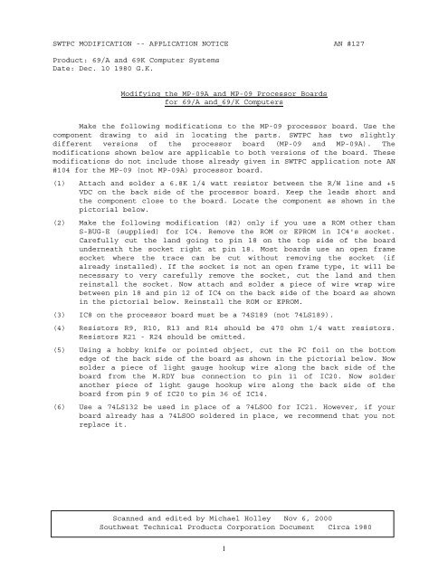
SWTPC MODIFICATION -- APPLICATION NOTICE <strong>AN</strong> #<strong>127</strong><br />
Product: <strong>69</strong>/A <strong>and</strong> <strong>69</strong>K Computer Systems<br />
Date: Dec. 10 1980 G.K.<br />
<strong>Modifying</strong> <strong>the</strong> <strong>MP</strong>-<strong><strong>09</strong>A</strong> <strong>and</strong>_<strong>MP</strong>-<strong>09</strong> <strong>Processor</strong> <strong>Boards</strong><br />
<strong>for</strong> <strong>69</strong>/A <strong>and</strong>_<strong>69</strong>/K Computers<br />
Make <strong>the</strong> following modifications to <strong>the</strong> <strong>MP</strong>-<strong>09</strong> processor board. Use <strong>the</strong><br />
component drawing to aid in locating <strong>the</strong> parts. SWTPC has two slightly<br />
different versions of <strong>the</strong> processor board (<strong>MP</strong>-<strong>09</strong> <strong>and</strong> <strong>MP</strong>-<strong><strong>09</strong>A</strong>). The<br />
modifications shown below are applicable to both versions of <strong>the</strong> board. These<br />
modifications do not include those already given in SWTPC application note <strong>AN</strong><br />
#104 <strong>for</strong> <strong>the</strong> <strong>MP</strong>-<strong>09</strong> (not <strong>MP</strong>-<strong><strong>09</strong>A</strong>) processor board.<br />
(1) Attach <strong>and</strong> solder a 6.8K 1/4 watt resistor between <strong>the</strong> R/W line <strong>and</strong> +5<br />
VDC on <strong>the</strong> back side of <strong>the</strong> processor board. Keep <strong>the</strong> leads short <strong>and</strong><br />
<strong>the</strong> component close to <strong>the</strong> board. Locate <strong>the</strong> component as shown in <strong>the</strong><br />
pictorial below.<br />
(2) Make <strong>the</strong> following modification (#2) only if you use a ROM o<strong>the</strong>r than<br />
S-BUG-E (supplied) <strong>for</strong> IC4. Remove <strong>the</strong> ROM or EPROM in IC4's socket.<br />
Carefully cut <strong>the</strong> l<strong>and</strong> going to pin 18 on <strong>the</strong> top side of <strong>the</strong> board<br />
underneath <strong>the</strong> socket right at pin 18. Most boards use an open frame<br />
socket where <strong>the</strong> trace can be cut without removing <strong>the</strong> socket (if<br />
already installed). If <strong>the</strong> socket is not an open frame type, it will be<br />
necessary to very carefully remove <strong>the</strong> socket, cut <strong>the</strong> l<strong>and</strong> <strong>and</strong> <strong>the</strong>n<br />
reinstall <strong>the</strong> socket. Now attach <strong>and</strong> solder a piece of wire wrap wire<br />
between pin 18 <strong>and</strong> pin 12 of IC4 on <strong>the</strong> back side of <strong>the</strong> board as shown<br />
in <strong>the</strong> pictorial below. Reinstall <strong>the</strong> ROM or EPROM.<br />
(3) IC8 on <strong>the</strong> processor board must be a 74S189 (not 74LS189).<br />
(4) Resistors R9, R10, R13 <strong>and</strong> R14 should be 470 ohm 1/4 watt resistors.<br />
Resistors R21 - R24 should be omitted.<br />
(5) Using a hobby knife or pointed object, cut <strong>the</strong> PC foil on <strong>the</strong> bottom<br />
edge of <strong>the</strong> back side of <strong>the</strong> board as shown in <strong>the</strong> pictorial below. Now<br />
solder a piece of light gauge hookup wire along <strong>the</strong> back side of <strong>the</strong><br />
board from <strong>the</strong> M.RDY bus connection to pin 11 of IC20. Now solder<br />
ano<strong>the</strong>r piece of light gauge hookup wire along <strong>the</strong> back side of <strong>the</strong><br />
board from pin 9 of IC20 to pin 36 of IC14.<br />
(6) Use a 74LS132 be used in place of a 74LSOO <strong>for</strong> IC21. However, if your<br />
board already has a 74LSOO soldered in place, we recommend that you not<br />
replace it.<br />
Scanned <strong>and</strong> edited by Michael Holley Nov 6, 2000<br />
Southwest Technical Products Corporation Document Circa 1980<br />
1
(7) Cut <strong>the</strong> PC foil trace going to pin 2 of IC20. This cut should be made on <strong>the</strong><br />
BOTTOM side of <strong>the</strong> board. Be careful to cut only <strong>the</strong> trace that runs between<br />
pin 2 <strong>and</strong> <strong>the</strong> heavier ground foil. Do not cut <strong>the</strong> heavy ground foil.<br />
(8) Solder a piece of light gauge wire along <strong>the</strong> back side of <strong>the</strong> board from pin<br />
2 of IC20 to pin 4 of IC6.<br />
2