


You also want an ePaper? Increase the reach of your titles
YUMPU automatically turns print PDFs into web optimized ePapers that Google loves.
ME 341 Mechanics of Machine Elements <br />
<strong>Clarkson</strong> <strong>University</strong>, Fall 10', Prof. Yurgartis <br />
First Hour Exam 9/ 1711 0 (Exam 112) <br />
Open textbook, closed notes. Good luck!<br />
Short answer questions (8 pts each)<br />
1. Why are factors of safety used in design, and where do the values come from<br />
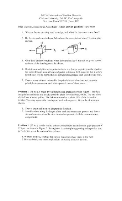
2. Do the stress elements shown below have the same state of stress Explain your<br />
answer.<br />
3. Give three distinct conditions when the equation Me/I may fail to give a COlTect<br />
estimate of the bending stress in a beam.<br />
4. If minimum weight is an important criteria in a design, explain how the equation<br />
for shear stress in a round beam subjected to torsion, Tr/J, suggests that a hollow<br />
round shaft will be more efficient at transmitting torque than a solid round shaft.<br />
5. Draw a stress element oriented in the principle axes direction, and show the<br />
principle stresses associated with a general case ofplane stress.<br />
Problem 1. (35 pts.) A chain-driven transmission shaft is shown in Figure 1. Previous<br />
analysis has estimated at a steady speed the chain force is about 360 lbs. The end of the<br />
shaft drives a belted pulley. The belt return tension is about 10% of the drive side<br />
tension. You may assume the bearings act as simple supports. Given the dimensions<br />
shown,<br />
I. Draw a shear and moment diagram for the shaft.<br />
2. Identify where along the length of the shaft the stresses are greatest and draw a<br />
stress element to show the direction and magnitude of all the non-zero stress<br />
components.<br />
Problem 2. (25 pts.) A thin-walled pressurized cylinder has an internal gage pressure of<br />
125 psi., as shown in Figure 2. An engineer is contemplating putting an inspection port<br />
(a "hole") in about the center of the cylinder.<br />
1. Without the hole, estimate the current maximum shear stress in the wall.<br />
2. Discuss briefly the stress implications of putting a hole in the wall.
¢ . ~oo<br />
D<br />
t ~<br />
.\5<br />
d. ::- (2.<br />
...<br />
¢ t .O rOF-1<br />
12.5 ps,<br />
, . ,<br />
'-'
Exam 112, Problem 1 solution<br />
From a FBD of the sprocket it is determined that the torque transmitted by the shaft is 750<br />
in-lb.<br />
T := 360· 1.5 T = 540<br />
From a FBD of the pulley is is determined that.<br />
0 := I T = 540+ (.18)( 3)-8·3•<br />
2.00<br />
S-'tO<br />
8 := 200 so Rd := 220<br />
From the FBD of the shaft it can be determined that,<br />
Rc := 380 and Ra := 200 M<br />
So the bending moment at bearing Cis:<br />
And the bending moment at the gear B is Mb := 360· 1<br />
Therefore the largest bending stress will be at the bearing C.<br />
The cross section properties of the shaft are,<br />
4<br />
.6 1 : = _TI-,(_c·_2'--)<br />
c := - I = 0.006362 J := J·2 J = 0.0 13<br />
2 64<br />
The stresses at bearing C caused by the bending moment and the torque are ,<br />
T· c <br />
T xy := -J<br />
T xy = 12732<br />
CT = 20749<br />
X<br />
12. -r~z..
Problem 2, exam 112<br />
Th is is a thin walled pressure cyl inder <br />
t := .15 <br />
p := 125 <br />
3 <br />
(Jt = 5.063 x 10 <br />
The longitudinal stress is tensile, but smaller than the tangential stress (about half), so<br />
3 <br />
T max = 2 .53 1 x 10 <br />
Putting a hole in the wall will cause a stress concentration, on the order of 3.


