Download a datasheet for the LABO Temperature Switch here..
Download a datasheet for the LABO Temperature Switch here..
Download a datasheet for the LABO Temperature Switch here..

You also want an ePaper? Increase the reach of your titles
YUMPU automatically turns print PDFs into web optimized ePapers that Google loves.
Honsberg Instruments GmbH<br />
Tenter Weg 2-8 ● 42897 Remscheid ● Germany<br />
Fon +49 (0) 2191 - 9672 - 0 ● Fax - 40<br />
www.honsberg.com ● info@honsberg.com<br />
Product In<strong>for</strong>mation<br />
Dimensions<br />
Optional accessories<br />
Weld-on adapter<br />
Crimp screw joint<br />
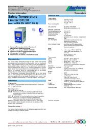
<strong>LABO</strong>-T012-S<br />
status during <strong>the</strong> teach-in, <strong>the</strong> device can be provided ex-works<br />
with a teach-offset. The teach-offset point is added to <strong>the</strong> currently<br />
measured value be<strong>for</strong>e saving.<br />
Example: The switching value is to be set to 80 °C, because at this<br />
temperature a critical process status is to be notified. However,<br />
only 60 °C can be achieved without danger. In this case, <strong>the</strong> device<br />
would be ordered with a "teach-offset" of +20 °C. At 60 °C in <strong>the</strong><br />
process, a switching value of 80 °C would <strong>the</strong>n be stored during<br />
"teaching".<br />
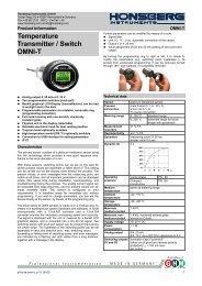
The <strong>LABO</strong>-T012-S limit switch can be used to monitor minima or<br />
minima or maxima.<br />
With a minimum-switch, falling below <strong>the</strong> limit value causes a<br />
switchover to <strong>the</strong> alarm state. Return to <strong>the</strong> normal state occurs<br />
when <strong>the</strong> limit value plus <strong>the</strong> set hysteresis is once more exceeded.<br />
T<br />
stainless steel<br />
Flange mounting<br />
plastic<br />
Compression fitting<br />
plastic<br />
switchover to <strong>the</strong> alarm state. Return to <strong>the</strong> normal state occurs<br />
when <strong>the</strong> measured value once more falls below <strong>the</strong> limit value<br />
minus <strong>the</strong> set hysteresis.<br />
T<br />
Handling and operation<br />
Installation<br />
W<strong>here</strong>ver possible, <strong>the</strong> sensor<br />
tip should be positioned in <strong>the</strong><br />
middle of <strong>the</strong> pipe. When a<br />
flow is present, it should<br />
impinge onto <strong>the</strong> X, in order to<br />
achieve <strong>the</strong> lowest possible<br />
response time.<br />
Avoid bubbles or deposits on <strong>the</strong> sensor. It is <strong>the</strong>re<strong>for</strong>e best to<br />
install at <strong>the</strong> side. The stainless steel threaded connection is first<br />
tightened by hand, and <strong>the</strong>n by 1 / 4 of a turn, using a spanner. The<br />
connection ring of <strong>the</strong> threaded connection can <strong>the</strong>n no longer be<br />
removed from <strong>the</strong> sensor, and <strong>the</strong> immersion depth can <strong>the</strong>re<strong>for</strong>e<br />
not be changed fur<strong>the</strong>r.<br />
Operation and programming<br />
Marking<br />
Flow<br />
The switching value can be set by <strong>the</strong> user by means of teaching.<br />
For this, proceed as follows:<br />
● The temperature which is to be set is applied to <strong>the</strong> device.<br />
● Apply a pulse of at least 0.5 seconds and max. 2 seconds duration<br />
to pin 2 (e.g. via a bridge to <strong>the</strong> supply voltage or a pulse<br />
from <strong>the</strong> PLC), in order to accept <strong>the</strong> measured value.<br />
● When <strong>the</strong> teaching is complete, pin 2 should be connected to<br />
0 V, so as to prevent unintended programming.<br />
The device has a yellow LED which flashes during <strong>the</strong><br />
programming pulse. During operation, <strong>the</strong> LED serves as a status<br />
display <strong>for</strong> <strong>the</strong> switching output.<br />
In order to avoid <strong>the</strong> need to transit to an undesired operating<br />
x<br />
Max<br />
Max-Hyst<br />
A switchover delay time (t DS) can be applied to <strong>the</strong> switchover to <strong>the</strong><br />
alarm state. Equally, one switch-back delay time (t DR) of several can<br />
be applied to switching back to <strong>the</strong> normal state.<br />
Max<br />
Max-Hyst<br />
T<br />
t DS<br />
t DR<br />
In <strong>the</strong> normal state <strong>the</strong> integrated LED is on, in <strong>the</strong> alarm state it is<br />
off, and this corresponds to its status when <strong>the</strong>re is no supply<br />
voltage.<br />
In <strong>the</strong> non-inverted (standard) model, while in <strong>the</strong> normal state <strong>the</strong><br />
switching output is at <strong>the</strong> level of <strong>the</strong> supply voltage; in <strong>the</strong> alarm<br />
t<br />
t<br />
2 pi-ho-te-etk12-s_e V1.02-00