Product Information
Product Information
Product Information

You also want an ePaper? Increase the reach of your titles
YUMPU automatically turns print PDFs into web optimized ePapers that Google loves.
GHM Messtechnik GmbH<br />
Hans-Sachs-Str. 26 ● 93128 Regenstauf ● Germany<br />
Fon +49 (0) 9402 - 9383 - 0 ● Fax - 33<br />
www.ghm-messtechnik.de ● info@ghm-messtechnik.de<br />
<strong>Product</strong> <strong>Information</strong><br />
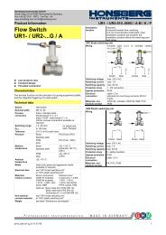
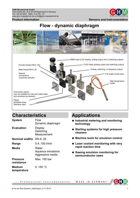
Flow - dynamic diaphragm<br />
Sensors and Instrumentation<br />
OMNI head (LCD display, analog output and 2 switching outputs<br />
Female thread (DN 8..25)<br />
Male thread DN 8..25<br />
Special<br />
connections<br />
(customer specific)<br />
FLEX head (analog output and switching output)<br />
Analog, switching, or frequency output<br />
Full metal construction<br />
High temperature<br />
model<br />
Connection pieces<br />
(can be installed on inlet and outlet sides,<br />
and combined as desired)<br />
Plastic<br />
Nickelled brass<br />
Stainless steel<br />
Characteristics<br />
System<br />
Flow<br />
Dynamic diaphragm<br />
Evaluation Display<br />
Switching<br />
Measurement<br />
Nominal widths DN 8..25<br />
Range<br />
0.4..100 l/min<br />
Media<br />
Pressure<br />
resistance<br />
Medium<br />
temperature<br />
Water<br />
Aqueous emulsions<br />
Aggressive media<br />
Max. 100 bar<br />
0..150 °C<br />
Applications<br />
● Industrial metering and monitoring<br />
technology<br />
● Starting systems for high pressure<br />
cleaners<br />
● Machine tools for emulsion control<br />
● Laser coolant monitoring with very<br />
rapid reaction time<br />
● Sawing emulsion monitoring for<br />
semiconductor saws<br />
pi-ho-sm-flow-dynamic_diaphragm_e V1.00-01 1
GHM Messtechnik GmbH<br />
Hans-Sachs-Str. 26 ● 93128 Regenstauf ● Germany<br />
Fon +49 (0) 9402 - 9383 - 0 ● Fax - 33<br />
www.ghm-messtechnik.de ● info@ghm-messtechnik.de<br />
<strong>Product</strong> <strong>Information</strong><br />
Function And Benefits<br />
●<br />
●<br />
●<br />
●<br />
●<br />
Very large metering range<br />
Fast response time<br />
Robust with end stop<br />
Lowest dispersal in the series<br />
(100 % individual calibration)<br />
Modular concept<br />
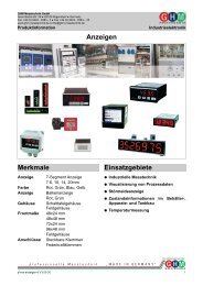
A thin elastic diaphragm made of stainless steel, which covers the<br />
entire flow cross-section, is deflected by the flowing fluid, and<br />
thereby pushes against an arched end stop (therefore,<br />
overexpansion cannot occur!).<br />
Sensors and Instrumentation<br />
Programmability of parameters<br />
All XF sensors from HONSBERG are a part of the family of<br />
intelligent sensors. They have a microcontroller which enables a<br />
multitude of parameter changes.<br />
By standard, all three main electronics have the capability of<br />
making local changes. In addition, a device configurator can be<br />
used to change all saved parameters of a device at any time, if<br />
desired or necessary.<br />
LABO-XF<br />
- / U / F / C / S<br />
Flow<br />
Diaphragm<br />
Magnet<br />
There is a plastic-coated magnet on the diaphragm. When there is<br />
a deflection, its magnetic field changes, and this is detected by a<br />
sensor outside the area of flow.<br />
Flexible diaphragm made of stainless<br />
steel, with plastic-coated magnet.<br />
End stop<br />
FLEX-XF<br />
OMNI-XF<br />
Pulse programming on pin 2:<br />
Apply the supply voltage level for 1 second and<br />
save the current value as the full scale value (for<br />
analog outputs) or as a switching value (for limit<br />
switches).<br />
Programming with magnet clip:<br />
Hold the magnet to the marking for 1 second and<br />
save the present value as the full scale value (for<br />
analog outputs) or as a switching value (for limit<br />
switches).<br />
Since the diaphragm only bends, and functions without a bearing,<br />
there is almost no frictional effect and extremely little wear.<br />
The movement occurs practically free of hysteresis, and the test<br />
results have very good reproducibility. The diaphragms low bulk<br />
results in a rapid response time. The almost complete covering of<br />
the flow cross-section in the neutral position enables a very low<br />
metering range start value.<br />
The evaluation of the entire flow cross-section means that there are<br />
no problems when routing pipes. Run-in and run-out sections are<br />
not necessary. The shaped end stop and the elastic properties of<br />
the diaphragm mean that even severe water hammer causes no<br />
damage. The low number of parts coming into contact with the<br />
medium as well as the bend of the diaphragm guarantee a low<br />
tendency towards soiling and material adhesion. The flange<br />
construction simplifies installation and service.<br />
ECI-1<br />
Programming with magnet ring:<br />
With the aid of the display and of the movable<br />
ring, numerous parameters can be conveniently<br />
set on the spot.<br />
Through a range of options, the XF system is flexibly adaptable to<br />
very varied requirements.<br />
●<br />
●<br />
●<br />
●<br />
The widest range of materials and connection possibilities.<br />
High-temperature model<br />
Resistance to backflows<br />
Minimum value measurement<br />
If required, all parameters can be set at any time<br />
on all intelligent sensors, using the ECI-1 device<br />
configurator.<br />
Universal switching outputs<br />
The push-pull transistor outputs enable the simplest installation.<br />
You install the output like an NPN switch and it is an NPN switch;<br />
you install the output like a PNP switch and it is a PNP<br />
switch – without programming or wire breaks.<br />
You are assured a resistance to short circuits and pole reversal and<br />
an overload or short circuit is also shown in the display with OMNI<br />
electronics.<br />
2 pi-ho-sm-flow-dynamic_diaphragm_e V1.00-01
GHM Messtechnik GmbH<br />
Hans-Sachs-Str. 26 ● 93128 Regenstauf ● Germany<br />
Fon +49 (0) 9402 - 9383 - 0 ● Fax - 33<br />
www.ghm-messtechnik.de ● info@ghm-messtechnik.de<br />
<strong>Product</strong> <strong>Information</strong><br />
Device overview<br />
Sensors and Instrumentation<br />
Device<br />
Range l/min<br />
Pressure resistance<br />
in bar<br />
Medium<br />
temperature<br />
Supply voltage<br />
Displays<br />
Switching<br />
Output signal<br />
Measuring<br />
Page<br />
LABO-XF-S 0.6..80<br />
(0.4..100)<br />
PN 16..100 0..70 °C<br />
(150 °C)<br />
10..30<br />
V DC<br />
Signal<br />
LED<br />
1 x<br />
Push-<br />
Pull<br />
- 4<br />
LABO-XF-I 0.6..80<br />
(0.4..100)<br />
PN 16..100 0..70 °C<br />
(150 °C)<br />
10..30<br />
V DC<br />
Signal<br />
LED<br />
- 4..20 mA 9<br />
LABO-XF-U 0.6..80<br />
(0.4..100)<br />
PN 16..100 0..70 °C<br />
(150 °C)<br />
15..30<br />
V DC<br />
Signal<br />
LED<br />
- 0..10 V 9<br />
LABO-XF-F 0.6..80<br />
(0.4..100)<br />
PN 16..100 0..70 °C<br />
(150 °C)<br />
10..30<br />
V DC<br />
Signal<br />
LED<br />
- Frequency<br />
0..2 kHz<br />
(push-pull)<br />
9<br />
LABO-XF-C 0.6..80<br />
(0.4..100)<br />
PN 16..100 0..70 °C<br />
(150 °C)<br />
10..30<br />
V DC<br />
Signal<br />
LED<br />
- X pulses /<br />
litre<br />
(push-pull)<br />
9<br />
FLEX-XF 0.6..80<br />
(0.4..100)<br />
PN 16..100 0..70 °C<br />
(150 °C)<br />
18..30<br />
V DC<br />
Signal<br />
LED<br />
1 x<br />
Push-Pull<br />
0/4..20 mA<br />
0..10 V<br />
or<br />
0..2 kHz<br />
13<br />
OMNI-XF 0.6..80<br />
(0.4..100)<br />
PN 16..100 0..70 °C<br />
(150 °C)<br />
18..30<br />
V DC<br />
Graphic LCD<br />
illuminated<br />
transflective<br />
and<br />
signal LED<br />
2 x<br />
Push-Pull<br />
0/4..20 mA<br />
or<br />
0..10 V<br />
18<br />
OMNI-C-XF<br />
(counter)<br />
Totaliser / consumption<br />
counter from<br />
one<br />
increment to<br />
9999 m³<br />
PN 16..100 0..70 °C<br />
(150 °C)<br />
18..30<br />
V DC<br />
Graphic LCD<br />
illuminated<br />
transflective<br />
and<br />
signal LED<br />
2 x<br />
Push-Pull<br />
- 23<br />
ECI-1 All LABO, FLEX, and OMNI parameters can be set or modified using the ECI-1 configurator. 27<br />
Options<br />
Accessories<br />
● LABO transmitter – Temperature up to 150 °<br />
● OMNI – Tropical model<br />
●<br />
●<br />
●<br />
●<br />
●<br />
●<br />
Errors and technical modifications reserved.<br />
Type ZV / ZE (Filter)<br />
KB.... (Round plug connector 4/5-pin)<br />
OMNI-TA (Panel meter)<br />
OMNI-C-TA (Panel counter)<br />
OMNI-remote<br />
EEZ-904 (External universal counter)<br />
28<br />
29<br />
pi-ho-sm-flow-dynamic_diaphragm_e V1.00-01 3
Honsberg Instruments GmbH<br />
Tenter Weg 2-8 ● 42897 Remscheid ● Germany<br />
Fon +49 (0) 2191 - 9672 - 0 ● Fax - 40<br />
www.honsberg.com ● info@honsberg.com<br />
<strong>Product</strong> <strong>Information</strong><br />
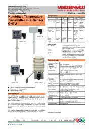
Flow Switch LABO-XF-S<br />
Sensors and Instrumentation<br />
The shaped end stop and the elastic properties of the diaphragm<br />
mean that even severe water hammer causes no damage. The low<br />
number of media contact parts guarantees reliable operation and a<br />
low tendency to contamination.<br />
There are flanged connection pieces on the inlet and outlet; these<br />
are available in various nominal widths and materials. By removing<br />
the four bolts of the flange connection, it is simple to remove the<br />
measurement unit for servicing, while the connections remain in the<br />
pipework.<br />
Technical data<br />
● Very short response time<br />
● High overload protection<br />
● Metering range 1:80<br />
● Low pressure loss<br />
● Compact design<br />
Characteristics<br />
A thin elastic diaphragm made of stainless steel, which covers the<br />
entire flow cross-section, is deflected by the flowing fluid, and<br />
thereby pushes against an arched end stop.<br />
Diaphragm<br />
Flow<br />
Magnet<br />
There is a plastic-coated magnet on the diaphragm. When there is<br />
a deflection, its magnetic field changes, and this is detected by a<br />
sensor outside the area of flow.<br />
Flexible diaphragm made of stainless<br />
steel, with plastic-coated magnet.<br />
End stop<br />
The integrated converter / counter make available an electronic<br />
switching output (push-pull) with adjustable characteristics<br />
(minimum/maximum) and hysteresis, which responds when an<br />
adjustable limit is fallen short of or exceeded. If desired, the<br />
switching value can be set to the currently existing flow using<br />
"teaching".<br />
Models with analog or pulse output are also available (see separate<br />
data sheets). Because the diaphragm only bends, and functions<br />
without a bearing, there is almost no friction effect. The movement<br />
therefore occurs practically free of hysteresis, and the switching<br />
point has very good reproducibility.<br />
The diaphragm's low bulk results in a short response time. The<br />
almost complete covering of the flow cross-section in the neutral<br />
position enables a very low response threshold. As soon as the<br />
slightest flow exists, the diaphragm is of necessity deflected. The<br />
evaluation of the entire flow cross-section means that there are no<br />
problems when routing pipes. Run-in and run-out sections are not<br />
necessary.<br />
Sensor<br />
dynamic diaphragm<br />
Nominal width DN 8..25<br />
Process<br />
connection<br />
female thread G 1 / 4..G 1,<br />
optionally male thread or hose nozzle<br />
Switching ranges 1..100 l/min (water)<br />
for standard range see table "Ranges",<br />
minimum value range 0.4..6 l/min<br />
optionally available<br />
Measurement<br />
accuracy<br />
Standard ranges:<br />
±3 % of the measured value,<br />
minimum 0.25 l/min<br />
Minimum value range:<br />
±3 % of the measured value,<br />
minimum 0.1 l/min<br />
Pressure loss max. 0.5 bar at the end of the metering<br />
range<br />
Pressure<br />
Plastic construction: PN 16 bar<br />
resistance Full metal construction: PN 100 bar<br />
Media temperature 0..70 °C<br />
with high temperature option 0..150 °C<br />
Ambient<br />
0..70 °C<br />
temperature<br />
Storage<br />
-20..+80 °C<br />
temperature<br />
Materials<br />
medium-contact<br />
Materials, nonmedium-contact<br />
Supply voltage<br />
Power<br />
consumption<br />
Switching output<br />
Display<br />
Body:<br />
PPS,<br />
CW614N nickelled or<br />
stainless steel 1.4404<br />
Connections: POM,<br />
CW614N nickelled or<br />
stainless steel 1.4404<br />
Seals:<br />
FKM<br />
Diaphragm: stainless steel 1.4031k<br />
Magnet holder: PPS<br />
Adhesive: epoxy resin<br />
Sensor tube: CW614N nickelled<br />
Adhesive: epoxy resin<br />
Flange bolts stainless steel<br />
Full metal construction:<br />
steel<br />
10..30 V DC<br />
< 1 W (for no-load outputs)<br />
transistor output "push-pull"<br />
(resistant to short circuits and polarity<br />
reversal) l out = 100 mA max.<br />
yellow LED<br />
(On = Normal / Off = Alarm /<br />
rapid flashing = programming)<br />
for round plug connector M12x1, 4-pole<br />
Electrical<br />
connection<br />
Ingress protection IP 67<br />
Weight<br />
see table "Dimensions and weights"<br />
Conformity CE<br />
4 pi-ho-sm-flow-dynamic_diaphragm_e V1.00-01
Honsberg Instruments GmbH<br />
Tenter Weg 2-8 ● 42897 Remscheid ● Germany<br />
Fon +49 (0) 2191 - 9672 - 0 ● Fax - 40<br />
www.honsberg.com ● info@honsberg.com<br />
<strong>Product</strong> <strong>Information</strong><br />
Ranges<br />
Dimensions and weights<br />
Sensors and Instrumentation<br />
Nominal width Switching range<br />
l/min H 2O<br />
Q max<br />
recommended<br />
DN 8..25 0.4.. 6.0 120<br />
DN 8..25 • 1.0.. 15.0<br />
DN 10.0.25 • 1.0.. 25.0<br />
DN 15.0.25 • 1.0.. 50.0<br />
DN 20.0.25 • 1.0.. 80.0<br />
DN 25 * 1.0..100.0<br />
* Inner pipe diameter ≥ Ø22.5<br />
Special ranges are available.<br />
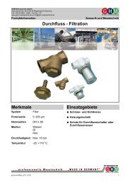
Wiring<br />
1<br />
2<br />
3<br />
4<br />
brown<br />
white<br />
blue<br />
black<br />
Z=Load<br />
Z<br />
Z<br />
10..30 V DC<br />
programming<br />
0 V<br />
switching output<br />
Connection example:<br />
2<br />
3<br />
1<br />
4<br />
PNP<br />
NPN<br />
Before the electrical installation, it must be ensured that the supply<br />
voltage corresponds to the data sheet.<br />
It is recommended to use shielded wiring.<br />
The push-pull output) can as desired be switched as a PNP or an<br />
NPN output.<br />
Connection pieces<br />
G DN L B X ØD Weight*<br />
Metal / kg<br />
Plastic Metal / plastic<br />
G 1 / 4 DN 8 26 12 12 22,5 / 33 0.245 / 0.055<br />
G 3 / 8 DN 10 0.240 / 0.050<br />
G 1 / 2 DN 15 28 14 14 28,0 / 37 0.250 / 0.055<br />
G 3 / 4 DN 20 30 16 16 35,0 / 42 0.270 / 0.060<br />
G 1 DN 25 - 18 - 0.400 / 0.085<br />
G 1 / 4 A DN 8 26 - 12 - 0.230 / 0.045<br />
G 3 / 8 A DN 10 - - 0.230 / 0.045<br />
G 1 / 2 A DN 15 28 - 14 - 0.240 / 0.050<br />
G 3 / 4 A DN 20 30 - 16 - 0.235 / 0.050<br />
G 1 A DN 25 32 - 18 - 0.235 / 0.050<br />
*Weights per connection, excluding bolts<br />
Body<br />
Construction<br />
Weight*<br />
kg<br />
Plastic ca. 0.100<br />
Metal ca. 0.400<br />
*Weights incl. internal parts, sensor and bolts for connection pieces<br />
pi-ho-sm-flow-dynamic_diaphragm_e V1.00-01 5
Honsberg Instruments GmbH<br />
Tenter Weg 2-8 ● 42897 Remscheid ● Germany<br />
Fon +49 (0) 2191 - 9672 - 0 ● Fax - 40<br />
www.honsberg.com ● info@honsberg.com<br />
<strong>Product</strong> <strong>Information</strong><br />
Options<br />
Through a range of options, the XF system is flexibly adaptable to<br />
very varied requirements.<br />
Full metal construction<br />
The standard version has a plastic body with a pressure resistance<br />
of 16 bar. A metalled body (nickelled brass) with a pressure<br />
resistance of 100 bar is optionally available. The higher operating<br />
pressure requires a combination with metal connection pieces.<br />
Switching value settings in the range 1..80 l/min are possible.<br />
High temperature<br />
If the full metal model with high temperature sensors is fitted,<br />
operation at media temperatures up to 150 °C is possible. Here, the<br />
primary sensor element is located in the housing of the<br />
measurement unit, while the converter / counter are located away<br />
from housing via a 50 cm long heat-resistant cable.<br />
Note:Operation using the plastic body is also possible at<br />
temperatures greater than 70 °C. However, it should be noted that<br />
this reduces the stability to pressure .<br />
Resistance to backflows<br />
With forward flows, the diaphragm pushes against an arched end<br />
stop, and is undamaged by flow rates which are significantly higher<br />
than the intended metering range, or by water hammer. For flows or<br />
pressure surges in the reverse direction, in the standard version the<br />
diaphragm pushes against a circumferential plastic support ring,<br />
and almost completely closes the flow cross-section. This causes<br />
pressure to build up which can damage the diaphragm. In<br />
applications where such conditions can arise (e.g. from elastic<br />
hoses to the rear of the measuring equipment) the use of the<br />
"resistance to backflows" option is recommended. Here, the plastic<br />
support ring is replaced by another arched end stop made of<br />
stainless steel, so that the diaphragm is provided with the same<br />
overload and pressure surge resistance in the reverse direction as<br />
in the forward direction. However, a switching value setting in the<br />
reverse direction is not possible.<br />
The "resistance to backflows" option is mandatory for bodies made<br />
of metal.<br />
Minimum value measurement<br />
For switching ranges up to 6 l/min, the sensitivity and therefore the<br />
stability of the measuring system can be increased, and so<br />
switching value settings even less than 1 l/min, i.e. from 0.4 l/min<br />
become possible. For this, the sensor is installed on the opposite<br />
side of the housing. This option is not available for metal housings<br />
and models with resistance to backflows.<br />
Sensors and Instrumentation<br />
normal with a flanged part, the body can be pulled out without<br />
loosening the screw connections.<br />
Note<br />
The switching value can be programmed by the user via "teaching".<br />
If desired, programmability can be blocked by the manufacturer.<br />
The ECI-1 device configurator with associated software is available<br />
as a convenient option for programming all parameters by PC, and<br />
for adjustment.<br />
Operation and programming<br />
The switching value is set as follows:<br />
● Apply the flow rate to be set to the device.<br />
● Apply an impulse of at least 0.5 seconds and max. 2 seconds<br />
duration to pin 2 (e.g. via a bridge to the supply voltage or a<br />
pulse from the PLC), in order to accept the measured value.<br />
● When the teaching is complete, pin 2 should be connected to<br />
0 V, so as to prevent unintended programming.<br />
The device has a yellow LED which flashes during the<br />
programming pulse. During operation, the LED serves as a status<br />
display for the switching output.<br />
In order to avoid the need to transit to an undesired operating<br />
status during the teach-in, the device can be provided ex-works<br />
with a teach-offset. The teach-offset point is added to the currently<br />
measured value before saving. The offset point can be positive or<br />
negative.<br />
Example: The switching value should be set to 80 l/min. However,<br />
it is possible only to reach 60 l/min without problems. In this case,<br />
the device would be set using a teach-offset of +20 l/min. At a flow<br />
rate of 60 l/min in the process, teaching would then store a value of<br />
80 l/min.<br />
The limit switch can be used to monitor minima or maxima.<br />
With a minimum-switch, falling below the limit value causes a<br />
switchover to the alarm state. Return to the normal state occurs<br />
when the limit value plus the set hysteresis is once more exceeded.<br />
T<br />
Handling and operation<br />
Installation<br />
The device is supplied with connection pieces mounted. These may<br />
be removed for the installation in the pipework.<br />
The sensor can be operated in any location. However, the lowest<br />
tendency to contamination occurs when the diaphragm swings from<br />
bottom to top. If possible. installation should therefore be made<br />
either with flow from bottom to top, or horizontal. In the latter case,<br />
the sensor in the minimum value range model (max. 6 l/min, see<br />
options) should point downwards; for all other versions it should<br />
point upwards. Factory adjustment is made with flow horizontal.<br />
It should be ensured that the sensor is installed in the direction of<br />
the flow arrow. In spite of its low bulk, the diaphragm is very robust;<br />
nevertheless it should not be buckled or compressed through force<br />
during installation or removal.<br />
The bolts in the housing pass all the way through it, and must be<br />
completely removed if the sensor body is replaced. Afterwards, as<br />
Min+Hyst<br />
Min<br />
t<br />
6 pi-ho-sm-flow-dynamic_diaphragm_e V1.00-01
Honsberg Instruments GmbH<br />
Tenter Weg 2-8 ● 42897 Remscheid ● Germany<br />
Fon +49 (0) 2191 - 9672 - 0 ● Fax - 40<br />
www.honsberg.com ● info@honsberg.com<br />
<strong>Product</strong> <strong>Information</strong><br />
With a maximum-switch, exceeding the limit value causes a<br />
switchover to the alarm state. Return to the normal state occurs<br />
when the measured value once more falls below the limit value<br />
minus the set hysteresis.<br />
T<br />
Sensors and Instrumentation<br />
Ordering code<br />
1. 2. 3. 4. 5. 6. 7. 8.<br />
LABO - XF- S<br />
9. 10. 11. 12. 13.<br />
S<br />
Max<br />
Max-Hyst<br />
A switchover delay time (t DS) can be applied to the switchover to the<br />
alarm state. Equally, one switch-back delay time (t DR) of several can<br />
be applied to switching back to the normal state.<br />
Max<br />
Max-Hyst<br />
T<br />
In the normal state the integrated LED is on, in the alarm state it is<br />
off, and this corresponds to its status when there is no supply<br />
voltage.<br />
In the non-inverted (standard) model, while in the normal state the<br />
switching output is at the level of the supply voltage; in the alarm<br />
state it is at 0 V, so that a wire break would also display as an alarm<br />
state at the signal receiver. Optionally, an inverted switching output<br />
can also be provided, i.e. in the normal state the output is at 0 V,<br />
and in the alarm state it is at the level of the supply voltage.<br />
non-inverted output<br />
inverted output<br />
A Power-On-Delay function (ordered as a separate option) makes it<br />
possible to maintain the switching output in the normal state for a<br />
defined period after application of the supply voltage.<br />
t<br />
t<br />
t<br />
= Option<br />
1. Switching output (Limit switch)<br />
S push-pull (compatible with PNP and NPN)<br />
2. Nominal width<br />
008 DN 8 - G 1 / 4<br />
010 DN 10 - G 3 / 8<br />
015 DN 15 - G 1 / 2<br />
020 DN 20 - G 3 / 4<br />
025 DN 25 - G 1<br />
3. Process connection<br />
G female thread<br />
A male thread<br />
T hose nozzle<br />
4. Connection material<br />
M CW614N nickelled<br />
P POM<br />
K stainless steel<br />
5. Body material<br />
Q PPS<br />
M CW614N nickelled<br />
K stainless steel<br />
6. Switching range<br />
006<br />
minimum value<br />
<br />
0.4.. 6.0 l/min<br />
• • • • • •<br />
015 1.0.. 15.0 l/min • • • • • • • •<br />
025 1.0.. 25.0 l/min • • • • • • •<br />
050 1.0.. 50.0 l/min • • • • • •<br />
080 1.0.. 80.0 l/min • • • • •<br />
100 1.0..100.0 l/min • • • •<br />
7. Seal material<br />
V FKM<br />
E EPDM<br />
N NBR<br />
8. Resistance to backflows<br />
O without resistance to backflows •<br />
R with resistance to backflows • • •<br />
9. Programming<br />
N cannot be programmed (no teaching)<br />
P programmable (teaching possible)<br />
10. Switching function<br />
L minimum-switch<br />
H maximum-switch<br />
11. Switching signal<br />
O standard<br />
I inverted<br />
12. Electrical connection<br />
S for round plug connector M12x1, 4-pole<br />
13. Optional<br />
H<br />
<br />
150 °C version (with 300 mm cable,<br />
only for metal housing)<br />
• •<br />
pi-ho-sm-flow-dynamic_diaphragm_e V1.00-01 7
Honsberg Instruments GmbH<br />
Tenter Weg 2-8 ● 42897 Remscheid ● Germany<br />
Fon +49 (0) 2191 - 9672 - 0 ● Fax - 40<br />
www.honsberg.com ● info@honsberg.com<br />
<strong>Product</strong> <strong>Information</strong><br />
Options<br />
Switching delay period (0.0..99.9 s) . s<br />
(from Normal to Alarm)<br />
Switch-back delay period (0.0..99.9 s) . s<br />
(from Alarm to Normal)<br />
Sensors and Instrumentation<br />
Accessories<br />
● Cable/round plug connector (KB...)<br />
see additional information “Accessories”<br />
● Device configurator ECI-1<br />
Power-On-Delay period (0..99 s)<br />
(after connecting the supply, time during<br />
which the switching output is not activated)<br />
Switching output fixed at<br />
s<br />
l/min<br />
Switching hysteresis %<br />
Standard = 2 % of the metering range<br />
Teach-offset %<br />
(in percent of the metering range)<br />
Standard = 0 %<br />
Further options available on request.<br />
8 pi-ho-sm-flow-dynamic_diaphragm_e V1.00-01
Honsberg Instruments GmbH<br />
Tenter Weg 2-8 ● 42897 Remscheid ● Germany<br />
Fon +49 (0) 2191 - 9672 - 0 ● Fax - 40<br />
www.honsberg.com ● info@honsberg.com<br />
<strong>Product</strong> <strong>Information</strong><br />
Flow Transmitter<br />
LABO-XF-I / U / F / C<br />
Sensors and Instrumentation<br />
hammer causes no damage. The low number of media contact<br />
parts guarantees reliable operation and a low tendency to<br />
contamination.<br />
There are flanged connection pieces on the inlet and outlet; these<br />
are available in various nominal widths and materials. By removing<br />
the four bolts of the flange connection, it is simple to remove the<br />
measurement unit for servicing, while the connections remain in the<br />
pipework.<br />
The LABO-XF electronics make various output signals available:<br />
●<br />
●<br />
●<br />
●<br />
Analog signal 0/4..20 mA (LABO-XF-I)<br />
Analog signal 0/2..10 V (LABO-XF-U)<br />
Frequency signal (LABO-XF-F) or<br />
Value signal Pulse / x Litres (LABO-XF-C)<br />
A model with switching output is also available.<br />
If desired, the range end value can be set to the currently existing<br />
flow using "teaching".<br />
● Very short response time<br />
● High overload protection<br />
● Metering range 1:100<br />
● Low pressure loss<br />
● Compact design<br />
● 0..10 V , 4..20 mA , frequency/pulse output, complete<br />
configurable<br />
Characteristics<br />
A thin elastic diaphragm made of stainless steel, which covers the<br />
entire flow cross-section, is deflected by the flowing fluid, and<br />
thereby pushes against an arched end stop.<br />
Flow<br />
Diaphragm<br />
Magnet<br />
There is a plastic-coated magnet on the diaphragm. When there is<br />
a deflection, its magnetic field changes, and this is detected by a<br />
sensor outside the area of flow.<br />
Flexible diaphragm made of stainless<br />
steel, with plastic-coated magnet.<br />
End stop<br />
Because the diaphragm only bends, and functions without a<br />
bearing, there is almost no frictional effect. The movement<br />
therefore occurs practically free of hysteresis, and the test results<br />
have very good reproducibility. The diaphragm's low bulk results in<br />
a short response time. The almost complete covering of the flow<br />
cross-section in the neutral position produces very high start-up<br />
sensitivity. As soon as the slightest flow exists, the diaphragm is of<br />
necessity deflected. The evaluation of the entire flow cross-section<br />
means that there are no problems when routing pipes. Run-in and<br />
run-out sections are not necessary. The shaped end stop and the<br />
elastic properties of the diaphragm mean that even severe water<br />
Technical data<br />
Sensor<br />
dynamic diaphragm<br />
nominal width DN 8.0.25<br />
Process<br />
connection<br />
female thread G 1 / 4..G 1,<br />
optionally male thread or hose nozzle<br />
Metering ranges 1..100 l/min (water)<br />
for standard ranges, see table "Ranges",<br />
minimum value range 0.4..6 l/min<br />
optionally available<br />
Measurement<br />
accuracy<br />
Standard ranges:<br />
±3 % of the measured value,<br />
minimum 0.25 l/min<br />
Minimum value range:<br />
±3 % of the measured value,<br />
minimum 0.1 l/min<br />
Pressure loss max. 0.5 bar<br />
Pressure<br />
Plastic construction: PN 16 bar<br />
resistance Full metal construction: PN 100 bar<br />
Media<br />
0..70 °C<br />
temperature with high temperature option 0..150 °C<br />
Ambient<br />
0..70 °C<br />
temperature<br />
Storage<br />
-20..+80 °C<br />
temperature<br />
Materials<br />
medium-contact<br />
Materials, nonmedium-contact<br />
Supply<br />
voltage<br />
Power<br />
consumption<br />
Body:<br />
PPS,<br />
CW614N nickelled or<br />
stainless steel 1.4404<br />
Connections: POM,<br />
CW614N nickelled or<br />
stainless steel 1.4404<br />
Seals:<br />
FKM<br />
Diaphragm: stainless steel 1.4031k<br />
Magnet holder: PPS<br />
Adhesive: epoxy resin<br />
Sensor tube: CW614N nickelled<br />
Adhesive: epoxy resin<br />
Flange bolts: stainless steel<br />
full metal construction:<br />
steel<br />
10..30 V DC at voltage output 10 V:<br />
15..30 V DC<br />
< 1 W (for no-load outputs)<br />
pi-ho-sm-flow-dynamic_diaphragm_e V1.00-01 9
Honsberg Instruments GmbH<br />
Tenter Weg 2-8 ● 42897 Remscheid ● Germany<br />
Fon +49 (0) 2191 - 9672 - 0 ● Fax - 40<br />
www.honsberg.com ● info@honsberg.com<br />
<strong>Product</strong> <strong>Information</strong><br />
Output data: all outputs are resistant to short circuits and<br />
reversal polarity protected<br />
Current 4..20 mA (0..20 mA available on request)<br />
output:<br />
Voltage 0..10 V (2..10 V available on request)<br />
output: output current max. 20 mA<br />
Frequency transistor output "push-pull"<br />
output: l out = 100 mA max.<br />
output frequency depends on metering<br />
range, standard is 500 Imp/l<br />
(corresponds to 833.3 Hz at 100 l/min)<br />
minimum value range: 5000 Imp/l<br />
(corresponds to 500 Hz at 6 l/min)<br />
(other frequencies available on request)<br />
Pulse output: transistor output "push-pull"<br />
l out = 100 mA max.<br />
pulse width 50 ms<br />
pulse per volume is to be stated<br />
Display<br />
yellow LCD shows<br />
operating voltage (LABO-XF-I / U) or<br />
output status (LABO-XF-F / C) or<br />
(rapid flashing = programming)<br />
Electrical<br />
for round plug connector M12x1, 4-pole<br />
connection<br />
Ingress protection IP 67<br />
Weight<br />
see table "Dimensions and weights"<br />
Conformity CE<br />
Ranges<br />
Nominal width Switching range<br />
l/min H 2O<br />
Q max<br />
recommended<br />
DN 8..25 0.4.. 6.0 120<br />
DN 8..25 • 1.0.. 15.0<br />
DN 10.0.25 • 1.0.. 25.0<br />
DN 15.0.25 • 1.0.. 50.0<br />
DN 20.0.25 • 1.0.. 80.0<br />
DN 25 * 1.0..100.0<br />
* Inner pipe diameter ≥ Ø22.5<br />
Special ranges are available.<br />
Wiring<br />
1<br />
2<br />
3<br />
4<br />
brown<br />
white<br />
blue<br />
black<br />
Connection example:<br />
2<br />
3<br />
1<br />
4<br />
Z=Load<br />
Z<br />
PNP<br />
Before the electrical installation, it must be ensured that the supply<br />
voltage corresponds to the data sheet.<br />
It is recommended to use shielded wiring.<br />
The push-pull-output) of the frequency output version can as<br />
desired be switched as a PNP or an NPN output.<br />
Z<br />
NPN<br />
10..30 V DC<br />
programming<br />
0 V<br />
signal output<br />
Dimensions and weights<br />
Connection pieces<br />
Sensors and Instrumentation<br />
G DN L B X ØD Weight*<br />
Metal / kg<br />
Plastic Metal / plastic<br />
G 1 / 4 DN 8 26 12 12 22.5 / 33 0.245 / 0.055<br />
G 3 / 8 DN 10 0.240 / 0.050<br />
G 1 / 2 DN 15 28 14 14 28.0 / 37 0.250 / 0.055<br />
G 3 / 4 DN 20 30 16 16 35.0 / 42 0.270 / 0.060<br />
G 1 DN 25 - 18 - 0.400 / 0.085<br />
G 1 / 4 A DN 8 26 - 12 - 0.230 / 0.045<br />
G 3 / 8 A DN 10 - - 0.230 / 0.045<br />
G 1 / 2 A DN 15 28 - 14 - 0.240 / 0.050<br />
G 3 / 4 A DN 20 30 - 16 - 0.235 / 0.050<br />
G 1 A DN 25 32 - 18 - 0.235 / 0.050<br />
*Weights per connection, excluding bolts<br />
Body<br />
Construction<br />
Weight*<br />
kg<br />
Plastic ca. 0.100<br />
Metal ca. 0.400<br />
*Weights incl. internal parts, sensor and bolts for connection pieces<br />
Options<br />
Through a range of options, the XF system is flexibly adaptable to<br />
very varied requirements:<br />
Full metal construction<br />
The standard version has a plastic body with a pressure resistance<br />
of 16 bar. A metalled body (nickelled brassor stainless steel) with a<br />
pressure resistance of 100 bar is optionally available. The higher<br />
operating pressure requires a combination with metal connection<br />
pieces.<br />
Measurements in the range 1..100 l/min are possible.<br />
10 pi-ho-sm-flow-dynamic_diaphragm_e V1.00-01
Honsberg Instruments GmbH<br />
Tenter Weg 2-8 ● 42897 Remscheid ● Germany<br />
Fon +49 (0) 2191 - 9672 - 0 ● Fax - 40<br />
www.honsberg.com ● info@honsberg.com<br />
<strong>Product</strong> <strong>Information</strong><br />
High temperature<br />
If the full metal model with high temperature sensors is fitted,<br />
operation at media temperatures up to 150 °C is possible. Here, the<br />
primary sensor element is located in the housing of the<br />
measurement unit, while the converter / counter are located away<br />
from housing via a 50 cm long heat-resistant cable.<br />
Resistance to backflows<br />
With forward flows, the diaphragm pushes against an arched end<br />
stop, and is undamaged by flow rates which are significantly higher<br />
than the intended metering range, or by water hammer. For flows or<br />
pressure surges in the reverse direction, in the standard version the<br />
diaphragm pushes against a circumferential plastic support ring,<br />
and almost completely closes the flow cross-section. This causes<br />
pressure to build up which can damage the diaphragm. In<br />
applications where such conditions can arise (e.g. from elastic<br />
hoses to the rear of the measuring equipment) the use of the<br />
"resistance to backflows" option is recommended. Here, the plastic<br />
support ring is replaced by another arched end stop made of<br />
stainless steel, so that the diaphragm is provided with the same<br />
overload and pressure surge resistance in the reverse direction as<br />
in the forward direction. However, a measurement in the reverse<br />
direction is not possible.<br />
The "resistance to backflows" option is mandatory for bodies made<br />
of metal.<br />
Minimum value measurement<br />
For metering ranges up to 6 l/min, the sensitivity of the measuring<br />
system can be increased, and so measurements even less than<br />
1 l/min, i.e. from 0.4 l/min become possible. For this, the sensor is<br />
installed on the opposite side of the housing. This option is not<br />
available for metal housings and models with resistance to<br />
backflows.<br />
Handling and operation<br />
Installation<br />
The device is supplied with connection pieces mounted. These may<br />
be removed for the installation in the pipework.<br />
The sensor can be operated in any location. However, the lowest<br />
tendency to contamination occurs when the diaphragm swings from<br />
bottom to top. If possible. installation should therefore be made<br />
either with flow from bottom to top, or horizontal. In the latter case,<br />
the sensor in the minimum value range model (max. 6 l/min, see<br />
options) should point downwards; for all other versions it should<br />
point upwards. Factory adjustment is made with flow horizontal. It<br />
should be ensured that the device is installed in the direction of the<br />
flow arrow. In spite of its low bulk, the diaphragm is very robust;<br />
nevertheless it should not be buckled or compressed through force<br />
during installation or removal.<br />
Note<br />
Sensors and Instrumentation<br />
The metering range end value can be programmed by the user via<br />
"teaching". Requirement for programmability must be stated when<br />
ordering, otherwise the device cannot be programmed. The ECI-1<br />
device configurator with associated software is available as a convenient<br />
option for programming all parameters by PC, and for adjustment.<br />
The teaching option is not available for the pulse output<br />
version.<br />
Operation and programming<br />
The teaching process can be carried out by the user as follows:<br />
● The flow rate to be set is applied to the device.<br />
● Apply an impulse of at least 0.5 seconds and max. 2 seconds<br />
duration to pin 2 (e.g. via a bridge to the supply voltage or a<br />
pulse from the PLC), in order to accept the measured value.<br />
● When the teaching is complete, pin 2 should be connected to<br />
0 V, so as to prevent unintended programming.<br />
The devices have a yellow LED which flashes during the<br />
programming pulse. During operation, the LED serves as an<br />
indicator of operating voltage (for analog output) or of switching<br />
status (for frequency or pulse output).<br />
To avoid the need to transit to an undesired operating status for the<br />
purpose of teaching, the device can be provided ex-works with a<br />
teach-offset. The teach-offset point is added to the currently<br />
measured value before saving. The offset point can be positive or<br />
negative.<br />
Example: The end of the metering range should be set to 80 l/min.<br />
However, it is possible only to reach 60 l/min without problems. In<br />
this case, the device would be set using a teach-offset of +20 l/min.<br />
At a flow rate of 60 l/min in the process, teaching would then store<br />
a value of 80 l/min.<br />
The bolts in the housing pass all the way through it, and must be<br />
completely removed if the sensor body is replaced. Afterwards, as<br />
normal with a flanged part, the body can be pulled out without<br />
loosening the screw connections.<br />
pi-ho-sm-flow-dynamic_diaphragm_e V1.00-01 11
Honsberg Instruments GmbH<br />
Tenter Weg 2-8 ● 42897 Remscheid ● Germany<br />
Fon +49 (0) 2191 - 9672 - 0 ● Fax - 40<br />
www.honsberg.com ● info@honsberg.com<br />
<strong>Product</strong> <strong>Information</strong><br />
Ordering code<br />
LABO -<br />
XF-<br />
1. 2. 3. 4. 5. 6. 7. 8.<br />
9. 10. 11.<br />
S<br />
Required ordering information<br />
For LABO-XF-F:<br />
Output frequency at full scale<br />
Maximum value: 2,000 Hz<br />
Sensors and Instrumentation<br />
For LABO-XF-C:<br />
For the pulse output version, the volume (with numerical value and<br />
unit) which will correspond to one pulse must be stated.<br />
Hz<br />
= Option<br />
1. Signal output<br />
I current output 4..20 mA<br />
U voltage output 0..10 V<br />
F frequency output (see "Ordering information")<br />
C pulse output (see "Ordering information")<br />
2. nominal width<br />
008 DN 8 - G 1 / 4<br />
010 DN 10 - G 3 / 8<br />
015 DN 15 - G 1 / 2<br />
020 DN 20 - G 3 / 4<br />
025 DN 25 - G 1<br />
3. Process connection<br />
G female thread<br />
A male thread<br />
T hose nozzle<br />
4. Connection material<br />
M CW614N nickelled<br />
P POM<br />
K stainless steel<br />
5. Body material<br />
Q PPS<br />
M CW614N nickelled<br />
K stainless steel<br />
6. Metering range<br />
006<br />
minimum value<br />
<br />
0.4.. 6.0 l/min<br />
• • • • • •<br />
015 1.0.. 15.0 l/min • • • • • • • •<br />
025 1.0.. 25.0 l/min • • • • • • •<br />
050 1.0.. 50.0 l/min • • • • • •<br />
080 1.0.. 80.0 l/min • • • • •<br />
100 1.0..100.0 l/min • • • •<br />
7. Seal material<br />
V FKM<br />
E EPDM<br />
N NBR<br />
8. Resistance to backflows<br />
O without resistance to backflows •<br />
R with resistance to backflows • • •<br />
9. Programming<br />
N cannot be programmed (no teaching)<br />
P programmable (teaching possible)<br />
10. Electrical connection<br />
S for round plug connector M12x1, 4-pole<br />
11. Optional<br />
H<br />
150 °C Version<br />
(with 300 mm cable, only for metal<br />
housing)<br />
• •<br />
Volume per pulse (numerical value)<br />
Volume per pulse (unit)<br />
Options<br />
Special range for analog output:<br />
Honsberg Instruments GmbH<br />
Tenter Weg 2-8 ● 42897 Remscheid ● Germany<br />
Fon +49 (0) 2191 - 9672 - 0 ● Fax - 40<br />
www.honsberg.com ● info@honsberg.com<br />
<strong>Product</strong> <strong>Information</strong><br />
Flow Transmitter /<br />
Switch FLEX-XF<br />
Sensors and Instrumentation<br />
The shaped end stop and the elastic properties of the diaphragm<br />
mean that even severe water hammer causes no damage.<br />
The low number of media contact parts guarantees reliable<br />
operation and a low tendency to contamination.<br />
The connection pieces for both sides can be freely selected, and<br />
are flanged on. Various nominal widths and materials are available.<br />
By removing the four bolts of the flange connection, it is simple to<br />
remove the measurement unit for servicing, while the connections<br />
remain in the pipework.<br />
The integrated FLEX-XF converter / counter have an analog output<br />
(4..20 mA or 0..10 V) and a transistor output (push-pull). The<br />
transistor output can be used as a limit switch for monitoring of<br />
minima or maxima, but also as a frequency output.<br />
Technical data<br />
● Universal flow sensor with rapid<br />
dynamic diaphragm<br />
● Switching output and/or analog output<br />
(4..20 mA or 0..10 V)<br />
● Wide measuring range<br />
● Ingress protection IP 67<br />
● Cable outlet infinitely rotatable<br />
● Robust stainless steel housing<br />
Characteristics<br />
A thin elastic diaphragm made of stainless steel, which covers the<br />
entire flow cross-section, is deflected by the flowing fluid, and<br />
thereby pushes against an arched end stop.<br />
Flow<br />
Diaphragm<br />
Magnet<br />
There is a plastic-coated magnet on the diaphragm. When there is<br />
a deflection, its magnetic field changes, and this is detected by a<br />
sensor outside the area of flow.<br />
Flexible diaphragm made of stainless<br />
steel, with plastic-coated magnet.<br />
End stop<br />
Because the diaphragm only bends, and functions without a bearing,<br />
there is almost no frictional effect. The movement therefore occurs<br />
practically free of hysteresis, and the test results have very<br />
good reproducibility. The diaphragm's low bulk results in a rapid response<br />
time.<br />
The almost complete covering of the flow cross-section in the neutral<br />
position allows very high initial sensitivity. As soon as the slightest<br />
flow exists, the diaphragm is of necessity deflected. The evaluation<br />
of the entire flow cross-section means that there are no problems<br />
when routing pipes. Run-in and run-out sections are not necessary.<br />
Sensor<br />
dynamic diaphragm<br />
nominal width DN 8.0.25<br />
Process<br />
connection<br />
female thread G 1 / 4..G 1,<br />
optionally male thread or hose nozzle<br />
Metering ranges 1..100 l/min (water)<br />
for standard ranges, see table "Ranges",<br />
minimum value range 0.4..6 l/min<br />
optionally available<br />
Accuracy<br />
standard ranges:<br />
±3 % of the measured value,<br />
minimum 0.25 l/min<br />
minimum value range:<br />
±3 % of the measured value,<br />
minimum 0.1 l/min<br />
Pressure loss max. 0.5 bar at the end of the metering<br />
range<br />
Pressure<br />
plastic construction: PN 16 bar<br />
resistance full metal construction: PN 100 bar<br />
Media<br />
0..70 °C<br />
temperature with high temperature option 0..150 °C<br />
Ambient<br />
0..70 °C<br />
temperature<br />
Storage<br />
-20..+80 °C<br />
temperature<br />
Materials<br />
medium-contact<br />
Body:<br />
PPS,<br />
CW614N nickelled or<br />
stainless steel 1.4404<br />
Connections: POM,<br />
CW614N nickelled or<br />
stainless steel 1.4404<br />
Seals:<br />
FKM<br />
Diaphragm: stainless steel 1.4031k<br />
Magnet holder: PPS<br />
Adhesive: epoxy resin<br />
Materials, nonmedium-contact<br />
Electronic<br />
housing:<br />
1.4305 / CW614N<br />
nickelled<br />
Plug:<br />
PA6.6<br />
Clip:<br />
PA6.6<br />
Flange bolts: stainless steel<br />
full metal construction:<br />
steel<br />
Supply voltage 18..30 V DC<br />
Power<br />
< 1 W (for no-load outputs)<br />
consumption<br />
Analog output 4..20 mA / load 500 Ohm max. or<br />
0..10 V / load min. 1 kOhm<br />
pi-ho-sm-flow-dynamic_diaphragm_e V1.00-01 13
Honsberg Instruments GmbH<br />
Tenter Weg 2-8 ● 42897 Remscheid ● Germany<br />
Fon +49 (0) 2191 - 9672 - 0 ● Fax - 40<br />
www.honsberg.com ● info@honsberg.com<br />
<strong>Product</strong> <strong>Information</strong><br />
Switching output transistor output "push-pull"<br />
(resistant to short circuits and polarity<br />
reversal)<br />
I out = 100 mA max.<br />
Hysteresis 2 % F.S., for min.-switch, position of the<br />
hysteresis above the limit value, and for<br />
max.-switch, below the limit value<br />
Display<br />
yellow LED<br />
(On = Normal / Off = Alarm /<br />
rapid flashing = Programming)<br />
Electrical<br />
for round plug connector M12x1, 4-pole<br />
connection<br />
Ingress protection IP 67<br />
Weight<br />
see table "Dimensions and weights"<br />
Conformity CE<br />
Dimensions and weights<br />
Sensors and Instrumentation<br />
Ranges<br />
Nominal width Switching range<br />
l/min H 2O<br />
Q max<br />
recommended<br />
DN 8..25 0.4.. 6.0 120<br />
DN 8..25 • 1.0.. 15.0<br />
DN 10..25 • 1.0.. 25.0<br />
DN 15..25 • 1.0.. 50.0<br />
DN 20..25 • 1.0.. 80.0<br />
DN 25 * 1.0..100.0<br />
* Inner pipe diameter ≥ Ø22.5<br />
Special ranges are available.<br />
Wiring<br />
1<br />
2<br />
3<br />
4<br />
brown<br />
white<br />
blue<br />
black<br />
Connection example:<br />
Z=Load<br />
Z<br />
PNP<br />
Z<br />
NPN<br />
18..30 V DC<br />
analog output<br />
0 V<br />
switching/<br />
frequency output<br />
For high temperatures with extended electronic<br />
Connection pieces<br />
G DN L B X ØD Weight*<br />
Metal / kg<br />
Plastic Metal / plastic<br />
G 1 / 4 DN 8 26 12 12 22.5 / 33 0.245 / 0.055<br />
G 3 / 8 DN 10 0.240 / 0.050<br />
G 1 / 2 DN 15 28 14 14 28.0 / 37 0.250 / 0.055<br />
G 3 / 4 DN 20 30 16 16 35.0 / 42 0.270 / 0.060<br />
G 1 DN 25 - 18 - 0.400 / 0.085<br />
G 1 / 4 A DN 8 26 - 12 - 0.230 / 0.045<br />
G 3 / 8 A DN 10 - - 0.230 / 0.045<br />
G 1 / 2 A DN 15 28 - 14 - 0.240 / 0.050<br />
G 3 / 4 A DN 20 30 - 16 - 0.235 / 0.050<br />
G 1 A DN 25 32 - 18 - 0.235 / 0.050<br />
*weights per connection, excluding bolts<br />
Other interfaces on request<br />
2<br />
3<br />
1<br />
4<br />
Before the electrical installation, it must be ensured that the supply<br />
voltage corresponds with the data sheet.<br />
It is recommended to use shielded wiring.<br />
14 pi-ho-sm-flow-dynamic_diaphragm_e V1.00-01
Honsberg Instruments GmbH<br />
Tenter Weg 2-8 ● 42897 Remscheid ● Germany<br />
Fon +49 (0) 2191 - 9672 - 0 ● Fax - 40<br />
www.honsberg.com ● info@honsberg.com<br />
<strong>Product</strong> <strong>Information</strong><br />
Body<br />
Construction<br />
Weight*<br />
kg<br />
Plastic ca. 0.210<br />
Metal ca. 0.490<br />
Metal (with spacer) ca. 0.560<br />
*Weights incl. internal parts, sensor and bolts for<br />
connection pieces<br />
Sensors and Instrumentation<br />
Minimum value measurement<br />
For metering ranges up to 6 l/min, the sensitivity of the measuring<br />
system can be increased, and so measurements even less than<br />
1 l/min, i.e. from 0.4 l/min become possible. For this, the sensor is<br />
installed on the opposite side of the housing. This option is not<br />
available for metal housings and models with<br />
resistance to backflows.<br />
Handling and operation<br />
Installation<br />
The device is supplied with connection pieces mounted. These may<br />
be removed for the installation in the pipework.<br />
The sensor can be operated in any location. However, the lowest<br />
tendency to contamination occurs when the diaphragm swings from<br />
bottom to top (see "Principles Drawing"). If possible. installation<br />
should therefore be made either with flow from bottom to top, or<br />
horizontal. Factory adjustment is made with flow horizontal.<br />
It should be ensured that the sensor is installed in the direction of<br />
the flow arrow. In spite of its low bulk, the diaphragm is very robust;<br />
nevertheless it should not be buckled or compressed through force<br />
during installation or removal.<br />
Options<br />
Through a range of options, the XF system is flexibly adaptable to<br />
very varied requirements:<br />
Full metal construction<br />
The standard version has a plastic body with a pressure resistance<br />
of 16 bar. A metalled body (nickelled brass) with a pressure<br />
resistance of 100 bar is optionally available. The higher operating<br />
pressure requires a combination with metal connection pieces.<br />
Measurements and switching value settings in the range 1..80 l/min<br />
are possible.<br />
High temperature<br />
If the full metal model is fitted with high temperature sensors and a<br />
gooseneck, operation at media temperatures up to 150 °C is<br />
possible.<br />
Note: Operation using the plastic body is also possible at<br />
temperatures greater than 70 °C. However, it should be noted that<br />
this reduces the stability to pressure .<br />
Resistance to backflows<br />
With forward flows, the diaphragm pushes against an arched end<br />
stop, and is undamaged by flow rates which are significantly higher<br />
than the intended metering range, or by water hammer. For flows or<br />
pressure surges in the reverse direction, in the standard version the<br />
diaphragm pushes against a circumferential plastic support ring,<br />
and almost completely closes the flow cross-section. This causes<br />
pressure to build up which can damage the diaphragm. In<br />
applications where such conditions can arise (e.g. from elastic<br />
hoses to the rear of the measuring equipment) the use of the<br />
"resistance to backflows" option is recommended.<br />
Here, the plastic support ring is replaced by another arched end<br />
stop made of stainless steel, so that the diaphragm is provided with<br />
the same overload and pressure surge resistance in the reverse<br />
direction as in the forward direction. However, a measurement or<br />
setting of switching value in the reverse direction is not possible.<br />
The "resistance to backflows" option is mandatory for bodies made<br />
of metal.<br />
The bolts in the housing pass all the way through it, and must be<br />
completely removed if the sensor body is replaced. Afterwards, as<br />
normal with a flanged part, the body can be pulled out without<br />
loosening the screw connections.<br />
The electronics housing is connected to the primary sensor, and<br />
cannot be removed by the user. After installation, the electronic<br />
head can be turned to align the cable outlet.<br />
Programming<br />
The electronics contain a magnetic contact, with the aid of which<br />
different parameters can be programmed. Programming takes<br />
place when a magnet clip is applied for a period between 0.5 and<br />
2 seconds to the marking located on the label. If the contact time is<br />
longer or shorter than this, no programming takes place (protection<br />
against external magnetic fields).<br />
After the programming ("teaching"), the clip can either be left on the<br />
device, or removed to protect data.<br />
The device has a yellow LED which flashes during the<br />
programming pulse. During operation, the LED serves as a status<br />
display for the switching output.<br />
In order to avoid the need to transit to an undesired operating<br />
status during "teaching", the device can be provided ex-works with<br />
a "teach-offset". The "teach-offset" value is added to the currently<br />
measured value before saving (or is subtracted if a negative value<br />
is entered).<br />
Example: The switching value is to be set to 70 % of the metering<br />
range, because at this flow rate a critical process status is to be<br />
notified. However, only 50% can be achieved without danger. In<br />
this case, the device would be ordered with a "teach-offset" of<br />
+20 %. At 50 % in the process, a switching value of 70 % would<br />
then be stored during "teaching".<br />
Normally, programming is used to set the limit switch. However, if<br />
desired, other parameters such as the end value of the analog or<br />
frequency output may also be set.<br />
pi-ho-sm-flow-dynamic_diaphragm_e V1.00-01 15
Honsberg Instruments GmbH<br />
Tenter Weg 2-8 ● 42897 Remscheid ● Germany<br />
Fon +49 (0) 2191 - 9672 - 0 ● Fax - 40<br />
www.honsberg.com ● info@honsberg.com<br />
<strong>Product</strong> <strong>Information</strong><br />
The limit switch can be used to monitor minima or maxima.<br />
Sensors and Instrumentation<br />
With a minimum-switch, falling below the limit value causes a<br />
switchover to the alarm state. Return to the normal state occurs<br />
when the limit value plus the set hysteresis is again exceeded.<br />
T<br />
non-inverted output<br />
t<br />
Min+Hyst<br />
Min<br />
inverted output<br />
With a maximum-switch, exceeding the limit value causes a<br />
switchover to the alarm state. Return to the normal state occurs<br />
when the measured value once more falls below the limit value<br />
minus the set hysteresis.<br />
T<br />
t<br />
A Power-On delay function (ordered as a separate option) makes it<br />
possible to maintain the switching output in the normal state for a<br />
defined period after application of the supply voltage.<br />
Max<br />
Max-Hyst<br />
A switchover delay time (t DS) can be applied to the switchover to the<br />
alarm state. Equally, one switch-back delay time (t DR) of several can<br />
be applied to switching back to the normal state.<br />
T<br />
t<br />
Max<br />
Max-Hyst<br />
t<br />
In the normal state the integrated LED is on, in the alarm state it is<br />
off, and this corresponds to its status when there is no supply<br />
voltage.<br />
In the non-inverted (standard) model, while in the normal state the<br />
switching output is at the level of the supply voltage; in the alarm<br />
state it is at 0 V, so that a wire break would also display as an alarm<br />
state at the signal receiver. Optionally, an inverted switching output<br />
can also be provided, i.e. in the normal state the output is at<br />
0 V,and in the alarm state it is at the level of the supply voltage.<br />
16 pi-ho-sm-flow-dynamic_diaphragm_e V1.00-01
Honsberg Instruments GmbH<br />
Tenter Weg 2-8 ● 42897 Remscheid ● Germany<br />
Fon +49 (0) 2191 - 9672 - 0 ● Fax - 40<br />
www.honsberg.com ● info@honsberg.com<br />
<strong>Product</strong> <strong>Information</strong><br />
Ordering code<br />
FLEX -<br />
= Option<br />
XF-<br />
1. 2. 3. 4. 5. 6. 7. 8.<br />
9. 10. 11.<br />
1. Nominal width<br />
008 DN 8 - G 1 / 4<br />
010 DN 10 - G 3 / 8<br />
015 DN 15 - G 1 / 2<br />
020 DN 20 - G 3 / 4<br />
025 DN 25 - G 1<br />
2. Process connection<br />
G female thread<br />
A male thread<br />
T hose nozzle<br />
3. Connection material<br />
M CW614N nickelled<br />
P POM<br />
K stainless steel<br />
4. Body material<br />
Q PPS<br />
M CW614N nickelled<br />
K stainless steel<br />
5. Metering range<br />
006<br />
minimum value<br />
<br />
0.4.. 6.0 l/min<br />
• • • • • •<br />
015 1.0.. 15.0 l/min • • • • • • • •<br />
025 1.0.. 25.0 l/min • • • • • • •<br />
050 1.0.. 50.0 l/min • • • • • •<br />
080 1.0.. 80.0 l/min • • • • •<br />
100 1.0..100.0 l/min • • • •<br />
6. Seal material<br />
V FKM<br />
E EPDM<br />
N NBR<br />
7. Resistance to backflows<br />
O without resistance to backflows •<br />
R with resistance to backflows • • •<br />
8. Analog output<br />
I current output 0/4..20 mA<br />
U voltage output 0/2..10 V<br />
9. Switching function<br />
L minimum-switch<br />
H maximum-switch<br />
R frequency output<br />
10. Switching signal<br />
O standard<br />
I inverted<br />
11. Optional<br />
D<br />
<br />
150 °C version<br />
(with spacer, only for metal housing)<br />
• •<br />
Options<br />
Special range for analog output:<br />
Honsberg Instruments GmbH<br />
Tenter Weg 2-8 ● 42897 Remscheid ● Germany<br />
Fon +49 (0) 2191 - 9672 - 0 ● Fax - 40<br />
www.honsberg.com ● info@honsberg.com<br />
<strong>Product</strong> <strong>Information</strong><br />
Flow Transmitter /<br />
Switch OMNI-XF<br />
Sensors and Instrumentation<br />
diaphragm mean that even severe water hammer causes no<br />
damage. The low number of medium contact parts guarantees<br />
reliable operation and a low tendency to contamination.<br />
There are flanged connection pieces on the inlet and outlet; these<br />
are available in various nominal widths and materials. By removing<br />
the four bolts of the flange connection, it is simple to remove the<br />
measurement unit for servicing, while the connections remain in the<br />
pipework.<br />
The OMNI transducer located on the sensor has a backlit graphics<br />
LCD display which is very easy to read, both in the dark and in<br />
bright sunlight. The graphics display allows the presentation of<br />
measured values and parameters in a clearly understandable form.<br />
●<br />
●<br />
●<br />
●<br />
●<br />
●<br />
●<br />
Universal flow rate sensor with dynamic diaphragm<br />
Analog output, two switching outputs<br />
Clear, easily legible, illuminated LCD display<br />
Modifiable units in the display<br />
Designed for industrial use<br />
Small, compact construction<br />
Simple installation<br />
Characteristics<br />
A thin elastic diaphragm made of stainless steel, which covers the<br />
entire flow cross-section, is deflected by the flowing fluid, and<br />
thereby pushes against an arched end stop.<br />
The measured values are displayed to 4 places, together with their<br />
physical unit, which may also be modified by the user. The<br />
electronics have an analog output (4..20 mA or 0..10 V) and two<br />
switching outputs, which can be used as limit switches for<br />
monitoring minima or maxima, or as two-point controllers. The<br />
switching outputs are designed as push-pull drivers, and can<br />
therefore be used both as PNP and NPN outputs. Exceeding limit<br />
values is signalled by a red LED which is visible over a long<br />
distance, and by a cleartext in the display.<br />
The stainless steel case has a hardened non-scratch mineral glass<br />
pane. It is operated by a programming ring fitted with a magnet, so<br />
there is no need to open the operating controls housing, and its<br />
leakproofness is permanently ensured.<br />
By turning the ring to right or left, it is simple to modify the<br />
parameters (e.g. switching point, hysteresis...). To protect from<br />
unintended programming, it can be removed, turned through 180 °<br />
and replaced, or completely removed, thus acting as a key.<br />
End stop<br />
Flow<br />
Diaphragm<br />
Magnet<br />
There is a plastic-coated magnet on the diaphragm. When there is<br />
a deflection, its magnetic field changes, and this is detected by a<br />
sensor outside the area of flow.<br />
Flexible diaphragm made of stainless<br />
steel, with plastic-coated magnet.<br />
Because the diaphragm only bends, and functions without a bearing,<br />
there is almost no frictional effect. The movement therefore occurs<br />
practically free of hysteresis, and the test results have very<br />
good reproducibility.<br />
The diaphragm's low bulk results in a short response time. The<br />
almost complete covering of the flow cross-section in the neutral<br />
position produces very high start-up sensitivity. As soon as the<br />
slightest flow exists, the diaphragm is of necessity deflected. The<br />
evaluation of the entire flow cross-section means that there are no<br />
problems when routing pipes. Run-in and run-out sections are not<br />
necessary. The shaped end stop and the elastic properties of the<br />
Technical data<br />
Sensor<br />
dynamic diaphragm<br />
Nominal width DN 8.0.25<br />
Process<br />
connection<br />
female thread G 1 / 4..G 1,<br />
optionally male thread or hose nozzle<br />
Metering ranges 1..100 l/min (water)<br />
for standard ranges, see table "Ranges",<br />
minimum value range 0.4..6 l/min<br />
optionally available<br />
Accuracy<br />
Standard ranges:<br />
±3 % of the measured value,<br />
minimum 0.25 l/min<br />
Minimum value range:<br />
±3 % of the measured value,<br />
minimum 0.1 l/min<br />
Pressure loss max. 0.5 bar at the end of the metering<br />
range<br />
Pressure<br />
Plastic construction: PN 16 bar<br />
resistance Full metal construction: PN 100 bar<br />
Media<br />
0..70 °C<br />
temperature with high temperature option 0..150 °C<br />
Ambient<br />
0..70 °C<br />
temperature<br />
Storage<br />
-20..+80 °C<br />
temperature<br />
18 pi-ho-sm-flow-dynamic_diaphragm_e V1.00-01
Honsberg Instruments GmbH<br />
Tenter Weg 2-8 ● 42897 Remscheid ● Germany<br />
Fon +49 (0) 2191 - 9672 - 0 ● Fax - 40<br />
www.honsberg.com ● info@honsberg.com<br />
<strong>Product</strong> <strong>Information</strong><br />
Materials<br />
medium-contact<br />
Materials<br />
non-mediumcontact<br />
Supply voltage<br />
Power<br />
consumption<br />
Signal output<br />
Switching output<br />
Hysteresis<br />
Display<br />
Electrical<br />
connection<br />
Ingress protection<br />
Weight<br />
Conformity<br />
Body:<br />
PPS,<br />
CW614N nickelled or<br />
stainless steel 1.4404<br />
Connections: POM,<br />
CW614N nickelled or<br />
stainless steel 1.4404<br />
Seals:<br />
FKM<br />
Diaphragm: stainless steel 1.4031k<br />
Magnet holder: PPS<br />
Adhesive: epoxy resin<br />
Housing: stainless steel 1.4305<br />
Glass:<br />
mineral glass, hardened<br />
Magnet: Samarium-Cobalt<br />
Ring:<br />
POM<br />
Flange bolts: stainless steel<br />
Full metal construction:<br />
steel<br />
18..30 V DC<br />
< 1 W<br />
4/0..20 mA / max. load 500 Ohm<br />
(0/2..10 V available on request)<br />
transistor output "push-pull"<br />
(resistant to short circuits and polarity<br />
reversal)<br />
I out = 100 mA max.<br />
adjustable, position of the hysteresis<br />
depends on minimum or maximum<br />
backlit graphical LCD-Display<br />
(transreflective), extended temperature<br />
range -20..+70 °C, 32 x 16 pixels,<br />
background illumination, displays value and<br />
unit, flashing LED signal lamp with<br />
simultaneous message on the display.<br />
for round plug connector M12x1, 5-pole<br />
IP 67 / (IP 68 when oil-filled)<br />
see table "Dimensions and weights"<br />
CE<br />
Wiring<br />
1<br />
2<br />
3<br />
4<br />
5<br />
brown<br />
white<br />
blue<br />
black<br />
grey<br />
Connection example:<br />
2<br />
3<br />
1<br />
5<br />
4<br />
Sensors and Instrumentation<br />
Before the electrical installation, it must be ensured that the supply<br />
voltage corresponds to the data sheet.<br />
The use of shielded cabling is recommended.<br />
Dimensions and weights<br />
Z = Load<br />
Z<br />
PNP<br />
Z<br />
NPN<br />
18..30 V DC<br />
analog output<br />
0 V<br />
switching signal 1<br />
switching signal 2<br />
Ranges<br />
Nominal width Switching range<br />
l/min H 2O<br />
Q max<br />
recommended<br />
DN 8..25 0.4.. 6.0 120<br />
DN 8..25 • 1.0.. 15.0<br />
DN 10.0.25 • 1.0.. 25.0<br />
DN 15.0.25 • 1.0.. 50.0<br />
DN 20.0.25 • 1.0.. 80.0<br />
DN 25 * 1.0..100.0<br />
* Inner pipe diameter ≥ Ø22.5<br />
Special ranges are available.<br />
Connection pieces<br />
G DN L B X ØD Weight*<br />
Metal / kg<br />
Plastic Metal / plastic<br />
G 1 / 4 DN 8 26 12 12 22.5 / 33 0.245 / 0.055<br />
G 3 / 8 DN 10 22.5 / 33 0.240 / 0.050<br />
G 1 / 2 DN 15 28 14 14 28.0 / 37 0.250 / 0.055<br />
G 3 / 4 DN 20 30 16 16 35.0 / 42 0.270 / 0.060<br />
G 1 DN 25 - 18 - 0.400 / 0.085<br />
G 1 / 4 DN 8 26 - 12 - 0.230 / 0.045<br />
A<br />
G 3 / 8 DN 10 - - 0.230 / 0.045<br />
A<br />
G 1 / 2 DN 15 28 - 14 - 0.240 / 0.050<br />
A<br />
G 3 / 4 DN 20 30 - 16 - 0.235 / 0.050<br />
A<br />
G 1 A DN 25 32 - 18 - 0.235 / 0.050<br />
*Weights per connection, excluding bolts<br />
pi-ho-sm-flow-dynamic_diaphragm_e V1.00-01 19
Honsberg Instruments GmbH<br />
Tenter Weg 2-8 ● 42897 Remscheid ● Germany<br />
Fon +49 (0) 2191 - 9672 - 0 ● Fax - 40<br />
www.honsberg.com ● info@honsberg.com<br />
<strong>Product</strong> <strong>Information</strong><br />
Body<br />
Construction<br />
Weight*<br />
kg<br />
Plastic ca. 0.265<br />
Metal ca. 0.550<br />
Metal (with spacer) ca. 0.625<br />
Metal (with gooseneck) ca. 0.720<br />
*Weights incl. internal parts, sensor and bolts for connection pieces<br />
Sensors and Instrumentation<br />
The "resistance to backflows" option is mandatory for bodies made<br />
of metal.<br />
Minimum value measurement<br />
For metering ranges up to 6 l/min, the sensitivity of the measuring<br />
system can be increased, and so measurements even less than<br />
1 l/min, i.e. from 0.4 l/min become possible. For this, the sensor is<br />
installed on the opposite side of the housing. This option is not<br />
available for metal housings and models with resistance to<br />
backflows.<br />
Handling and operation<br />
Installation<br />
The device is supplied with connection pieces mounted. These may<br />
be removed for the installation in the pipework.<br />
The sensor can be operated in any location. However, the lowest<br />
tendency to contamination occurs when the diaphragm swings from<br />
bottom to top. If possible. installation should therefore be made<br />
either with flow from bottom to top, or horizontal. In the latter case,<br />
the sensor in the minimum value range model (max. 6 l/min, see<br />
options) should point downwards; for all other versions it should<br />
point upwards. Factory adjustment is made with flow horizontal.<br />
It should be ensured that the sensor is installed in the direction of<br />
the flow arrow. In spite of its low bulk, the diaphragm is very robust;<br />
nevertheless it should not be buckled or compressed through force<br />
during installation or removal.<br />
Options<br />
Through a range of options, the XF system is flexibly adaptable to<br />
very varied requirements.<br />
Full metal construction<br />
The standard version has a plastic body with a pressure resistance<br />
of 16 bar. A metalled body (nickelled brass) with a pressure<br />
resistance of 100 bar is optionally available. The higher operating<br />
pressure requires a combination with metal connection pieces.<br />
The bolts in the housing pass all the way through it, and must be<br />
completely removed if the sensor body is replaced. Afterwards, as<br />
normal with a flanged part, the body can be pulled out without<br />
loosening the screw connections.<br />
The electronics housing is permanently connected to the primary<br />
sensor, and cannot be removed by the user. After installation, the<br />
electronic head can be turned to the best position for reading.<br />
Measurements and switching value settings in the range 1..80 l/min<br />
are possible.<br />
High temperature<br />
If the full metal model is fitted with high temperature sensors and a<br />
gooseneck, operation at media temperatures up to 150 °C is<br />
possible.<br />
Note: Operation using the plastic body is also possible at<br />
temperatures greater than 70 °C. However, it should be noted that<br />
this reduces the stability to pressure .<br />
Resistance to backflows<br />
With forward flows, the diaphragm pushes against an arched end<br />
stop, and is undamaged by flow rates which are significantly higher<br />
than the intended metering range, or by water hammer. For flows or<br />
pressure surges in the reverse direction, in the standard version the<br />
diaphragm pushes against a circumferential plastic support ring,<br />
and almost completely closes the flow cross-section. This causes<br />
pressure to build up which can damage the diaphragm. In<br />
applications where such conditions can arise (e.g. from elastic<br />
hoses to the rear of the measuring equipment) the use of the<br />
"resistance to backflows" option is recommended. Here, the plastic<br />
support ring is replaced by another arched end stop made of<br />
stainless steel, so that the diaphragm is provided with the same<br />
overload and pressure surge resistance in the reverse direction as<br />
in the forward direction. However, a measurement or setting of<br />
switching value in the reverse direction is not possible.<br />
20 pi-ho-sm-flow-dynamic_diaphragm_e V1.00-01
Honsberg Instruments GmbH<br />
Tenter Weg 2-8 ● 42897 Remscheid ● Germany<br />
Fon +49 (0) 2191 - 9672 - 0 ● Fax - 40<br />
www.honsberg.com ● info@honsberg.com<br />
<strong>Product</strong> <strong>Information</strong><br />
Programming<br />
The annular gap of the programming ring can be turned to positions<br />
1 and 2. The following actions are possible:<br />
Set to 1 = continue (STEP)<br />
Set to 2 = modify (PROG)<br />
Sensors and Instrumentation<br />
The limit switches S1 and S2 can be used to monitor minima or<br />
minima or maxima.<br />
With a minimum-switch, falling below the limit value causes a<br />
switchover to the alarm state. Return to the normal state occurs<br />
when the limit value plus the set hysteresis is once more exceeded.<br />
T<br />
Neutral position between<br />
1 and 2<br />
The ring can be removed to act as a key, or turned through 180 °<br />
and replaced to create a programming protector.<br />
Operation is by dialog with the display messages, which makes its<br />
use very simple.<br />
Starting from the normal display (present value and unit), if 1<br />
(STEP) is repeatedly selected, then the display shows the following<br />
information in this order:<br />
Display of parameters, using position 1<br />
● Switching value S1 (switching point 1 in the selected unit)<br />
● Switching characteristic of S1<br />
MIN = Monitoring of minimum value<br />
MAX = Monitoring of maximum value<br />
● Hysteresis 1 (hysteresis value of S1 in the set<br />
unit)<br />
● Switching value S2<br />
● Switching characteristic of S2<br />
● Hysteresis 2<br />
● Code<br />
After entering the code 111, further parameters can be defined:<br />
● Filter (settling time of the display and output)<br />
● Physical unit (Units)<br />
● Output: 0..20 mA or 4..20 mA<br />
● 0/4 mA (measured value corresponding to 0/4 mA)<br />
● 20 mA (measured value corresponding to 20 mA)<br />
For models with a voltage output, replace 20 mA accordingly with<br />
10 V.<br />
Edit, using position 2<br />
If the currently visible parameter is to be modified:<br />
● Turn the annular gap to position 2, so that a flashing cursor<br />
appears which displays the position which can be modified.<br />
● By repeatedly turning to position 2, values are increased; by<br />
turning to position 1, the cursor moves to the next digit.<br />
● Leave the parameter by turning to position 1 (until the cursor<br />
leaves the row); this accepts the modification.<br />
● If there is no action within 30 seconds, the device returns to the<br />
normal display range without accepting the modification.<br />
Min+Hyst<br />
Min<br />
With a maximum-switch, exceeding the limit value causes a<br />
switchover to the alarm state. Return to the normal state occurs<br />
when the measured value once more falls below the limit value<br />
minus the set hysteresis.<br />
Max<br />
Max-Hyst<br />
T<br />
The change to the alarm state is indicated by the integrated red<br />
LED and a cleartext in the display.<br />
While in the normal state the switching outputs are at the level of<br />
the supply voltage; in the alarm state they are at 0 V, so that a wire<br />
break would also display an alarm state at the signal receiver.<br />
Overload display<br />
Overload of a switching output is detected and indicated on the<br />
display ("Check S 1 / S 2"), and the switching output is switched off.<br />
Simulation mode<br />
To simplify commissioning, the sensor provides a simulation mode<br />
for the analog output. It is possible to create a programmable value<br />
in the range 0..26.0 mA at the output (without modifying the<br />
process variable). This allows the wiring run between the sensor<br />
and the downstream electronics to be tested during commissioning.<br />
This mode is accessed by means of code 311.<br />
Factory settings<br />
After modifying the configuration parameters, it is possible to reset<br />
them to the factory settings at any time using code 989.<br />
t<br />
t<br />
pi-ho-sm-flow-dynamic_diaphragm_e V1.00-01 21
Honsberg Instruments GmbH<br />
Tenter Weg 2-8 ● 42897 Remscheid ● Germany<br />
Fon +49 (0) 2191 - 9672 - 0 ● Fax - 40<br />
www.honsberg.com ● info@honsberg.com<br />
<strong>Product</strong> <strong>Information</strong><br />
Ordering code<br />
OMNI -<br />
XF-<br />
1. 2. 3. 4. 5. 6. 7. 8. 9.<br />
Sensors and Instrumentation<br />
Accessories<br />
● Cable/round plug connector (KB...)<br />
see additional information “Accessories”<br />
● Device configurator ECI-1<br />
= Option<br />
1. Nominal width<br />
008 DN 8 - G 1 / 4<br />
010 DN 10 - G 3 / 8<br />
015 DN 15 - G 1 / 2<br />
020 DN 20 - G 3 / 4<br />
025 DN 25 - G 1<br />
2. Process connection<br />
G female thread<br />
A male thread<br />
T hose nozzle<br />
3. Connection material<br />
M CW614N nickelled<br />
P POM<br />
K stainless steel<br />
4. Body material<br />
Q PPS<br />
M CW614N nickelled<br />
K stainless steel<br />
5. Metering range<br />
006<br />
minimum value<br />
<br />
0.4.. 6.0 l/min<br />
• • • • • •<br />
015 1.0.. 15.0 l/min • • • • • • • •<br />
025 1.0.. 25.0 l/min • • • • • • •<br />
050 1.0.. 50.0 l/min • • • • • •<br />
080 1.0.. 80.0 l/min • • • • •<br />
100 1.0..100.0 l/min • • • •<br />
6. Seal material<br />
V FKM<br />
E EPDM<br />
N NBR<br />
7. Resistance to backflows<br />
O without resistance to backflows •<br />
R with resistance to backflows • • •<br />
8. Analog output<br />
I current output 0/4..20 mA<br />
U voltage output 0/2..10 V<br />
9. Optional<br />
D<br />
<br />
150 °C version<br />
(with spacer, only for metal housing)<br />
• •<br />
H<br />
O<br />
<br />
<br />
150 °C version<br />
(with gooseneck, only for metal housing)<br />
tropical model<br />
oil-filled version for heavy duty or<br />
external use<br />
• •<br />
• • •<br />
22 pi-ho-sm-flow-dynamic_diaphragm_e V1.00-01
Honsberg Instruments GmbH<br />
Tenter Weg 2-8 ● 42897 Remscheid ● Germany<br />
Fon +49 (0) 2191 - 9672 - 0 ● Fax - 40<br />
www.honsberg.com ● info@honsberg.com<br />
<strong>Product</strong> <strong>Information</strong><br />
Counter OMNI-C-XF<br />
Sensors and Instrumentation<br />
parts guarantees reliable operation and a low tendency to<br />
contamination.<br />
There are flanged connection pieces on the inlet and outlet; these<br />
are available in various nominal widths and materials. By removing<br />
the four bolts of the flange connection, it is simple to remove the<br />
measurement unit for servicing, while the connections remain in the<br />
pipework.<br />
The totaliser of the OMNI flow rate system enables a totalisation or<br />
measurement of consumption for all HONSBERG device families<br />
(for fluids and gases) with which the OMNI system is compatible;<br />
this is independent of the input signal, pulse or analog input, and of<br />
the measurement process.<br />
●<br />
●<br />
●<br />
●<br />
●<br />
●<br />
●<br />
●<br />
Universal flow rate sensor with dynamic diaphragm<br />
Simple totalisation<br />
Simple filling counter with programmable end signal<br />
Control switchover at present value<br />
Automatic, dynamic change of display unit and decimal<br />
places in the graphics display<br />
Antivalent outputs<br />
Small, compact construction<br />
Simple installation<br />
Characteristics<br />
A thin elastic diaphragm made of stainless steel, which covers the<br />
entire flow cross-section, is deflected by the flowing fluid, and<br />
thereby pushes against an arched end stop.<br />
Flow<br />
Diaphragm<br />
Magnet<br />
End stop<br />
There is a plastic-coated magnet on the diaphragm. When there is<br />
a deflection, its magnetic field changes, and this is detected by a<br />
sensor outside the area of flow.<br />
Simple filling control is also possible. Here, the counter can be set<br />
to count upwards or downwards.<br />
When the preset point is reached, a switching signal is emitted<br />
which is available in antivalent form to two outputs.<br />
Resetting can be carried out by means of a signal input or also by a<br />
programming ring.<br />
The state of the counter is indicated in an LCD display with only<br />
four digits. Here, the number of decimal places and the unit<br />
displayed is continuously matched to the current state of the<br />
counter. In this case, the smallest value which can be displayed is<br />
0.001 ml (= 1 µl), and the largest is 9999 m³. The counter therefore<br />
has 13 places, of which the four most significant are displayed at<br />
any one time. The display resolution at all times is therefore at least<br />
1 per thousand of the displayed value, or better, and this generally<br />
exceeds the accuracy of the connected flow transmitter. The nondisplayed<br />
digits of the counter are in that case irrelevant to the<br />
accuracy of the measurement. The automatic dynamic changeover<br />
of units in the display in relation to the state of the counter makes<br />
the value easy to read in spite of a display with only four digits. In<br />
addition, user configuration of the counter is unnecessary.<br />
In addition to the totalised value, the present flow rate can be<br />
displayed.<br />
The stainless steel case has a hardened non-scratch mineral glass<br />
pane. It is operated by a programming ring fitted with a magnet, so<br />
there is no need to open the operating controls housing, and its<br />
leakproofness is permanently ensured.<br />
By turning the ring to right or left, it is simple to modify the<br />
parameters (e.g. switching point, hysteresis...). To protect from<br />
unintended programming, it can be removed, turned through 180 °<br />
and replaced, or completely removed, thus acting as a key.<br />
Flexible diaphragm made of stainless<br />
steel, with plastic-coated magnet.<br />
Because the diaphragm only bends, and functions without a<br />
bearing, there is almost no frictional effect. The movement<br />
therefore occurs practically free of hysteresis, and the test results<br />
have very good reproducibility. The diaphragm's low bulk results in<br />
a short response time. The almost complete covering of the flow<br />
cross-section in the neutral position produces very high start-up<br />
sensitivity. As soon as the slightest flow exists, the diaphragm is of<br />
necessity deflected. The evaluation of the entire flow cross-section<br />
means that there are no problems when routing pipes. Run-in and<br />
run-out sections are not necessary. The shaped end stop and the<br />
elastic properties of the diaphragm mean that even severe water<br />
hammer causes no damage. The low number of media contact<br />
pi-ho-sm-flow-dynamic_diaphragm_e V1.00-01 23
Honsberg Instruments GmbH<br />
Tenter Weg 2-8 ● 42897 Remscheid ● Germany<br />
Fon +49 (0) 2191 - 9672 - 0 ● Fax - 40<br />
www.honsberg.com ● info@honsberg.com<br />
<strong>Product</strong> <strong>Information</strong><br />
Technical data<br />
Sensor<br />
dynamic diaphragm<br />
Nominal width DN 8..25<br />
Process<br />
connection<br />
female thread G 1 / 4..G 1,<br />
optionally male thread or hose nozzle<br />
Metering ranges 1..100 l/min (water)<br />
for standard ranges, see table "Ranges",<br />
minimum value range 0.4..6 l/min<br />
optionally available<br />
Accuracy<br />
Standard ranges:<br />
±3 % of the measured value,<br />
minimum 0.25 l/min<br />
Minimum value range:<br />
±3 % of the measured value,<br />
minimum 0.1 l/min<br />
Pressure loss max. 0.5 bar at the end of the metering<br />
range<br />
Pressure<br />
Plastic construction: PN 16<br />
resistance Full metal construction: PN 100<br />
Media<br />
0..70 °C<br />
temperature with high temperature option 0..150 °C<br />
Ambient<br />
0..70 °C<br />
temperature<br />
Storage<br />
-20..+80 °C<br />
temperature<br />
Materials<br />
medium-contact<br />
Body:<br />
PPS,<br />
CW614N nickelled or<br />
stainless steel 1.4404<br />
Connections: POM,<br />
CW614N nickelled or<br />
stainless steel 1.4404<br />
Seals:<br />
FKM<br />
Diaphragm: stainless steel 1.4031k<br />
Magnet holder: PPS<br />
Adhesive: epoxy resin<br />
Materials<br />
Housing: stainless steel 1.4305<br />
non-mediumcontact<br />
Glass:<br />
mineral glass, hardened<br />
Magnet: Samarium-Cobalt<br />
Ring:<br />
POM<br />
Flange bolts: stainless steel<br />
full metal construction:<br />
steel<br />
Counter range 0.000 ml to 9999 m³<br />
with automatic setting of the decimal places<br />
and of the applicable unit.<br />
Switching signal<br />
outputs<br />
(Pin 4 + 5)<br />
Counter reset<br />
signal<br />
(Pin 2)<br />
Counting input<br />
Supply voltage<br />
2 x push-pull output, max. 100 mA,<br />
resistant to short circuits and polarity<br />
reversal,<br />
antivalent states, configurable<br />
on the device as a wiper signal or<br />
edge signal<br />
input 18..30 V resistant to short circuits and<br />
polarity reversal<br />
PIN 2, wiper signal, positive or negative<br />
edge can be selected locally<br />
(normally not directly accessible from the<br />
device) frequency input 0..10 kHz<br />
analog input 0/4..20 mA<br />
analog input 0..10 V<br />
18..30 V DC<br />
Power<br />
consumption<br />
Display<br />
Electrical<br />
connection<br />
Ingress protection<br />
Weight<br />
Conformity<br />
Ranges<br />
Sensors and Instrumentation<br />
< 1 W<br />
backlit graphical LCD-Display<br />
(transreflective), extended temperature<br />
range -20..+70 °C, 32 x 16 pixels,<br />
background illumination, displays value and<br />
unit, flashing LED signal lamp with<br />
simultaneous message on the display.<br />
for round plug connector M 12x1, 5-pole<br />
IP 67 / (IP 68 when oil-filled)<br />
see table "Dimensions and weights"<br />
CE<br />
Nominal width Switching range<br />
l/min H 2O<br />
Q max<br />
recommended<br />
DN 8..25 0.4.. 6.0 120<br />
DN 8..25 • 1.0.. 15.0<br />
DN 10.0.25 • 1.0.. 25.0<br />
DN 15.0.25 • 1.0.. 50.0<br />
DN 20.0.25 • 1.0.. 80.0<br />
DN 25 * 1.0..100.0<br />
* Inner pipe diameter ≥ Ø22.5<br />
Special ranges are available.<br />
Dimensions and weights<br />
Connection pieces<br />
G DN L B X ØD Weight*<br />
Metal / kg<br />
Plastic Metal / plastic<br />
G 1 / 4 DN 8 26 12 12 22.5 / 33 0.245 / 0.055<br />
G 3 / 8 DN 10 22.5 / 33 0.240 / 0.050<br />
G 1 / 2 DN 15 28 14 14 28.0 / 37 0.250 / 0.055<br />
G 3 / 4 DN 20 30 16 16 35.0 / 42 0.270 / 0.060<br />
G 1 DN 25 - 18 - 0.400 / 0.085<br />
G 1 / 4 A DN 8 26 - 12 - 0.230 / 0.045<br />
G 3 / 8 A DN 10 - - 0.230 / 0.045<br />
G 1 / 2 A DN 15 28 - 14 - 0.240 / 0.050<br />
G 3 / 4 A DN 20 30 - 16 - 0.235 / 0.050<br />
G 1 A DN 25 32 - 18 - 0.235 / 0.050<br />
*Weights per connection, excluding bolts<br />
24 pi-ho-sm-flow-dynamic_diaphragm_e V1.00-01
Honsberg Instruments GmbH<br />
Tenter Weg 2-8 ● 42897 Remscheid ● Germany<br />
Fon +49 (0) 2191 - 9672 - 0 ● Fax - 40<br />
www.honsberg.com ● info@honsberg.com<br />
<strong>Product</strong> <strong>Information</strong><br />
Body<br />
Construction<br />
Weight*<br />
kg<br />
Plastic ca. 0.265<br />
Metal ca. 0.550<br />
Metal (with spacer) ca. 0.625<br />
Metal (with gooseneck) ca. 0.720<br />
*Weights incl. internal parts, sensor and bolts for<br />
connection pieces<br />
Sensors and Instrumentation<br />
switching value in the reverse direction is not possible. The<br />
"resistance to backflows" option is mandatory for bodies made of<br />
metal.<br />
Minimum value measurement<br />
For metering ranges up to 6 l/min, the sensitivity of the measuring<br />
system can be increased, and so measurements even less than<br />
1 l/min, i.e. from 0.4 l/min become possible. For this, the sensor is<br />
installed on the opposite side of the housing. This option is not<br />
available for metal housings and models with resistance to<br />
backflows.<br />
Handling and operation<br />
Installation<br />
The device is supplied with connection pieces mounted. These may<br />
be removed for the installation in the pipework.<br />
The sensor can be operated in any location. However, the lowest<br />
tendency to contamination occurs when the diaphragm swings from<br />
bottom to top. If possible. installation should therefore be made<br />
either with flow from bottom to top, or horizontal. In the latter case,<br />
the sensor in the minimum value range model (max. 6 l/min, see<br />
options) should point downwards; for all other versions it should<br />
point upwards. Factory adjustment is made with flow horizontal.<br />
It should be ensured that the sensor is installed in the direction of<br />
the flow arrow. In spite of its low bulk, the diaphragm is very robust;<br />
nevertheless it should not be buckled or compressed through force<br />
during installation or removal.<br />
Options<br />
Through a range of options, the XF system is flexibly adaptable to<br />
very varied requirements.<br />
Full metal construction<br />
The standard version has a plastic body with a pressure resistance<br />
of 16 bar. A metalled body (nickelled brass) with a pressure<br />
resistance of 100 bar is optionally available. The higher operating<br />
pressure requires a combination with metal connection pieces.<br />
Measurements and switching value settings in the range 1..80 l/min<br />
are possible.<br />
High temperature<br />
If the full metal model is fitted with high temperature sensors and a<br />
gooseneck, operation at media temperatures up to 150 °C is<br />
possible.<br />
Note:Operation using the plastic body is also possible at<br />
temperatures greater than 70 °C. However, it should be noted that<br />
this reduces the stability to pressure .<br />
Resistance to backflows<br />
With forward flows, the diaphragm pushes against an arched end<br />
stop, and is undamaged by flow rates which are significantly higher<br />
than the intended metering range, or by water hammer. For flows or<br />
pressure surges in the reverse direction, in the standard version the<br />
diaphragm pushes against a circumferential plastic support ring,<br />
and almost completely closes the flow cross-section. This causes<br />
pressure to build up which can damage the diaphragm.<br />
In applications where such conditions can arise (e.g. from elastic<br />
hoses to the rear of the measuring equipment) the use of the<br />
"resistance to backflows" option is recommended. Here, the plastic<br />
support ring is replaced by another arched end stop made of<br />
stainless steel, so that the diaphragm is provided with the same<br />
overload and pressure surge resistance in the reverse direction as<br />
in the forward direction. However, a measurement or setting of<br />
The bolts in the housing pass all the way through it, and must be<br />
completely removed if the sensor body is replaced. Afterwards, as<br />
normal with a flanged part, the body can be pulled out without<br />
loosening the screw connections.<br />
The electronics housing is permanently connected to the primary<br />
sensor, and cannot be removed by the user. After installation, the<br />
electronic head can be turned to the best position for reading.<br />
Programming<br />
On the display, the counter indicates the state of the totaliser as a<br />
value and unit. The units ml, L, m³ are set automatically.<br />
For operation as a totaliser, no configuration by the user is necessary.<br />
To use the other functions, configuration may be required. This is<br />
carried out using the programming ring located on the device.<br />
The annular gap of the programming ring can be turned to positions<br />
1 and 2. The following actions are possible:<br />
Set to 1 = continue (STEP)<br />
Set to 2 = modify (PROG)<br />
Neutral position between<br />
1 and 2<br />
The ring can be removed to act as a key, or turned through 180 °<br />
and replaced to create a programming protector.<br />
Operation is by dialog with the display messages, which makes its<br />
use very simple.<br />
The control display of the present flow rate depends on the<br />
metering range of the selected flow transmitter, and has already<br />
pi-ho-sm-flow-dynamic_diaphragm_e V1.00-01 25
Honsberg Instruments GmbH<br />
Tenter Weg 2-8 ● 42897 Remscheid ● Germany<br />
Fon +49 (0) 2191 - 9672 - 0 ● Fax - 40<br />
www.honsberg.com ● info@honsberg.com<br />
<strong>Product</strong> <strong>Information</strong><br />
been set appropriately in the factory (ml/min, l/min, l/h, m³/h).<br />
It is activated by turning the ring to position 1<br />
After 10 seconds, the display automatically returns to the totaliser<br />
mode.<br />
For operation as a preset counter, the following must be set:<br />
1. The preset point<br />
2. The type of output signal ("Preset has been reached"):<br />
Signal edge / wiper pulse<br />
width of the wiper pulse, if required<br />
3. The unit of the preset point:<br />
(ml, litre, m³).<br />
Starting from the normal display (total and unit), if 1 (STEP) is<br />
selected repeatedly, then the counter shows the following<br />
information:<br />
●<br />
●<br />
●<br />
●<br />
Normal display is total and unit (e.g. litre)<br />
Display of present value (e.g. l/min)<br />
Preset point incl. type of switching output.<br />
Code<br />
The code gives access to various input levels into which<br />
parameters can be entered (so that this does not occur<br />
unintendedly, the code must be entered!)<br />
Code 111:<br />
●<br />
●<br />
●<br />
●<br />
●<br />
●<br />
●<br />
●<br />
Gate time (available only for sensors which transmit frequency)<br />
Filter time<br />
Direction of count (pos. / neg.)<br />
Unit for switching value/reset point<br />
Decimal place for switching value/reset point<br />
Switching type for switching value (edge/wiper signal)<br />
Pulse duration (for wiper signal)<br />
Reset method (manual / via signal)<br />
Code 100:<br />
●<br />
Manual reset for totaliser<br />
The detailed flow chart for operation is available in the<br />
"Operating instructions for OMNI-C".<br />
Ordering code<br />
Sensors and Instrumentation<br />
1. 2. 3. 4. 5. 6. 7. 8. 9.<br />
OMNI-C - XF- A<br />
= Option<br />
1. Nominal width<br />
008 DN 8 - G 1 / 4<br />
010 DN 10 - G 3 / 8<br />
015 DN 15 - G 1 / 2<br />
020 DN 20 - G 3 / 4<br />
025 DN 25 - G 1<br />
2. Process connection<br />
G female thread<br />
A male thread<br />
T hose nozzle<br />
3. Connection material<br />
M CW614N nickelled<br />
P POM<br />
K stainless steel<br />
4. Body material<br />
Q PPS<br />
M CW614N nickelled<br />
K stainless steel<br />
5. Metering range<br />
006<br />
minimum value<br />
<br />
0.4.. 6.0 l/min<br />
• • • • • •<br />
015 1.0.. 15.0 l/min • • • • • • • •<br />
025 1.0.. 25.0 l/min • • • • • • •<br />
050 1.0.. 50.0 l/min • • • • • •<br />
080 1.0.. 80.0 l/min • • • • •<br />
100 1.0..100.0 l/min • • • •<br />
6. Seal material<br />
V FKM<br />
E EPDM<br />
N NBR<br />
7. Resistance to backflows<br />
O without resistance to backflows •<br />
R with resistance to backflows • • •<br />
8. Signal output<br />
A<br />
antivalent switching signal<br />
(Counter state reached)<br />
9. Optional<br />
D<br />
<br />
150 °C Version<br />
(with spacer, only for metal housing)<br />
• •<br />
H<br />
O<br />
<br />
<br />
150 °C version<br />
(with gooseneck, only for metal housing)<br />
tropical model<br />
oil-filled version for heavy duty or<br />
external use<br />
• •<br />
• • •<br />
Accessories<br />
●<br />
●<br />
Cable/round plug connector (KB...)<br />
see additional information “Accessories”<br />
Device configurator ECI-1<br />
26 pi-ho-sm-flow-dynamic_diaphragm_e V1.00-01
Honsberg Instruments GmbH<br />
Tenter Weg 2-8 ● 42897 Remscheid ● Germany<br />
Fon +49 (0) 2191 - 9672 - 0 ● Fax - 40<br />
www.honsberg.com ● info@honsberg.com<br />
<strong>Product</strong> <strong>Information</strong><br />
Device Configurator<br />
ECI-1<br />
Handling and operation<br />
Connection<br />
Sensors and Instrumentation<br />
●<br />
●<br />
Can be used on site for:<br />
– parameter modification<br />
– firmware update<br />
– adjustment of inputs and outputs<br />
Can be connected via USB<br />
The device configurator is intended for temporary connection to the<br />
application. It is connected between the the existing sensor lead<br />
and the sensor. Power supply is via the supply to the sensor and<br />
the computer's USB port. When inactive (no communication), the<br />
configurator behaves completely neutrally; all signals from the<br />
sensor remain available to the application. During communication<br />
between computer and sensor, the signal wirings are separated in<br />
the configurator, so that in this state the sensor's output signals are<br />
not available.<br />
To connect 4-pole leads without a middle hole to the installed<br />
5-pole device connector, adapter K04-05 is included. 4-pole leads<br />
with a middle hole can be used without an adapter.<br />
Ordering code<br />
Device configurator<br />
(for scope of delivery, see the diagram below)<br />
ECI-1<br />
Characteristics<br />
The device configurator ECI-1 is an interface which allows the<br />
connection of microcontroller-managed HONSBERG sensors to the<br />
USB port of a computer.<br />
Together with the Windows software "HONSBERG Device<br />
Configurator" it enables<br />
●<br />
●<br />
●<br />
●<br />
the modification of all the sensor's configuration settings<br />
the reading of measured values<br />
the adjustment of inputs and outputs<br />
firmware updates<br />
Technical data<br />
Supply voltage 12..30 V DC (depending on the connected<br />
sensor) and via USB<br />
Power<br />
< 1 W<br />
consumption<br />
Connection<br />
Sensor cable bushing M12x1, 5-pole, straight length<br />
approx. 50 cm<br />
Lead<br />
device connector M12x1, 5-pole<br />
USB<br />
USB bushing type B<br />
Operating 0..50 °C<br />
temperature<br />
Storage<br />
-20..+80 °C<br />
temperature<br />
Dimensions of 98 mm (L) x 64 mm (W) x 38 mm (H)<br />
housing<br />
Housing material ABS<br />
Ingress protection IP 40<br />
Scope of delivery<br />
1. Device configurator ECI-1<br />
2. USB cable<br />
3. Adapter K04-05<br />
4. Plug KB05G<br />
5. Cable K05PU-02SG<br />
6. Carrying case<br />
Incl. software<br />
Accessories:<br />
Mains connector 24 V DC<br />
(with fitted round plug<br />
connector, 5-pole,<br />
incl. international plug set)<br />
EPWR24-1<br />
Replacement parts:<br />
M12x1 adapter 4- / 5-pole K04-05<br />
PUR cable, 5-pole, shielded<br />
K05PU-02SG<br />
with round plug connector M12x1<br />
Round plug connector M12x1, 5-pole KB05G<br />
(without cable)<br />
4<br />
5<br />
6<br />
1 2<br />
3<br />
pi-ho-sm-flow-dynamic_diaphragm_e V1.00-01 27
GHM Messtechnik GmbH<br />
Hans-Sachs-Str. 26 ● 93128 Regenstauf ● Germany<br />
Fon +49 (0) 9402 - 9383 - 0 ● Fax - 33<br />
www.ghm-messtechnik.de ● info@ghm-messtechnik.de<br />
<strong>Product</strong> <strong>Information</strong><br />
Options<br />
LABO transmitter - Temperature up to 150 °C<br />
Sensors and Instrumentation<br />
All LABO transmitters can be used with electronics positioned in a<br />
separate area with media temperatures up to 150 °C.<br />
OMNI - Tropical model<br />
This OMNI electronic option should be used where temperatures<br />
change quickly, or for external installations (the device is filled with<br />
oil, and thus prevents condensate formation in the electronics<br />
housing, even under adverse circumstances)<br />
28 pi-ho-sm-flow-dynamic_diaphragm_e V1.00-01
GHM Messtechnik GmbH<br />
Hans-Sachs-Str. 26 ● 93128 Regenstauf ● Germany<br />
Fon +49 (0) 9402 - 9383 - 0 ● Fax - 33<br />
www.ghm-messtechnik.de ● info@ghm-messtechnik.de<br />
<strong>Product</strong> <strong>Information</strong><br />
Accessories<br />
Filter<br />
Sensors and Instrumentation<br />
Type ZV Type ZE The HONSBERG filters are offered for the protection of the devices<br />
from dirt or as independent components for coarse and fine<br />
filtration of liquids.<br />
For more information, see additional product information.<br />
Round plug connector 4 / 5-pin<br />
Ordering code<br />
Self-assembly<br />
1. 2.<br />
KB<br />
1 brown<br />
2 white<br />
3 blue<br />
4 black<br />
Panel meter OMNI-TA<br />
3 blue<br />
2 white<br />
1 brown<br />
4 black<br />
5 grey<br />
1. Number of pins<br />
04 4-pin<br />
05 5-pin<br />
2. Connector output<br />
G straight<br />
W elbow 90 °<br />
Packaged<br />
1. 2. 3. 4. 5. 6.<br />
PU -<br />
1. Number of pins<br />
K 4-pin<br />
K05 5-pin<br />
2. Cable material<br />
PU PUR<br />
3. Cable length<br />
02 2 m<br />
05 5 m<br />
10 10 m<br />
4. Shielding<br />
N shielding not applied to coupling<br />
S shielding applied to coupling<br />
5. Connector output<br />
G straight<br />
W elbow 90 °<br />
6. Shielding<br />
A shielded<br />
External converter with the same data as the electronics; can be<br />
mounted directly on the primary sensor, but as an external<br />
panel-mounting variant with IP 67 housing.<br />
pi-ho-sm-flow-dynamic_diaphragm_e V1.00-01 29
GHM Messtechnik GmbH<br />
Hans-Sachs-Str. 26 ● 93128 Regenstauf ● Germany<br />
Fon +49 (0) 9402 - 9383 - 0 ● Fax - 33<br />
www.ghm-messtechnik.de ● info@ghm-messtechnik.de<br />
<strong>Product</strong> <strong>Information</strong><br />
Panel counter OMNI-C-TA<br />
Sensors and Instrumentation<br />
External counter with the same data as the electronics; can be<br />
mounted directly on the primary sensor, but as an external<br />
panel-mounting variant with IP 67 housing.<br />
OMNI - Remote<br />
Function is identical to OMNI-suburb. Connection to the sensor is,<br />
however, made by wire, and so the measurement point and display<br />
location can be apart<br />
EEZ-904<br />
External universal counter<br />
30 pi-ho-sm-flow-dynamic_diaphragm_e V1.00-01
GHM Messtechnik GmbH<br />
Hans-Sachs-Str. 26 ● 93128 Regenstauf ● Germany<br />
Fon +49 (0) 9402 - 9383 - 0 ● Fax - 33<br />
www.ghm-messtechnik.de ● info@ghm-messtechnik.de<br />
<strong>Product</strong> <strong>Information</strong><br />
Sensors and Instrumentation<br />
pi-ho-sm-flow-dynamic_diaphragm_e V1.00-01 31
GHM Messtechnik GmbH<br />
Hans-Sachs-Str. 26 ● 93128 Regenstauf ● Germany<br />
Fon +49 (0) 9402 - 9383 - 0 ● Fax - 33<br />
www.ghm-messtechnik.de ● info@ghm-messtechnik.de<br />
<strong>Product</strong> <strong>Information</strong><br />
<strong>Product</strong> overview<br />
Laboratory Instrumentation<br />
Sensors and Instrumentation<br />
32 pi-ho-sm-flow-dynamic_diaphragm_e V1.00-01