Download a datasheet for the LABO Temperature Switch here..
Download a datasheet for the LABO Temperature Switch here..
Download a datasheet for the LABO Temperature Switch here..

Create successful ePaper yourself
Turn your PDF publications into a flip-book with our unique Google optimized e-Paper software.
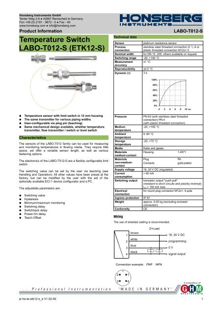
Honsberg Instruments GmbH<br />
Tenter Weg 2-8 ● 42897 Remscheid ● Germany<br />
Fon +49 (0) 2191 - 9672 - 0 ● Fax - 40<br />
www.honsberg.com ● info@honsberg.com<br />
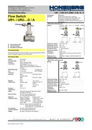
Product In<strong>for</strong>mation<br />
<strong>Temperature</strong> <strong>Switch</strong><br />
<strong>LABO</strong>-T012-S (ETK12-S)<br />
Technical data<br />
<strong>LABO</strong>-T012-S<br />
Sensor<br />
platinum resistance sensor<br />
Process<br />
connection<br />
stainless steel threaded connection G 1 / 2 A or<br />
plastic threaded connection M12x1.5<br />
Nominal width <strong>for</strong> DN 15..300, o<strong>the</strong>rs available on request<br />
<strong>Switch</strong>ing range -20..+100 °C<br />
Measurement ±1 °C<br />
accuracy<br />
Reproducibility ±0.5 °C<br />
Dynamic (τ) 3 s<br />
●<br />
●<br />
●<br />
●<br />
<strong>Temperature</strong> sensor with limit switch in 12 mm housing<br />
The same transmitter <strong>for</strong> various piping widths<br />
User-configurable via plug pin (teaching)<br />
Same mechanical design available, whe<strong>the</strong>r temperature<br />
transmitter, flow transmitter / switch or level switch<br />
Characteristics<br />
The sensors of <strong>the</strong> <strong>LABO</strong>-T012 family can be used <strong>for</strong> measuring<br />
and monitoring temperatures in flowing media. They require little<br />
space, yet offer a variable sensor length, as well as various<br />
fastening options.<br />
The electronics of <strong>the</strong> <strong>LABO</strong>-T012-S are a flexibly configurable limit<br />
switch.<br />
The switching value can be set by <strong>the</strong> user via teaching (see<br />
Handling and Operation). All o<strong>the</strong>r values have been preset at <strong>the</strong><br />
factory, but can be modified by <strong>the</strong> user with <strong>the</strong> aid of <strong>the</strong><br />
optionally available ECI-1 device configurator and a PC.<br />
The adjustable parameters are:<br />
●<br />
●<br />
●<br />
●<br />
●<br />
●<br />
●<br />
<strong>Switch</strong>ing value<br />
Hysteresis<br />
Minimum/maximum monitoring<br />
<strong>Switch</strong>ing delay<br />
<strong>Switch</strong>back delay<br />
Power-On delay<br />
Teach-Offset<br />
Pressure<br />
Medium<br />
temperature<br />
Ambient<br />
temperature<br />
Storage<br />
temperature<br />
Media<br />
Materials<br />
medium-contact<br />
Materials<br />
non-mediumcontact<br />
Supply voltage<br />
Current<br />
consumption<br />
<strong>Switch</strong>ing output<br />
PN 63 (with stainless steel threaded<br />
connection) PN 4<br />
(with plastic threaded connection)<br />
-20..+100 °C<br />
0..60 °C<br />
-20..+70 °C<br />
fluids and gases<br />
Housing 1.4571<br />
Plug<br />
Contacts<br />
18..30 V DC (regulated)<br />
< 60 mA<br />
PA<br />
gold-plated<br />
transistor output "push-pull"<br />
(resistant to short circuits and polarity reversal)<br />
l out = 100 mA max.<br />
<strong>for</strong> round plug connector M12x1, 4-pole<br />
Electrical<br />
connection<br />
Ingress protection IP 67<br />
Weight<br />
approx. 0.05 kg (excluding screwed<br />
connection)<br />
Con<strong>for</strong>mity CE<br />
Wiring<br />
The use of shielded cabling is recommended.<br />
1<br />
2<br />
3<br />
4<br />
brown<br />
white<br />
blue<br />
black<br />
Z=Load<br />
Z<br />
Z<br />
18..30 V DC<br />
programming<br />
0 V<br />
signal output<br />
Connection example:<br />
PNP<br />
NPN<br />
2<br />
3<br />
1<br />
4<br />
pi-ho-te-etk12-s_e V1.02-00 1
Honsberg Instruments GmbH<br />
Tenter Weg 2-8 ● 42897 Remscheid ● Germany<br />
Fon +49 (0) 2191 - 9672 - 0 ● Fax - 40<br />
www.honsberg.com ● info@honsberg.com<br />
Product In<strong>for</strong>mation<br />
Dimensions<br />
Optional accessories<br />
Weld-on adapter<br />
Crimp screw joint<br />
<strong>LABO</strong>-T012-S<br />
status during <strong>the</strong> teach-in, <strong>the</strong> device can be provided ex-works<br />
with a teach-offset. The teach-offset point is added to <strong>the</strong> currently<br />
measured value be<strong>for</strong>e saving.<br />
Example: The switching value is to be set to 80 °C, because at this<br />
temperature a critical process status is to be notified. However,<br />
only 60 °C can be achieved without danger. In this case, <strong>the</strong> device<br />
would be ordered with a "teach-offset" of +20 °C. At 60 °C in <strong>the</strong><br />
process, a switching value of 80 °C would <strong>the</strong>n be stored during<br />
"teaching".<br />
The <strong>LABO</strong>-T012-S limit switch can be used to monitor minima or<br />
minima or maxima.<br />
With a minimum-switch, falling below <strong>the</strong> limit value causes a<br />
switchover to <strong>the</strong> alarm state. Return to <strong>the</strong> normal state occurs<br />
when <strong>the</strong> limit value plus <strong>the</strong> set hysteresis is once more exceeded.<br />
T<br />
stainless steel<br />
Flange mounting<br />
plastic<br />
Compression fitting<br />
plastic<br />
switchover to <strong>the</strong> alarm state. Return to <strong>the</strong> normal state occurs<br />
when <strong>the</strong> measured value once more falls below <strong>the</strong> limit value<br />
minus <strong>the</strong> set hysteresis.<br />
T<br />
Handling and operation<br />
Installation<br />
W<strong>here</strong>ver possible, <strong>the</strong> sensor<br />
tip should be positioned in <strong>the</strong><br />
middle of <strong>the</strong> pipe. When a<br />
flow is present, it should<br />
impinge onto <strong>the</strong> X, in order to<br />
achieve <strong>the</strong> lowest possible<br />
response time.<br />
Avoid bubbles or deposits on <strong>the</strong> sensor. It is <strong>the</strong>re<strong>for</strong>e best to<br />
install at <strong>the</strong> side. The stainless steel threaded connection is first<br />
tightened by hand, and <strong>the</strong>n by 1 / 4 of a turn, using a spanner. The<br />
connection ring of <strong>the</strong> threaded connection can <strong>the</strong>n no longer be<br />
removed from <strong>the</strong> sensor, and <strong>the</strong> immersion depth can <strong>the</strong>re<strong>for</strong>e<br />
not be changed fur<strong>the</strong>r.<br />
Operation and programming<br />
Marking<br />
Flow<br />
The switching value can be set by <strong>the</strong> user by means of teaching.<br />
For this, proceed as follows:<br />
● The temperature which is to be set is applied to <strong>the</strong> device.<br />
● Apply a pulse of at least 0.5 seconds and max. 2 seconds duration<br />
to pin 2 (e.g. via a bridge to <strong>the</strong> supply voltage or a pulse<br />
from <strong>the</strong> PLC), in order to accept <strong>the</strong> measured value.<br />
● When <strong>the</strong> teaching is complete, pin 2 should be connected to<br />
0 V, so as to prevent unintended programming.<br />
The device has a yellow LED which flashes during <strong>the</strong><br />
programming pulse. During operation, <strong>the</strong> LED serves as a status<br />
display <strong>for</strong> <strong>the</strong> switching output.<br />
In order to avoid <strong>the</strong> need to transit to an undesired operating<br />
x<br />
Max<br />
Max-Hyst<br />
A switchover delay time (t DS) can be applied to <strong>the</strong> switchover to <strong>the</strong><br />
alarm state. Equally, one switch-back delay time (t DR) of several can<br />
be applied to switching back to <strong>the</strong> normal state.<br />
Max<br />
Max-Hyst<br />
T<br />
t DS<br />
t DR<br />
In <strong>the</strong> normal state <strong>the</strong> integrated LED is on, in <strong>the</strong> alarm state it is<br />
off, and this corresponds to its status when <strong>the</strong>re is no supply<br />
voltage.<br />
In <strong>the</strong> non-inverted (standard) model, while in <strong>the</strong> normal state <strong>the</strong><br />
switching output is at <strong>the</strong> level of <strong>the</strong> supply voltage; in <strong>the</strong> alarm<br />
t<br />
t<br />
2 pi-ho-te-etk12-s_e V1.02-00
Honsberg Instruments GmbH<br />
Tenter Weg 2-8 ● 42897 Remscheid ● Germany<br />
Fon +49 (0) 2191 - 9672 - 0 ● Fax - 40<br />
www.honsberg.com ● info@honsberg.com<br />
Product In<strong>for</strong>mation<br />
state it is at 0 V, so that a wire break would also display as an alarm<br />
state at <strong>the</strong> signal receiver. Optionally, an inverted switching output<br />
can also be provided, i.e. in <strong>the</strong> normal state <strong>the</strong> output is at 0 V,<br />
and in <strong>the</strong> alarm state it is at <strong>the</strong> level of <strong>the</strong> supply voltage.<br />
Ordering code<br />
1. 2. 3. 4. 5. 6<br />
<strong>LABO</strong>-T012 - S K1<br />
<strong>LABO</strong>-T012-S<br />
=Option<br />
non-inverted output<br />
inverted output<br />
A Power-On-Delay function (ordered as a separate option) makes it<br />
possible to maintain <strong>the</strong> switching output in <strong>the</strong> normal state <strong>for</strong> a<br />
defined period after application of <strong>the</strong> supply voltage.<br />
t<br />
1. <strong>Switch</strong><br />
S<br />
push-pull switch<br />
(compatible with PNP and NPN)<br />
2. Sensor length L =<br />
100 123 mm<br />
150 173 mm<br />
200 223 mm<br />
3. Connection material<br />
K1 stainless steel 1.4571<br />
4. Programming<br />
N<br />
cannot be programmed (no teaching)<br />
P programmable (teaching possible)<br />
5. <strong>Switch</strong> type<br />
L<br />
minimum-switch<br />
H<br />
maximum-switch<br />
6. Output<br />
O<br />
non-inverted output<br />
I inverted output<br />
Options<br />
<strong>Switch</strong>ing delay period (0.0..99.9 s) . s<br />
(from Normal to Alarm)<br />
<strong>Switch</strong>-back delay period (0.0..99.9 s) . s<br />
(from Alarm to Normal)<br />
Power-On delay period (0..99 s)<br />
s<br />
<strong>Switch</strong>ing output fixed at °C<br />
<strong>Switch</strong>ing hysteresis %<br />
Standard = 2 % of <strong>the</strong> metering range<br />
Teach-offset (-100..+100 °C) °C<br />
Standard = 0 °C<br />
Fur<strong>the</strong>r options available on request.<br />
Accessories<br />
●<br />
●<br />
●<br />
●<br />
●<br />
Screwed connections<br />
Weld-on adapter<br />
Cable/round plug connector (KB...)<br />
see additional in<strong>for</strong>mation “Accessories”<br />
Device configurator ECI-1<br />
Connection cable<br />
pi-ho-te-etk12-s_e V1.02-00 3