Product Information
Product Information
Product Information

Create successful ePaper yourself
Turn your PDF publications into a flip-book with our unique Google optimized e-Paper software.
Honsberg Instruments GmbH<br />
Tenter Weg 2-8 ● 42897 Remscheid ● Germany<br />
Fon +49 (0) 2191 - 9672 - 0 ● Fax - 40<br />
www.honsberg.com ● info@honsberg.com<br />
<strong>Product</strong> <strong>Information</strong><br />
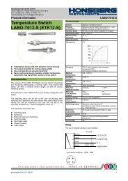
The limit switch can be used to monitor minima or maxima.<br />
Sensors and Instrumentation<br />
With a minimum-switch, falling below the limit value causes a<br />
switchover to the alarm state. Return to the normal state occurs<br />
when the limit value plus the set hysteresis is again exceeded.<br />
T<br />
non-inverted output<br />
t<br />
Min+Hyst<br />
Min<br />
inverted output<br />
With a maximum-switch, exceeding the limit value causes a<br />
switchover to the alarm state. Return to the normal state occurs<br />
when the measured value once more falls below the limit value<br />
minus the set hysteresis.<br />
T<br />
t<br />
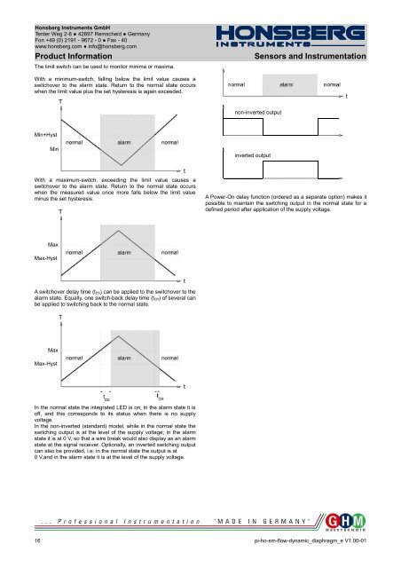
A Power-On delay function (ordered as a separate option) makes it<br />
possible to maintain the switching output in the normal state for a<br />
defined period after application of the supply voltage.<br />
Max<br />
Max-Hyst<br />
A switchover delay time (t DS) can be applied to the switchover to the<br />
alarm state. Equally, one switch-back delay time (t DR) of several can<br />
be applied to switching back to the normal state.<br />
T<br />
t<br />
Max<br />
Max-Hyst<br />
t<br />
In the normal state the integrated LED is on, in the alarm state it is<br />
off, and this corresponds to its status when there is no supply<br />
voltage.<br />
In the non-inverted (standard) model, while in the normal state the<br />
switching output is at the level of the supply voltage; in the alarm<br />
state it is at 0 V, so that a wire break would also display as an alarm<br />
state at the signal receiver. Optionally, an inverted switching output<br />
can also be provided, i.e. in the normal state the output is at<br />
0 V,and in the alarm state it is at the level of the supply voltage.<br />
16 pi-ho-sm-flow-dynamic_diaphragm_e V1.00-01