Product Information
Product Information
Product Information

Create successful ePaper yourself
Turn your PDF publications into a flip-book with our unique Google optimized e-Paper software.
Honsberg Instruments GmbH<br />
Tenter Weg 2-8 ● 42897 Remscheid ● Germany<br />
Fon +49 (0) 2191 - 9672 - 0 ● Fax - 40<br />
www.honsberg.com ● info@honsberg.com<br />
<strong>Product</strong> <strong>Information</strong><br />
Flow Transmitter /<br />
Switch OMNI-XF<br />
Sensors and Instrumentation<br />
diaphragm mean that even severe water hammer causes no<br />
damage. The low number of medium contact parts guarantees<br />
reliable operation and a low tendency to contamination.<br />
There are flanged connection pieces on the inlet and outlet; these<br />
are available in various nominal widths and materials. By removing<br />
the four bolts of the flange connection, it is simple to remove the<br />
measurement unit for servicing, while the connections remain in the<br />
pipework.<br />
The OMNI transducer located on the sensor has a backlit graphics<br />
LCD display which is very easy to read, both in the dark and in<br />
bright sunlight. The graphics display allows the presentation of<br />
measured values and parameters in a clearly understandable form.<br />
●<br />
●<br />
●<br />
●<br />
●<br />
●<br />
●<br />
Universal flow rate sensor with dynamic diaphragm<br />
Analog output, two switching outputs<br />
Clear, easily legible, illuminated LCD display<br />
Modifiable units in the display<br />
Designed for industrial use<br />
Small, compact construction<br />
Simple installation<br />
Characteristics<br />
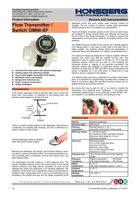
A thin elastic diaphragm made of stainless steel, which covers the<br />
entire flow cross-section, is deflected by the flowing fluid, and<br />
thereby pushes against an arched end stop.<br />
The measured values are displayed to 4 places, together with their<br />
physical unit, which may also be modified by the user. The<br />
electronics have an analog output (4..20 mA or 0..10 V) and two<br />
switching outputs, which can be used as limit switches for<br />
monitoring minima or maxima, or as two-point controllers. The<br />
switching outputs are designed as push-pull drivers, and can<br />
therefore be used both as PNP and NPN outputs. Exceeding limit<br />
values is signalled by a red LED which is visible over a long<br />
distance, and by a cleartext in the display.<br />
The stainless steel case has a hardened non-scratch mineral glass<br />
pane. It is operated by a programming ring fitted with a magnet, so<br />
there is no need to open the operating controls housing, and its<br />
leakproofness is permanently ensured.<br />
By turning the ring to right or left, it is simple to modify the<br />
parameters (e.g. switching point, hysteresis...). To protect from<br />
unintended programming, it can be removed, turned through 180 °<br />
and replaced, or completely removed, thus acting as a key.<br />
End stop<br />
Flow<br />
Diaphragm<br />
Magnet<br />
There is a plastic-coated magnet on the diaphragm. When there is<br />
a deflection, its magnetic field changes, and this is detected by a<br />
sensor outside the area of flow.<br />
Flexible diaphragm made of stainless<br />
steel, with plastic-coated magnet.<br />
Because the diaphragm only bends, and functions without a bearing,<br />
there is almost no frictional effect. The movement therefore occurs<br />
practically free of hysteresis, and the test results have very<br />
good reproducibility.<br />
The diaphragm's low bulk results in a short response time. The<br />
almost complete covering of the flow cross-section in the neutral<br />
position produces very high start-up sensitivity. As soon as the<br />
slightest flow exists, the diaphragm is of necessity deflected. The<br />
evaluation of the entire flow cross-section means that there are no<br />
problems when routing pipes. Run-in and run-out sections are not<br />
necessary. The shaped end stop and the elastic properties of the<br />
Technical data<br />
Sensor<br />
dynamic diaphragm<br />
Nominal width DN 8.0.25<br />
Process<br />
connection<br />
female thread G 1 / 4..G 1,<br />
optionally male thread or hose nozzle<br />
Metering ranges 1..100 l/min (water)<br />
for standard ranges, see table "Ranges",<br />
minimum value range 0.4..6 l/min<br />
optionally available<br />
Accuracy<br />
Standard ranges:<br />
±3 % of the measured value,<br />
minimum 0.25 l/min<br />
Minimum value range:<br />
±3 % of the measured value,<br />
minimum 0.1 l/min<br />
Pressure loss max. 0.5 bar at the end of the metering<br />
range<br />
Pressure<br />
Plastic construction: PN 16 bar<br />
resistance Full metal construction: PN 100 bar<br />
Media<br />
0..70 °C<br />
temperature with high temperature option 0..150 °C<br />
Ambient<br />
0..70 °C<br />
temperature<br />
Storage<br />
-20..+80 °C<br />
temperature<br />
18 pi-ho-sm-flow-dynamic_diaphragm_e V1.00-01