dovetail jig supplementary instruction manual (39887) - Rockler.com
dovetail jig supplementary instruction manual (39887) - Rockler.com
dovetail jig supplementary instruction manual (39887) - Rockler.com

Create successful ePaper yourself
Turn your PDF publications into a flip-book with our unique Google optimized e-Paper software.
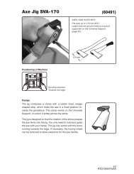
ACUTE ANGLED JOINTS<br />
Fig. 55A<br />
An acute angle joint joins two boards together at an angle less<br />
than 90°. The acute angled joint is very similar in construction to<br />
the the obtuse angled joint and can be used with the obtuse<br />
angled joint to make boxes with angles other than 90°.<br />
SETUP<br />
Joint<br />
Angle<br />
Use the same setup as you would for the obtuse angled joint. Use 180° minus the joint angle for the insert angle<br />
when you make your angled insert or your angled clamping board.<br />
NOTE: If the acute angle and the obtuse angle add up to 180°, use the same setup for both joints.<br />
CUTTING THE TAILS<br />
Step 1 -<br />
Step 2 -<br />
Step 3 -<br />
Step 4 -<br />
Step 5 -<br />
Cut the end of the tail board according to the <strong>instruction</strong>s on the drawing (Fig. 56A). Steep angles or thin<br />
wood will make for a weak joint. Make this cut on a table saw with the blade beveled. Set the miter gauge<br />
at 90° for the first cut and use a tenoning <strong>jig</strong> for the second cut (Fig. 56B).<br />
Clamp the workpiece as you did for the obtuse-angled joint, except face the outside surface of the board<br />
away from the base of the <strong>jig</strong>.<br />
Step 3 is identical to Step 5 in "CUTTING THE TAILS" of the obtuse-angled section.<br />
Set the router bit depth to where the step is in the tail board.<br />
Cut the tails and remove the tail board.<br />
FIRST CUT<br />
SECOND CUT<br />
THICKNESS OF PIN BOARD<br />
THIRD CUT<br />
(IF NECESSARY)<br />
ANGLE BETWEEN BOARDS<br />
OUTSIDE<br />
SURFACE<br />
OF BOARD<br />
INSIDE<br />
SURFACE<br />
OF BOARD<br />
Fig. 56A<br />
Fig. 56B<br />
CUTTING THE PINS<br />
Step 1 -<br />
Step 2 -<br />
Step 3 -<br />
Step 4 -<br />
Cut the end of the pin board according to the <strong>instruction</strong>s on the drawing (Fig. 57A). Steep angles or thin<br />
wood will make for a weak joint. Make this cut on a table saw with the blade beveled, and with the miter<br />
gauge set at 90°.<br />
Clamp the workpiece as you did for the obtuse-angled joint.<br />
Hold the boards together and mark the end of the pin board at the edges of the tails.<br />
The remainder of the steps, including fitting the joint, are identical to the obtuse-angled joint section.<br />
32