dovetail jig supplementary instruction manual (39887) - Rockler.com
dovetail jig supplementary instruction manual (39887) - Rockler.com
dovetail jig supplementary instruction manual (39887) - Rockler.com

Create successful ePaper yourself
Turn your PDF publications into a flip-book with our unique Google optimized e-Paper software.
Note: <strong>Rockler</strong> may not carry all products and/or sizes listed in this vendor's publication<br />
SUPPLEMENTARY<br />
INSTRUCTION<br />
MANUAL<br />
DOVETAIL JIG<br />
MODELS 4210 & 4212<br />
(<strong>39887</strong>)<br />
To learn more about Porter-Cable<br />
visit our website at:<br />
http://www.porter-cable.<strong>com</strong><br />
IMPORTANT<br />
Please make certain that the person who is<br />
to use this equipment carefully reads and<br />
understands these <strong>instruction</strong>s before<br />
starting operations.<br />
The Model and Serial No. plate is located on the main<br />
housing of the tool. Record these numbers in the<br />
spaces below and retain for future reference.<br />
Model No. _____________________________________<br />
Type __________________________________________<br />
Copyright © 2005 Porter-Cable Corporation<br />
Serial No.______________________________________<br />
RTD10000211AA<br />
Part No. A06477 - 02-23-05
TABLE OF CONTENTS<br />
SAFETY GUIDELINES<br />
IMPORTANT SAFETY INSTRUCTIONS<br />
ADDITIONAL SPECIFIC SAFETY RULES<br />
BACKGROUND INFORMATION<br />
OPERATION<br />
MISCELLANEOUS TECHNIQUES<br />
THROUGH-DOVETAILS WITH CLAMPING BOARDS<br />
THROUGH-DOVETAILS WITH UNLIMITED BOARD WIDTH<br />
ALTERNATIVE METHOD - THROUGH-DOVETAILS WITH UNLIMITED BOARD WIDTH<br />
HALF-BLIND DOVETAILS WITH CLAMPING BOARDS<br />
USING A ROUTER TABLE<br />
ALTERNATE ROUTER BITS<br />
HALF-BLIND DOVETAIL TAILBOARDS THICKER THAN 7/8"<br />
MITERED THROUGH-DOVETAILS<br />
THROUGH-DOVETAIL, SKIPPED PIN METHOD<br />
HALF-BLIND DOVETAIL, SKIPPED PIN METHOD<br />
SAW KERF ALLOWANCE METHOD<br />
MULTIPLE SPACER METHOD<br />
END-TO-END JOINTS<br />
DRAWERS WITH DOVETAIL DADOS<br />
WOODEN HINGES<br />
ANGLED JOINTS<br />
ACUTE ANGLED JOINTS<br />
SLANTED SIDE JOINTS<br />
COMPOUND ANGLED JOINTS<br />
INLAYED THROUGH-DOVETAILS<br />
INLAYED HALF-BLIND DOVETAIL JOINTS<br />
INLAYED BOX JOINTS<br />
TABLES OF COMMONLY AVAILABLE ROUTER BIT SIZES<br />
TROUBLESHOOTING<br />
MAINTENANCE<br />
SERVICE<br />
ACCESSORIES<br />
3<br />
3<br />
4<br />
4<br />
5<br />
5<br />
6<br />
8<br />
10<br />
11<br />
13<br />
14<br />
17<br />
18<br />
19<br />
20<br />
22<br />
24<br />
24<br />
25<br />
26<br />
29<br />
32<br />
33<br />
34<br />
37<br />
38<br />
40<br />
41<br />
42<br />
42<br />
42<br />
42<br />
WARRANTY<br />
SERVICE CENTER LOCATIONS<br />
43<br />
Back Cover<br />
2
SAFETY GUIDELINES - DEFINITIONS<br />
This <strong>manual</strong> contains information that is important for you to know and understand. This information relates to protecting<br />
YOUR SAFETY and PREVENTING EQUIPMENT PROBLEMS. To help you recognize this information, we use<br />
the symbols to the left. Please read the <strong>manual</strong> and pay attention to these sections.<br />
Indicates an imminently hazardous situation which, if not avoided, will result in death or serious injury.<br />
Indicates a potentially hazardous situation which, if not avoided, could result in death or serious injury.<br />
Indicates a potentially hazardous situation which, if not avoided, may result in minor or moderate injury.<br />
Used without the safety alert symbol indicates potentially hazardous situation which, if not avoided, may<br />
result in property damage.<br />
IMPORTANT SAFETY INSTRUCTIONS<br />
Read and understand all <strong>instruction</strong>s. Failure to follow all <strong>instruction</strong>s listed below, may<br />
result in electric shock, fire and/or serious personal injury.<br />
SAVE THESE INSTRUCTIONS.<br />
There are certain applications for which this tool was designed. Porter-Cable strongly re<strong>com</strong>mends that this<br />
tool NOT be modified and/or used for any application other than for which it was designed. If you have any questions relative to<br />
its application DO NOT use the tool until you have written Porter-Cable and we have advised you.<br />
Technical Service Manager<br />
Porter-Cable Corporation<br />
4825 Highway 45 North<br />
Jackson, TN 38305<br />
1. KEEP WORK AREA CLEAN. Cluttered areas and benches invite injuries.<br />
2. AVOID DANGEROUS ENVIRONMENT. Don’t expose power tools to rain. Don’t use power tools in damp or wet<br />
locations. Keep area well lit. Avoid chemical or corrosive environment. Do not use tool in presence of flammable<br />
liquids or gases.<br />
3. GUARD AGAINST ELECTRIC SHOCK. Prevent body contact with grounded surfaces. For example: pipes,<br />
radiators, ranges, refrigerator enclosures.<br />
4. KEEP CHILDREN AWAY. Do not let visitors contact tool or extension cord. All visitors should be kept away from<br />
work area.<br />
5. STORE IDLE TOOLS. When not in use, tools should be stored in dry, and high or locked-up place – out of reach<br />
of children.<br />
6. DON’T FORCE TOOL. It will do the job better and safer at the rate for which it was intended.<br />
7. USE RIGHT TOOL. Don’t force small tool or attachment to do the job of a heavy duty tool. Don’t use tool for<br />
purpose not intended – for example – do not use a circular saw for cutting tree limbs or logs.<br />
8. DRESS PROPERLY. Do not wear loose clothing or jewelry. Loose clothing, draw strings and jewelry can be<br />
caught in moving parts. Rubber gloves and non-skid footwear are re<strong>com</strong>mended when working outdoors. Wear<br />
protective hair covering to contain long hair.<br />
9. USE ANSI Z87.1 SAFETY GLASSES. Wear safety glasses or goggles while operating power tools. Also face or<br />
dust mask if operation creates dust. All persons in the area where power tools are being operated should also<br />
wear safety glasses and face or dust mask.<br />
10. DON’T ABUSE CORD. Never carry tool by cord or yank it to disconnect from receptacle. Keep cord from heat,<br />
oil, and sharp edges. Have damaged or worn power cord and strain reliever replaced immediately. DO NOT<br />
ATTEMPT TO REPAIR POWER CORD.<br />
11. SECURE WORK. Use clamps or a vise to hold work. It’s safer than using your hand and it frees both hands to<br />
operate tool.<br />
12. DON’T OVERREACH. Keep proper footing and balance at all times.<br />
13. MAINTAIN TOOLS WITH CARE. Keep tools sharp and clean for better and safer performance. Follow<br />
<strong>instruction</strong>s for lubricating and changing accessories. Inspect tool cords periodically and if damaged, have<br />
repaired by authorized service facility. Inspect extension cords periodically and replace if damaged. Have all<br />
worn, broken or lost parts replaced immediately. Keep handles dry, clean and free from oil and grease.<br />
14. DISCONNECT TOOLS when not in use, before servicing, and when changing accessories such as blades, bits, cutters, etc.<br />
15. REMOVE ADJUSTING KEYS AND WRENCHES. Form habit of checking to see that keys and adjusting<br />
wrenches are removed from the tool before turning it on.<br />
3
16. AVOID UNINTENTIONAL STARTING. Do not carry a plugged-in tool with finger on switch. Be sure switch is off<br />
when plugging in. Keep hands, body and clothing clear of blades, bits, cutters, etc. when plugging in the tool.<br />
17. OUTDOOR USE EXTENSION CORDS. When tool is used outdoors, use only extension cords marked “Suitable<br />
for use with outdoor appliances – store indoors when not in use.” If an extension cord is to be used outdoors it<br />
must be marked with the suffix W-A or w following the cord type designation.<br />
18. STAY ALERT. Watch what you are doing. Use <strong>com</strong>mon sense. Do not operate tool when you are tired or while<br />
under the influence of medication, alcohol or drugs.<br />
19. CHECK DAMAGED PARTS. Before further use of the tool, a guard or other part that is damaged should be<br />
carefully checked to determine that it will operate properly and perform its intended function. Check for alignment<br />
of moving parts, binding of moving parts, breakage of parts, mounting, and any other conditions that may affect<br />
its operation. A guard or other part that is damaged should be properly repaired or replaced by an authorized<br />
service center unless otherwise indicated elsewhere in this <strong>instruction</strong> <strong>manual</strong>. Have defective switches replaced<br />
by authorized service center. Do not use tool if switch does not turn it on and off.<br />
20. WEAR ANSI S3.19 EAR PROTECTION to safeguard against possible hearing loss.<br />
ADDITIONAL SAFETY RULES<br />
FAILURE TO FOLLOW THESE RULES MAY RESULT IN SERIOUS PERSONAL INJURY.<br />
1. READ AND FOLLOW ALL SAFETY INSTRUCTIONS in the <strong>instruction</strong> <strong>manual</strong> supplied with your router.<br />
2. SECURE WORK. Be sure Dovetail Fixture/Jig and work is anchored securely to prevent movement.<br />
3. BE SURE CORD SET IS FREE and will not hang up during routing operations.<br />
4. KEEP HANDS CLEAR of cutter when motor is running to prevent personal injury.<br />
5. MAINTAIN FIRM GRIP on router when starting motor to resist starting torque.<br />
6. STAY ALERT and keep cutter free, clear of all foreign objects while motor is running.<br />
7. BE SURE MOTOR HAS COMPLETELY STOPPED before removing router from Dovetail Fixture/Jig and setting<br />
Dovetail Fixture/Jig down between operations.<br />
8. NEVER REMOVE ROUTER MOTOR from router base while template guide and <strong>dovetail</strong> bit are installed. <strong>dovetail</strong><br />
bit may not fit through hole in template guide.<br />
9. TIGHTEN TEMPLATE GUIDE LOCKNUT SECURELY.<br />
10. SOME WOOD CONTAINS PRESERVATIVES WHICH CAN BE TOXIC. Take extra care to prevent inhalation and<br />
skin contact when working with these materials. Request, and follow, any safety information available from your<br />
material supplier.<br />
REPLACEMENT PARTS<br />
When servicing use only identical replacement parts.<br />
BACKGROUND INFORMATION<br />
The details for basic joints are found in the <strong>instruction</strong> <strong>manual</strong> for the 4212 Dovetail Jig, along with information<br />
regarding the use of various router bits and/or templet guides, and will not be repeated in this supplemental <strong>manual</strong>.<br />
The purpose of this document is to provide you with an advanced knowledge of the <strong>jig</strong> and to promote that<br />
knowledge, along with your creativity, to produce beautiful woodworking projects that can stand the test of time.<br />
4
OPERATION<br />
MISCELLANEOUS TECHNIQUES<br />
Using these techniques can simplify your <strong>dovetail</strong>ing projects.<br />
USE A DEAD-BLOW HAMMER<br />
Use a plastic dead-blow hammer to join your workpieces together to help prevent the marring of wood (Fig. 1A).<br />
CHAMFER THE TAIL EDGES<br />
Chamfering the inner tail edges can make the joints go together easier and may prevent damage to the pins (Fig.<br />
1B). Make the chamfers with a file or a chisel. Since the chamfers are located on the inside of the joint, they will be<br />
invisible.<br />
Fig. 1A<br />
Fig. 1B<br />
ALTERNATE THROUGH DOVETAIL AND BOX JOINT BIT DEPTH SETTING<br />
This method of setting your router bit depth on through <strong>dovetail</strong>s or box joints is very accurate for creating pins or<br />
tails that are flush, and is especially good for inlay work. Use a board that is the same thickness as your workpiece<br />
to be joined and draw a line.<br />
Fig. 2A<br />
Fig. 2B<br />
Set the router on the template and lower the router bit until it reaches the line. Make sure that the scrap material<br />
used in the horizontal position to support the template is at least as thick as the router bit depth-of-cut.<br />
STOP NUT FOR BRASS ADJUSTMENT KNOB<br />
A<br />
If using the same setup repeatedly, you can use a 3/8"-16 nut (A)<br />
Fig. 3A (not supplied) to keep the brass adjustment knobs from<br />
moving.<br />
Fig. 3A<br />
5
TEMPLATES MOUNTED TO CLAMPING BOARDS<br />
You can mount the <strong>jig</strong> templates to clamping boards and take the templates to the workpiece to make the joint. The<br />
benefits of this operation are:<br />
1. You can maneuver a mounted template onto a large workpiece easier than clamping a large workpiece to the<br />
<strong>jig</strong>. This process allows you to join boards wider than 12" by routing a part of the joint, sliding the mounted<br />
template just past the original cut, and routing the remainder of the joint.<br />
Fig. 4A<br />
Fig. 4B<br />
Fig. 4C<br />
2. By using the clamping boards, you can rout boards that<br />
are too short to clamp in the <strong>jig</strong> base, allowing you to<br />
<strong>dovetail</strong> small decorative boxes.<br />
3. You can make half-blind joints in thicker wood than the <strong>jig</strong> can handle.<br />
4. You can make steeply-angled joints with the clamping boards.<br />
5. You can make joints using a router table by inverting the mounted templates.<br />
THROUGH-DOVETAILS WITH CLAMPING BOARDS<br />
You can use both the normal through-<strong>dovetail</strong> template (included with the 4212 Jig and the 4213 Accessory Kit),<br />
and the miniature through-<strong>dovetail</strong> template (included with the 4215 Accessory Kit) with a clamping board.<br />
NOTE: You can modify these clamping board methods to make box joints.<br />
SETUP<br />
Step 1 -<br />
Step 2 -<br />
Step 3 -<br />
Step 4 -<br />
Step 5 -<br />
Make a clamping board 2" x 3" x 19". Make sure<br />
that all four sides are square (You may need to<br />
glue thinner sections of wood together and<br />
plane them to make the 2" board).<br />
Drill the pilot holes for #10 screws on the face of<br />
the board as indicated in the drawing (Fig. 6A).<br />
Remove the brackets from the template (Fig.<br />
6B).<br />
Align the lines of the template with the edges of<br />
the clamping board. You should be able to see<br />
the pilot holes in the elongated slot of the<br />
template Fig. 6C).<br />
Drive two #10 wood screws through the<br />
elongated slots of the template into the<br />
clamping board (Fig. 6D).<br />
DRILL PILOT HOLES<br />
FOR #10 WOOD SCREWS<br />
19 "<br />
WOOD GRAIN<br />
13 "<br />
3 "<br />
1 "<br />
Fig. 6A<br />
2 "<br />
3 "<br />
6
Fig. 6B Fig. 6C Fig. 6D<br />
CUTTING THE TAILS<br />
Step 1 -<br />
Step 2 -<br />
Step 3 -<br />
Step 4 -<br />
Step 5 -<br />
Step 6 -<br />
Clamp the tail board with the outside surface facing away from the clamping board (Fig. 7A). Align the tail<br />
board, using the <strong>instruction</strong>s in your basic <strong>manual</strong> in the section “OPERATION”. Look under<br />
“POSITIONING THE WOOD”, STEP 4.<br />
This step is optional. Clamp stop blocks to the clamping board for rapid setups of repeated cuts.<br />
Use a small square and a pencil to draw a line along the bottom of the clamping board (Fig. 7B). Align the<br />
line with an edge of the tail board. (This line will be used to set up the pin board).<br />
Use the width of the pinboard to mark the depth of the router bit on the tailboard (Fig. 7C).<br />
DISCONNECT THE TOOL FROM THE POWER SOURCE.<br />
Set the router bit depth, using the pencil mark from STEP 4.<br />
Connect your router to the power source and cut the tails (Fig. 7D).<br />
Fig. 7A<br />
Fig. 7B<br />
Fig. 7C<br />
Fig. 7D<br />
CUTTING THE PINS<br />
Step 1 -<br />
Step 2 -<br />
Step 3 -<br />
Step 4 -<br />
Step 5 -<br />
Step 6 -<br />
Clamp the pin board with the outside surface facing away from the clamping board (Fig. 8A). Align the<br />
edge of the pin board with the line drawn in STEP 3 of “CUTTING THE TAILS”.<br />
This step is optional. Clamp stop blocks to the clamping board for rapid setups of repeated cuts.<br />
Use the width of the tail board to make a pencil mark on the pin board for the depth of the router bit.<br />
DISCONNECT THE TOOL FROM THE POWER SOURCE.<br />
Set the router bit depth, using the pencil mark from STEP 3.<br />
Connect your router to the power source and cut the pins (Fig. 8C).<br />
Remove the pin board and check the fit with the tail board (Fig. 8D).<br />
7
Fig. 8A<br />
Fig. 8B<br />
Fig. 8C<br />
Fig. 8D<br />
FITTING THE JOINT<br />
Step 1 -<br />
Step 2 -<br />
Step 3 -<br />
Step 4 -<br />
Step 5-<br />
Step 6 -<br />
Orient the template so that the “PINS” side is<br />
facing you (Fig. 9A).<br />
Loosen the two #10 screws.<br />
If the joint is too loose, move the template<br />
toward you slightly.<br />
If the joint is too tight, move the template away<br />
from you slightly.<br />
Tighten the screws loosened in STEP 2.<br />
Cut the pin board again and check for fit.<br />
Fig. 9A<br />
THROUGH-DOVETAILS WITH UNLIMITED BOARD WIDTH<br />
You can cut <strong>dovetail</strong>s in boards wider than the templates mounted on clamping boards by cutting the first part of<br />
the joint, sliding the templet down the workpiece, and cutting the rest of the joint.<br />
NOTE: Be<strong>com</strong>e familiar with the procedure for cutting through-<strong>dovetail</strong>s with a template on a clamping board before<br />
attempting working with unlimited board width.<br />
SETUP<br />
Remove the half-blind depth bracket. Other than that, the setup is identical to the previous setup.<br />
8
CUTTING THE TAILS<br />
Step 1 - Clamp the tail board with the outside surface facing away from the clamping board (Fig. 10A).<br />
Step 2 - If the board is a width in 1" increments, (12", 13", etc.), center the edge of the board exactly between the<br />
two fingers of the template farthest to the left (Fig. 10B).<br />
Step 3 - If the board is not in 1" increments, take the fraction of an inch that is greater than 1" and divide it by two.<br />
Then move the tailboard to the left of the center of the fingers by that amount (Fig. 10C). EXAMPLE: IF the<br />
board width is 16-1/2", take the 1/2", divide it by two. You would then move the tail board to the left of the<br />
center of the fingers by 1/4" and clamp it in place.<br />
Step 4 - Use a piece of wood the same thickness as the pin board to mark the router bit depth.<br />
DISCONNECT THE TOOL FROM THE POWER SOURCE.<br />
Step 5 - Set the router bit depth, using the pencil mark from STEP 4.<br />
Step 6 - Connect your router to the power source and cut the pins as far as the template will allow.<br />
Fig.10A<br />
Fig. 10B<br />
Fig. 10C<br />
Step 7 -<br />
Step 8 -<br />
Unclamp the templet, slide it down, and center the last cut<br />
between the two straight fingers and reclamp (Fig. 10D).<br />
Repeat STEPS 6 and 7 until the pins are cut across the entire<br />
board.<br />
CUTTING THE PINS<br />
Fig. 10D<br />
Step 1 -<br />
Step 2 -<br />
Step 3 -<br />
Step 4 -<br />
Step 5 -<br />
Step 6 -<br />
Clamp the pin board with the outside surface facing away from the clamping board.<br />
If the board is a width in 1" increments, (12", 13", etc.), center the edge of the board exactly in line with the<br />
finger of the template farthest to the left (Fig. 11A).<br />
If the board is not in 1" increments, take the fraction of an inch that is greater than 1" and divide it by two.<br />
Then move the pin board to the left of center of the fingers by that amount. EXAMPLE: IF the board width<br />
is 16-1/2", take the 1/2", divide it by two. You would then move the tail board to the left of the leftmost<br />
finger by 1/4" and clamp it in place (Fig. 11B).<br />
Use a piece of wood the same thickness as the pin board to mark the router bit depth.<br />
DISCONNECT THE TOOL FROM THE POWER SOURCE.<br />
Set the router bit depth, using the pencil mark from STEP 4.<br />
Connect your router to the power source and cut the pins as far as the template will allow.<br />
Fig. 11A<br />
Fig. 11B<br />
9
Step 7 -<br />
Step 8 -<br />
Step 9 -<br />
Unclamp the templet, slide it down, and center the last cut between the two angled fingers and reclamp<br />
(Fig. 11D).<br />
Repeat STEPS 6 and 7 until the pins are cut across the entire board.<br />
Remove the pin board and check the fit with the tailboard.<br />
FITTING THE JOINT<br />
Fitting the joint is identical to the previous section (Fig. 12A).<br />
Fig. 11D<br />
Fig. 12A<br />
ALTERNATE METHOD<br />
THROUGH-DOVETAILS WITH UNLIMITED BOARD WIDTH<br />
This alternate method may be more accurate for correctly cutting the tail and pin boards.<br />
Step 1 -<br />
Step 2 -<br />
Step 3 -<br />
Step 4 -<br />
Step 5 -<br />
Clamp the tail and pin boards together with a 2" wide block (Fig. 13A).<br />
Use a square to align an edge of the tail and pin boards (Fig. 13B).<br />
Cut the pins and the tails as far as the template will allow (Fig. 13C).<br />
Slide the template, aligning the last cut in between the fingers of the template (Fig. 13D).<br />
Repeat STEPS 3 and 4 until both boards are <strong>com</strong>pletely cut.<br />
Fig. 13A<br />
Fig. 13B<br />
Fig. 13C<br />
Fig. 13D<br />
10
HALF-BLIND DOVETAILS WITH CLAMPING BOARDS<br />
You can mount your half-blind template that <strong>com</strong>es with the 4210 and 4212 <strong>jig</strong>s and the 4211 accessory kit to a<br />
board. This method, however, limits your workpiece width capacity to 8".<br />
SETUP<br />
Items needed to setup for the half-blind <strong>dovetail</strong>s:<br />
1. Wood to make the clamping board parts<br />
2. Clamps<br />
3. 2" #10 wood screws (2)<br />
4. 1/4-20 threaded T-nut<br />
5. 1/4-20 x 4" bolt<br />
6. 1/4" washer<br />
NOTE: These <strong>instruction</strong>s can be modified for making halfblind<br />
<strong>dovetail</strong>s with the through <strong>dovetail</strong> template and for<br />
the miniature <strong>dovetail</strong> template (See the section “HALF-<br />
BLIND DOVETAILS WITH TAIL BOARDS THICKER THAN<br />
7/8"). Fig. 14A<br />
Step 1 -<br />
Step 2 -<br />
Make a main clamping board 1-1/2" x 3-1/4" x 16". Square all of the sides. Make a mortise<br />
through the board and drill pilot holes for #10 wood screws (Fig. 15A).<br />
NOTE: Threaded inserts and #10 flathead machine screws can be used in place of the #10<br />
wood screws.<br />
Make the offset clamping block. Make a counterbore for the threaded T-nut (Fig. 15B).<br />
NOTE: If your pin board is thinner than 3/4", modify the dimension. You may need to use extra<br />
washers to prevent the bolt from sticking out.<br />
2-1/4<br />
"<br />
2 "<br />
3/8" WIDE MORTISE GOES<br />
THROUGH BLOCK. MORTISE<br />
IS CENTERED ON BLOCK.<br />
Fig. 15A<br />
Fig. 15B<br />
1-1/2<br />
"<br />
DRILL A 1/4 " HOLE<br />
THROUGH THE BLOCK<br />
1 "<br />
WOOD GRAIN<br />
1/2 "<br />
1/2 "<br />
1-1/8 "<br />
13-3/4<br />
"<br />
DRILL PILOT HOLES<br />
FOR #10 WOOD SCREWS<br />
3/4 "<br />
WOOD GRAIN<br />
3-1/4<br />
"<br />
16 "<br />
1-1/2<br />
"<br />
MAKE THIS DIMENSION THE<br />
THICKNESS OF THE PIN BOARD<br />
THAT IS TO BE DOVETAILED<br />
MAKE TWO OF THESE BLOCKS<br />
Fig. 15C<br />
Step 3 -<br />
Insert the threaded nut into the offset clamping<br />
block (Fig. 15C).<br />
11
Fig. 15D<br />
Step 4 -<br />
Step 5 -<br />
Step 6 -<br />
Make the straight clamping block. If the<br />
workpiece is thinner than 3/4", you will need to<br />
modify the dimension (Fig. 15D).<br />
Make two thickness blocks the same<br />
thickness as the pin board. Drill a hole big<br />
enough for the wood screw to go through (Fig.<br />
15E).<br />
Assemble the board-mounted half-blind<br />
template (Fig. 15F).<br />
NOTE: You will not need to remove the halfblind<br />
depth bracket.<br />
1-1/2 "<br />
1-1/2 "<br />
5 "<br />
3/4 " (IF THE PIN BOARD IS LESS THAN 3/4" THICK,<br />
THEN REDUCE THIS DIMENSION ACCORDINGLY)<br />
WOOD GRAIN<br />
1-1/2<br />
"<br />
1-1/2<br />
"<br />
1-1/2<br />
"<br />
Fig. 15E<br />
Fig. 15F<br />
2" LONG #10 WOOD SCREWS<br />
DRILL A 1/4 " HOLE<br />
THROUGH THE BLOCK<br />
1 "<br />
WOOD GRAIN<br />
1/2 "<br />
HALF-BLIND TEMPLATE<br />
1/4" T-NUT<br />
THICKNESS<br />
BLOCKS<br />
OFFSET CLAMPING BLOCK<br />
3/4 "<br />
STRAIGHT CLAMPING BLOCK<br />
MAIN CLAMPING BOARD<br />
1/4" WASHER<br />
MAKE THIS DIMENSION THE<br />
THICKNESS OF THE PIN BOARD<br />
THAT IS TO BE DOVETAILED<br />
MAKE TWO OF THESE BLOCKS<br />
4" LONG 1/4-20 BOLT<br />
CUTTING THE JOINT<br />
Step 1 -<br />
Step 2 -<br />
Step 3 -<br />
Clamp the tail board (drawer side) to the main clamping board with the outside surface facing the board<br />
(Fig. 16A).<br />
Move the offset clamping block to the right until it touches the tail board (Fig. 16B). Tighten the 1/4-20 x<br />
4" bolt that holds the offset clamping block.<br />
Insert the pin board (drawer front) flush against the tail board and the offset clamping block (Fig. 16C).<br />
Fig. 16A<br />
Fig. 16B<br />
Fig. 16C<br />
12
Step 4 -<br />
Step 5 -<br />
Step 6 -<br />
Step 7 -<br />
Step 8 -<br />
Slide the straight clamping block to the left so that it contacts the pin board (Fig. 16D). Hook the straight<br />
clamping block over the front and back of the main clamping board.<br />
Secure the pin board by clamping it between the offset and straight clamping blocks (Fig. 16E).<br />
Loosen the #10 wood screws, align the template lines with the line where the pin board and tail board<br />
meet, and retighten the #10 wood screws (Fig. 16F).<br />
DISCONNECT THE TOOL FROM THE POWER SOURCE.<br />
Set the router bit depth, using the bit depth guide.<br />
Cut the joint. Fitting the joint is identical to a standard half-blind <strong>dovetail</strong>.<br />
NOTE: You can cut the pin and tail board separately, if you prefer.<br />
Fig. 16D<br />
Fig. 16E<br />
Fig. 16F<br />
USING A ROUTER TABLE<br />
You can use board-mounted templates with your router table. However,<br />
the templates must be inverted. Similarly, invert all operations (setting the<br />
router bit, etc.).<br />
Fig. 17A<br />
Use protective handles to keep your hands away from the router bit. Grip the handles only on the<br />
opposite side of the workpiece.<br />
12 "<br />
5 "<br />
2 "<br />
Make the protective handles using the dimensions in the<br />
drawing (Fig. 17B). Round over the ends of the handles<br />
so that they are <strong>com</strong>fortable in your hands.<br />
1/2 "<br />
1 "<br />
RADIUS 3/4 "<br />
1-1/2<br />
"<br />
2 "<br />
1 "<br />
MAKE FROM 3/4" STOCK<br />
1/2 "<br />
DRILL HOLES FOR SCREWS<br />
ROUND OVER EDGES<br />
Fig. 17B<br />
13
ALTERNATE ROUTER BITS<br />
You are not limited to using the router bits supplied with your <strong>jig</strong>. Other router bits can be used to produce a different<br />
look or to work with thicker woods. Using alternate bits can help you produce more advanced joints (inlayed<br />
<strong>dovetail</strong>s, etc.). Since 1/2" shank bits are stronger and are much less prone to deflection than the 1/4" shank bits,<br />
we re<strong>com</strong>mend that you use the 1/2" shank bits with the 4210 and 4212 <strong>dovetail</strong> <strong>jig</strong>s, and with the 4211 and 4213<br />
accessory kits.<br />
THROUGH-DOVETAIL BITS<br />
If you choose to purchase alternate through-<strong>dovetail</strong> bits, keep in mind the following:<br />
1. The <strong>dovetail</strong> bit must have a 7° angle. This angle matches the tapered fingers used to guide the straight bit.<br />
2. The sum of the diameters of the <strong>dovetail</strong> and straight bits must equal 15/16". For example, a 5/8" <strong>dovetail</strong> bit<br />
must have a 5/16" straight bit - the sum of both equalling 15/16".<br />
3. The length of the cutter determines the maximum thickness of wood that can be cut. The length of the cutter<br />
on the <strong>dovetail</strong> bit is the maximum thickness of the pin board. The length of the cutter on the straight bit is the<br />
maximum thickness of the tail board. If your bits have 1" cutters, you can make through-<strong>dovetail</strong>s with 1" thick<br />
boards.<br />
4. Purchase bits that will not cut into the template guides. The template guide used with the <strong>dovetail</strong> bit has an<br />
inside diameter of 21/32". Use bits that will fit into this dimension. Some larger bits might work, but with<br />
minimal depth (Fig. 18A).<br />
5. The inside diameter of the template guide used with the straight bit is 17/32". Use straight bits that are smaller<br />
than that dimension.<br />
DOVETAIL BIT<br />
TEMPLET GUIDE<br />
ROUTER SUB BASE<br />
21/32"<br />
DOVETAIL BIT DIAMETER<br />
THERE IS A MINIMUM DEPTH OF CUT<br />
WHEN THE DIAMETER OF THE ROUTER<br />
BIT IS GREATER THAN THE INSIDE<br />
DIAMETER OF THE TEMPLET GUIDE<br />
Fig. 18A<br />
THROUGH-DOVETAIL BIT COMBINATIONS (READILY AVAILABLE)<br />
DOVETAIL BIT DIAMETER<br />
3/4"<br />
5/8"<br />
9/16"<br />
17/32"<br />
STRAIGHT BIT DIAMETER<br />
3/16"<br />
5/16"<br />
3/8"<br />
13/32"<br />
HALF-BLIND DOVETAIL BITS<br />
DOVETAIL BIT<br />
TEMPLET GUIDE<br />
The difference in using alternate bits and standard<br />
bits in making half-blind <strong>dovetail</strong>s is in the depth-ofcut.<br />
ROUTER SUB BASE<br />
WOOD FOR HALF-BLIND JOINT<br />
HALF-BLIND TEMPLET<br />
DEPTH OF CUT FOR A HALF-BLIND JOINT<br />
Fig. 19A<br />
14
Some items to consider when purchasing alternate bits for half-blind <strong>dovetail</strong>s are:<br />
1. A shallow angle of the bit requires a deeper cut. A steeper angle requires a shallower cut.<br />
2. The diameter of the bit should be slightly greater than 1/2". The greater the diameter, the deeper the cut.<br />
3. The bit should have a cutting length at least as long as the cutting depth.<br />
NOTE: When using alternate bits, ensure that the pin board (drawer front) is thicker than the depth of cut.<br />
NOTE: When using alternate bits, ensure that the bit will not cut into the base of the <strong>jig</strong>. For deep cuts, take out<br />
most of the material with a straight bit, then follow up with the half-blind <strong>dovetail</strong> bit.<br />
HALF-BLIND DOVETAIL BIT (READILY AVAILABLE)<br />
DOVETAIL BIT<br />
APP. DEPTH OF CUT<br />
17/32", 7°<br />
17/32", 14°<br />
9/16", 7°<br />
5/8", 14°<br />
13/32"<br />
3/16"<br />
3/4"<br />
9/16"<br />
HALF-BLIND DOVETAIL BITS WITH THE TAILS AND PINS CUT SEPARATELY<br />
Using two different-sized <strong>dovetail</strong> bits to make half-blind <strong>dovetail</strong>s<br />
requires separate cuts, similar to cutting the rabbeted half-blind<br />
<strong>dovetail</strong>. This method provides a more hand-cut look and is an<br />
important step in creating inlayed half-blind <strong>dovetail</strong>s.<br />
Some items to consider:<br />
Fig. 20A<br />
1. The two bits must have the same angle.<br />
2. A shallower angle requires a deeper cut, while a steeper angle requires a shallower cut.<br />
3. When the diameters of the two bits are added together, the sum must be slightly greater than 1". The closer<br />
the sum is to 1", the shallower the depth of cut will be. The larger the sum, the deeper the cut.<br />
BIT COMBINATIONS FOR SEPARATE HALF-BLIND CUTS (READILY AVAILABLE)<br />
LARGER BIT<br />
3/4", 14°<br />
5/8", 14°<br />
5/8", 7°<br />
5/8", 7°<br />
9/16", 7°<br />
SMALLER BIT<br />
1/2" 14°<br />
1/2" 14°<br />
17/32",7°<br />
9/16", 7°<br />
17/32", 7°<br />
APPROX. DEPTH-OF-CUT<br />
9/16"<br />
3/8"<br />
7/8"<br />
1"<br />
5/8"<br />
SETUP<br />
The only difference between cutting this joint and cutting the<br />
standard half-blind is the use of two router bits. If you use one<br />
router, you will have to set the depth-of-cut for each router bit. You<br />
can make a simple depth guide as illustrated in Fig. 21A.<br />
If you have two routers, you will not have to go through the process<br />
of changing the bit each time you make a different cut. This method<br />
requires, however, two 3/4" OD template guides and two template<br />
guide locknuts, available from Porter-Cable.<br />
Fig. 21A<br />
15
CUTTING THE TAILS<br />
Cut the tail board (drawer side) similar to cutting the rabbeted half-blind <strong>dovetail</strong>, but remove the spacer and move<br />
the left offset guide directly against the tail board.<br />
NOTE: Support the template with a scrap workpiece thick enough to prevent the cutter from contacting the base.<br />
CUTTING THE PINS<br />
Cut the pin board (drawer front) similar to cutting the rabbeted half-blind <strong>dovetail</strong>. (If you use the alternate method<br />
of aligning the pin board with secondary board. Make sure the secondary board does not have a rabbet).<br />
NOTE: Ensure that the pin board (drawer front) is thicker than the depth of cut to prevent the cutter from contacting<br />
the base.<br />
FITTING THE JOINT<br />
Fit the joint the same as you would a standard rabbeted half-blind <strong>dovetail</strong>.<br />
NOTE: If a change in depth-of-cut is required, change it on both bits.<br />
BOX JOINT BITS<br />
You can make box joints with different diameter router bits for the two workpieces. The process is identical to<br />
making standard box joints except that you will need to change the bit for the second board. Two routers will make<br />
this job easier. However, this two-router method will require two 3/4" OD template guides and two template guide<br />
lock nuts, available from Porter-Cable.<br />
In selecting straight bits for these modified box joints, keep in mind the following:<br />
1. The sum of the diameters of the two straight bits must equal 1".<br />
2, The length of the bit used to cut the first board determines the maximum thickness of the second board.<br />
(Example: if a 3/8" diameter bit used on the first board has a 1/2" long cutter, the maximum thickness of the<br />
second board would be 1/2").<br />
BOX JOINT BITS (READILY AVAILABLE)<br />
LARGER STRAIGHT BIT<br />
1/2"<br />
9/16"<br />
5/8"<br />
SMALLER STRAIGHT BIT<br />
1/2"<br />
7/16"<br />
3/8"<br />
DOVETAIL DADO BITS<br />
Any <strong>dovetail</strong> bit can be used to make <strong>dovetail</strong> dados (sliding <strong>dovetail</strong>s) as long as the bit does not cut into the<br />
template guide or the base of the <strong>jig</strong>. The process is identical to that of the standard <strong>dovetail</strong> dado. Also, you can<br />
use template guides smaller than 3/4" OD which will have the effect of making the dado slot wider than the bit<br />
diameter.<br />
NOTE: Any template guide bushing surface must not extend more than 1/4" from the base.<br />
16
DOVETAIL BIT<br />
TEMPLET GUIDE<br />
ROUTER SUB BASE<br />
I.D. OF TEMPLET GUIDE<br />
DOVETAIL BIT DIAMETER<br />
THERE IS A MINIMUM DEPTH OF CUT<br />
WHEN THE DIAMETER OF THE ROUTER<br />
BIT IS GREATER THAN THE INSIDE<br />
DIAMETER OF THE TEMPLET GUIDE<br />
Fig. 22A<br />
Cutting a dado with a templet guide that has an OD smaller than 3/4" requires two passes.<br />
1. Start on the left side. Keep the router toward the back edge of the dado slot, and cut to the right until you have<br />
<strong>com</strong>pleted the cut.<br />
2. Start on the right side. Keep the router towards the front edge of the dado slot, and cut to the left until you<br />
<strong>com</strong>plete the cut.<br />
3. Leave the router in the dado slot until the bit stops spinning.<br />
NOTE: For deep cuts, use a straight bit first.<br />
NOTE: Cut the tenon just as you would a standard tenon.<br />
1/4" Maximum<br />
Fig. 23A<br />
Fig. 23B<br />
HALF-BLIND DOVETAILS WITH TAIL BOARDS THICKER THAN 7/8"<br />
For tail boards thicker than 7/8", you can use the template normally used for through <strong>dovetail</strong>s (instead of that used<br />
for half-blind <strong>dovetail</strong>s) to provide deeper pins and tails (Fig. 24A).<br />
The procedure is the same as that for a normal half-blind <strong>dovetail</strong>.<br />
NOTE: Use the “half-blind” line for aligning the template.<br />
Fig. 24A<br />
Fig. 24B<br />
With the wood clamped to the base of the <strong>jig</strong>, the maximum thickness will be 1-1/8". By using a templet mounted<br />
to a clamping board, you can use much thicker wood, producing a strong joint.<br />
17
MITERED THROUGH-DOVETAIL<br />
You can make a through-<strong>dovetail</strong> with a mitered edge, creating<br />
a molded edge that goes the whole way to the joint. This joint is<br />
very attractive on serving trays or decorative boxes without lids.<br />
CUTTING THE TAILS<br />
Fig. 25A<br />
NOTE: Depending on the depth of the molded edge, you may want to make the boards slightly wider to account for<br />
the molded depth. If so, mount the tail board so that the mitered edge will end with the thicker half-pin. With the<br />
offset guide set against the tail board, the pin board will automatically be cut correctly.<br />
Cut the tails as you would a standard through-<strong>dovetail</strong>, except<br />
do not make the tail cut on the edge from the proposed miter.<br />
CUTTING THE PINS<br />
Fig. 26A<br />
Step 1 -<br />
Step 2 -<br />
Step 3 -<br />
Step 4 -<br />
Step 5 -<br />
Step 6 -<br />
Cut all the pins normally.<br />
Remove the template, turn it horizontally so that the straight fingers are facing you.<br />
Adjust the board so that the edge where the miter will be cut is to the left.<br />
Adjust the board so that only the triangular part of the half-pin will be cut off with the router and straight<br />
bit, leaving a squared-off pin (Figs. 27A and 27B).<br />
For repeated cuts, slide the left offset guide until it touches the pin board and secure it.<br />
Cut the triangular area off (Fig. 27C).<br />
Fig. 27A<br />
Fig. 27B<br />
Fig. 27C<br />
MITERING THE PINS<br />
Step 1 -<br />
Step 2 -<br />
On the inside surface, use a square and pencil to draw a line from the base of the pins to the edge<br />
where the miter will be cut (Fig. 28A).<br />
Use a table saw with the miter gauge set to 45° to miter the squared-off half pin (Figs. 28B and<br />
28C).<br />
18
Fig. 28A<br />
Fig. 28B<br />
Fig. 28C<br />
MITERING THE TAILS<br />
Step 1 -<br />
Step 2 -<br />
Step 3 -<br />
On the inside surface, use a square and pencil to draw a line from the base of the tails to the edge where<br />
the miter will be cut (Fig. 29A).<br />
Set the table saw blade so that the height of cut of the saw blade is the same as the thickness of the<br />
mitered half-pin.<br />
Use a table saw with the miter gauge set to 45° to miter the tails. You will need to make several passes<br />
to cut out the material (Fig. 29B).<br />
NOTE: A dado head could be used to make this cut in one pass.<br />
Fig. 29A Fig. 29B Fig. 29C<br />
FITTING THE JOINT<br />
You may need to trim the miter cuts by hand for a good fit. Files, chisels, shoulder planes, and rabbet planes work<br />
well. Otherwise, adjust the tightness of the joint the same as you would for a normal through <strong>dovetail</strong>.<br />
THROUGH-DOVETAIL, SKIPPED-PIN METHOD<br />
This method is very similar to cutting standard through- <strong>dovetail</strong>s (Fig. 30A).<br />
CUTTING THE TAILS<br />
Cut the tails as normal, except do not cut into the areas where you do not want a pin to appear.<br />
Fig. 30A<br />
Fig. 31A<br />
19
CUTTING THE PINS<br />
Step 1 -<br />
Step 2 -<br />
Step 3 -<br />
Step 4 -<br />
Step 5 -<br />
Step 6 -<br />
Hold the pin board against the tail board and mark the edges of the tails on the end of the pin board<br />
(Fig. 32A).<br />
Shade in the areas on the end of the pin board where the tails will be (Fig. 32B).<br />
Cut all the pins (Fig. 32C).<br />
Slide the pin board to the right 1/4" (Fig. 32D).<br />
Cut in between the fingers of the template to cut only in the shaded area (A) Fig. 32D.<br />
Repeat STEPS 4 and 5 until all of the material between the pins has been removed.<br />
Fig. 32A<br />
Fig. 32B<br />
A<br />
Fig. 32C<br />
Fig. 32D<br />
FITTING THE JOINT<br />
Fig. 32D<br />
Fit the joint the same as you would a standard through <strong>dovetail</strong>.<br />
HALF-BLIND DOVETAIL, SKIPPED PIN METHOD<br />
This method is similar to making standard half-blind <strong>dovetail</strong>s,<br />
except that the tails and pins are cut separately.<br />
Cut the tails first. Use a scrap workpiece (thick enough to<br />
prevent contact with the base of the <strong>jig</strong>) to support the<br />
template.<br />
Fig. 33A<br />
20
Step 1 -<br />
Step 2 -<br />
Step 3 -<br />
Step 4 -<br />
Step 5 -<br />
Step 6 -<br />
Step 7 -<br />
Step 8 -<br />
Make a climb cut from right to left.<br />
Cut only between the fingers where you want the pins to be (Fig. 34A).<br />
Use the router to round over the ends of the cuts (Fig. 34B).<br />
The joint will hide any accidental excess material cut (A) Fig. 34C.<br />
Use a pencil to mark the location of the ends of the templet fingers on the wood (Fig. 34D).<br />
Remove the templet. Install the half-blind templet so that its straight edge is facing you.<br />
Adjust the template back and forth to align the edge of the template with the marks on the wood(B) Fig.<br />
34E.<br />
Make a cut from left to right removing the remainder of the excess material (Fig. 34F).<br />
A<br />
Fig. 34A<br />
Fig. 34B<br />
Fig. 34C<br />
B<br />
Fig. 34D Fig. 34E Fig. 34F<br />
CUTTING THE PINS<br />
Step 1 -<br />
Step 2 -<br />
Step 3 -<br />
Cut the tails. Clean out all of the areas between the fingers(Fig. 35A).<br />
Use a pencil to mark the location of the half-circle between the fingers of the templates (C) Fig. 35B.<br />
Remove the pin board and hold it next to the tail board.<br />
C<br />
Fig. 35A Fig. 35B Fig. 35C<br />
21
Step 4 -<br />
Step 5 -<br />
Step 6 -<br />
Step 7 -<br />
Step 8 -<br />
Step 9 -<br />
Step 10 -<br />
Shade the pins that will be removed (Fig. 35C).<br />
Place the pin board back in the <strong>jig</strong>.<br />
Install the half-blind template so that its straight edge faces you.<br />
Adjust the pin board so that the marks align with the straight edge of the templet (D) Fig. 35D.<br />
Make the cuts with the router to remove the shaded pins (Fig. 35E).<br />
Remove all excess material.<br />
If you remove a bit more material than necessary, remember that it will be hidden in the joint (E) Fig. 35F.<br />
E<br />
D<br />
Fig. 35D<br />
Fig. 35E<br />
Fig. 35F<br />
FITTING THE JOINT<br />
Fit the joint the same as you would the half-blind <strong>dovetail</strong>.<br />
SAW KERF ALLOWANCE METHOD<br />
An effective way to match the grain in a decorative box is to make the box from one piece of wood and then cut<br />
the lid with a table saw. However, if the <strong>dovetail</strong>s are evenly spaced, they may be unattractive because the saw kerf<br />
removed needed material.<br />
Fig. 37A<br />
Fig. 37B<br />
NOTE: For this method, you will need a spacer block equal to the thickness of the saw kerf, typically 1/8" on a<br />
standard saw blade. Also, make the boards wider than the final size of the box by the same thickness.<br />
NOTE: This method is very similar to making standard through-<strong>dovetail</strong>s.<br />
22
CUTTING THE TAILS<br />
Step 1 -<br />
Step 2 -<br />
Step 3 -<br />
Step 4 -<br />
Step 5 -<br />
Center and clamp the tailboard as normal, but use the spacer on the left side of the board (A) Fig.<br />
38A. (The spacer will cause the board to move slightly off center to the right).<br />
Mark between the two fingers on the template where you want the kerf to be (B) Fig. 38B.<br />
Cut the tails from the far left to the right. Stop at the mark (Fig. 38C).<br />
Remove the spacer and slide the tail board to the left.<br />
Cut the rest of the tails, starting with the tail that has the mark (Fig. 38D).<br />
A<br />
B<br />
Fig. 38A<br />
Fig. 38B<br />
Fig. 38C<br />
Fig. 38D<br />
CUTTING THE PINS<br />
Step 1 - Clamp the pin board with the spacer on the left (Fig. 39A).<br />
Step 2 - Mark the pin the saw kerf will go through (Fig. 39B). (Use the tail board for <strong>com</strong>parison.)<br />
Step 3 - Cut the tails from left to right. Stop right before the mark (Fig. 39C).<br />
Fig. 39A Fig. 39B Fig. 39C<br />
23
Step 4 -<br />
Step 5 -<br />
Remove the spacer and slide the pin board to the left (Fig. 39D).<br />
Start with the pin to the right of the mark and cut the rest of the pins to the right (Fig. 39E).<br />
Fig. 39D<br />
Fig. 39E<br />
FITTING AND CUTTING THE JOINT<br />
Fitting the joint is the same as fitting the standard <strong>dovetail</strong>.<br />
Once the box is glued and dried, separate the box lid and<br />
bottom with a table saw.<br />
Fig.40B<br />
MULTIPLE SPACER METHOD<br />
The saw kerf allowance method can be modified by using<br />
multiple spacers on the same joint to create more varied<br />
spacing of the pins and tails.<br />
However, when removing or adding a spacer, continue cutting<br />
the NEXT tail (instead of cutting the SAME tail as described in<br />
“CUTTING THE TAILS” - STEP 5), and continue with the<br />
SAME pin (instead of cutting the NEXT pin as described in<br />
“CUTTING THE PINS” - STEP 5).<br />
Fig. 41A<br />
END-TO-END JOINTS<br />
You can use the 4200 series <strong>dovetail</strong> <strong>jig</strong>s to join boards end-to-end to increase length and to make visually<br />
interesting larger panels.<br />
BOX END-TO-END JOINTS<br />
End-to-end and standard box joints are the same except in the<br />
joining of the boards. You can use any depth of cut with your<br />
router as long as you use the same depth on both boards.<br />
NOTE: When you set your depth-of-cut, set it so that the bit<br />
won’t cut into the base of the <strong>jig</strong>.<br />
Fig. 42A<br />
24
The standard joint is shown is Fig. 42B and the end-to-end joint is shown in Fig. 42C.<br />
Fig. 42B<br />
Fig. 42C<br />
DOVETAIL END-TO-END JOINTS<br />
A <strong>dovetail</strong> end-to-end joint is a <strong>com</strong>bination of a box joint and a half-blind <strong>dovetail</strong> joint. the workpieces are<br />
mounted to the <strong>jig</strong> in the same way as for a box joint. However, the router bit and bit depth are set-up for a halfblind<br />
<strong>dovetail</strong>.<br />
NOTE: The tightness of the joint is adjusted by the depth of the router bit.<br />
Fig. 43A Fig. 43B Fig. 43C<br />
DRAWERS WITH DOVETAIL DADOS<br />
Drawers can be made with <strong>dovetail</strong>ed dados (sliding <strong>dovetail</strong>s). Lay out the parts as shown is Fig. 44A. Assembled,<br />
the drawers will look the same as Fig. 44B<br />
◗<br />
◗<br />
◗<br />
◗<br />
◗<br />
◗<br />
The drawer front will have two dados, one for each drawer side.<br />
The drawer sides will have a tenon on the front end and a dado near the rear facing the center of the drawer.<br />
The drawer back will have a tenon on each end.<br />
The drawer front and sides will have a cut groove to accept the drawer bottom.<br />
The drawer back will be cut narrower for ease of inserting the drawer bottom into the drawer.<br />
Use brads up through the drawer back to fix the drawer bottom in place.<br />
Fig. 44A<br />
Fig. 44B<br />
Fig. 44C<br />
To hide the joint, cut the dado normally, but stop before you reach the top (Fig. 44C).<br />
NOTE: You can clamp a stop to the template if you are making multiple cuts (Fig. 44C).<br />
To further hide the joint, you can cut the top corner of the tenon off (Fig. 44A).<br />
NOTE: If the sides and back are the same thickness, you can cut all of the tenons with one setup.<br />
25
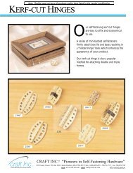
WOODEN HINGES<br />
A wooden hinge can be used to make hinged table leafs or hinged legs for a collapsible table. The hinge pins are<br />
normally are made of stainless steel, but you can use other materials, including wood for that purpose.<br />
180° HINGES WITH A DRILLED HOLE<br />
The workpiece for this simple hinge must be narrow enough to make the hole for the hinge pin with a drill bit.<br />
This hinge has at least a range of motion of 180° (Figs. 45A and 45B).<br />
Fig. 45A<br />
Fig. 45B<br />
Step 1 -<br />
Step 2 -<br />
Step 3 -<br />
Step 4 -<br />
Step 5 -<br />
Step 6 -<br />
Step 7-<br />
Round over the ends of the two workpieces (Fig. 45C).<br />
Use a drill press to drill a hole in the center of each board for the hinge pin (Fig. 45D).<br />
Make an end-to-end box cut. (Make the depth-of-cut slightly deeper than the thickness of the boards<br />
(Fig. 45E).<br />
Make the length of the hinge pin narrower than the width of the boards<br />
Hold the boards together, align the holes, and insert the pin (Fig. 45F).<br />
Glue wooden plugs in the workpiece to hold the pins in place.(Fig. 45G).<br />
Cut off the protruding part of the plugs and sand (Fig. 45H).<br />
Fig. 45C Fig. 45D Fig. 45E<br />
Fig. 45F Fig. 45G Fig. 45H<br />
26
270° HINGES WITH A DRILLED HOLE<br />
Follow the previous directions for 180° Hinge and use the following photos to help you make a hinge that will have<br />
270° or more range of motion. Cut the boards as shown in Fig. 46A.<br />
Fig. 46A Fig. 46B Fig. 46C<br />
180° HINGES WITH ROUTER-MADE GROOVES<br />
When the width of the workpieces are too wide for a drill bit to<br />
make the hole, use this method.Two boards <strong>com</strong>pose each<br />
hinge half. Make a half-round dado at the end of the<br />
workpieces. When you glue the boards together, these two<br />
dados make the hole for the hinge pin.<br />
Fig. 47A<br />
Step 1 -<br />
Step 2 -<br />
Step 3 -<br />
Step 4 -<br />
Step 5 -<br />
Step 6 -<br />
Step 7-<br />
Use a router to make a half-round dado near the end of each of the four boards. Make the diameter of the<br />
groove equal to the diameter of the hinge pin, and the depth of cut half the diameter of the hinge pin (Fig.<br />
48A).<br />
Insert the metal rod (long enough to stick out of both ends of the board) in one of the dados.<br />
Glue a second workpiece to the first (Fig. 48B).<br />
Repeat Steps two and three for the other half of the hinge.<br />
After the glue dries, remove the metal rod.<br />
Round over the ends of the glued boards.<br />
Make the rest of the hinge the same as you would with the 180° Hinge With a Drilled Hole.<br />
Fig. 48A<br />
Fig. 48B<br />
27
270° HINGES WITH ROUTER-MADE GROOVES<br />
This method uses two pieces of wood glued together for each<br />
hinge-half. One of the pieces is very short.<br />
Fig. 49A<br />
Step 1 -<br />
Step 2 -<br />
Step 3 -<br />
Step 4 -<br />
Step 5 -<br />
Step 6 -<br />
Use a router to make a half-round dado near the end of a board. Make the diameter of the groove equal<br />
to the diameter of the hinge pin, and the depth of cut half the diameter of the hinge pin(Fig. 49B).<br />
Round over the ends of the boards (Fig. 49C).<br />
Cut off the ends of the boards. The length of the cut-off should be twice the thickness of the board (Fig.<br />
49D).<br />
Repeat Step 1 for the remaining longer boards.<br />
For both hinge halves, glue the short board to the long board with the metal hinge rod in the grooves and<br />
sticking out both sides of the wood (Fig. 49E)<br />
After the glue dries, remove the metal rod.<br />
Make the rest of the hinge the same as you would with the 180° Hinge With a Drilled Hole.<br />
Fig. 49B<br />
Fig. 49C<br />
Fig. 49D<br />
Fig. 49E<br />
28
ANGLED JOINTS<br />
You can join boards at angles other than 90°. Four different methods are shown below by using the through <strong>dovetail</strong><br />
procedure.<br />
OBTUSE ANGLED JOINTS<br />
The simplest of these angled joints is the obtuse-angled<br />
<strong>dovetail</strong>. In this joint, two boards are joined together at an<br />
angle greater than 90°.<br />
This joint can be made with either the template mounted to the<br />
base of the <strong>jig</strong> or to a clamping board. If the angle is 100° or<br />
greater, you must use the clamping board method.<br />
Joint<br />
Angle<br />
Fig. 50A<br />
SETUP WITH THE TEMPLATE MOUNTED TO THE BASE OF THE JIG<br />
Step 1 -<br />
Step 2 -<br />
Step 3 -<br />
Step 4 -<br />
Step 5 -<br />
Make an angled insert according to one of the drawings (Figs. 51A and 51B).Match the angle of the insert<br />
with the joint angle. If the workpiece is wider than 6" use the 12" insert.<br />
Make sure that the 1/4-20 flat-head screw does not protrude (A) Fig. 51C.<br />
Remove the small front knobs, the front clamping rod, and the front clamping U channel. Leave the<br />
springs.<br />
Use two 1/2" 1/4-20 flat-head screws to secure the angled insert to the front of the base of the <strong>jig</strong>, with<br />
the thicker edge of the insert up. If you are using the 6" insert, install it in the 2 holes on the right (Fig.<br />
51C).<br />
Replace the hardware that was removed in STEP 3.<br />
MAKE TWO COUNTERSINKS FOR<br />
1/4-20 FLATHEAD SCREWS.<br />
THE 1/4-20 SCREWS MUST NOT<br />
PROTRUDE PAST THE OUTER<br />
SURFACE OF THE INSERT.<br />
DRILL TWO<br />
1/4 " HOLES<br />
MAKE TWO COUNTERSINKS FOR<br />
1/4-20 FLATHEAD SCREWS.<br />
THE 1/4-20 SCREWS MUST NOT<br />
PROTRUDE PAST THE OUTER<br />
SURFACE OF THE INSERT.<br />
DRILL TWO<br />
1/4<br />
" HOLES<br />
INSERT ANGLE<br />
INSERT ANGLE<br />
1-1/8 "<br />
9/16 "<br />
1-1/8<br />
"<br />
9/16 "<br />
12 "<br />
1 "<br />
4 "<br />
1 "<br />
14 "<br />
1/4<br />
"<br />
7 "<br />
1/4 "<br />
Fig. 51A<br />
Fig. 51B<br />
Fig. 51C<br />
A<br />
29
SETUP WITH THE TEMPLATE MOUNTED TO A CLAMPING BOARD<br />
Step 1 -<br />
Step 2 -<br />
Step 3 -<br />
Make an angled clamping board according to the drawing (Fig. 52B). Match the angle of the<br />
clamping board to the joint angle.<br />
If necessary, create flat places on the clamping board parallel with the opposite side so that the<br />
clamps can grab.<br />
Attach the template to the clamping board with #10 wood screws. Position the angled surface on<br />
the side of the template with the straight fingers (Fig. 52A).<br />
Fig. 52A<br />
DRILL PILOT HOLES<br />
FOR #10 WOOD SCREWS<br />
1 "<br />
Fig. 52B<br />
19 "<br />
13 "<br />
3 "<br />
2 "<br />
WOOD GRAIN<br />
ANGLE OF<br />
BOARDS<br />
3 "<br />
CUTTING THE TAILS<br />
Step 1 -<br />
Step 2 -<br />
Step 3 -<br />
Step 4 -<br />
Step 5 -<br />
Step 6 -<br />
Step 7-<br />
Cut the end of the tail board according to the <strong>instruction</strong>s in the drawing (Fig. 53A). You can make these<br />
cuts on a table saw with the blade beveled (Fig. 53B). Set the miter gauge at 90° for the first cut, then use<br />
a tenoning <strong>jig</strong> for the second cut (Fig. 53C).<br />
If you use the template mounted to the base of the <strong>jig</strong>, mount the board with the outside face toward the<br />
base of the <strong>jig</strong>. Center the edges of the board between two fingers (Fig. 53D).<br />
If you use the board-mounted template, clamp the board with the outside face toward the angled surface<br />
of the clamping board. Center the board between two fingers.<br />
Align the template using the “tails” line.<br />
If the angle is steep, the “tails” line may not align with the wood. The joint will be fine if you place the straight<br />
portion of the template fingers directly over the tail board (A) Fig. 53E. Otherwise, you may have to use an<br />
angled clamping board.<br />
Set the router bit depth where the sides of the board are at a slight angle (Fig. 53F).<br />
Cut the tails and remove the tail board.<br />
THICKNESS OF PIN BOARD<br />
FIRST CUT<br />
90°<br />
SECOND CUT<br />
Fig. 53B<br />
ANGLE BETWEEN BOARDS<br />
OUTSIDE<br />
SURFACE<br />
OF BOARD<br />
INSIDE<br />
SURFACE<br />
OF BOARD<br />
Fig. 53A<br />
Fig. 53C<br />
30
Fig. 53D Fig. 53E Fig. 53F<br />
CUTTING THE PINS<br />
Step 1 -<br />
Step 2 -<br />
Step 3 -<br />
Step 4 -<br />
Step 5 -<br />
Step 6 -<br />
Step 7-<br />
Step 8-<br />
Step 9-<br />
Cut the end of the pin board according to the drawing (54A).<br />
If you use the template mounted to the base of the <strong>jig</strong> and a 12" angled insert, remove the small front<br />
knobs, clamping rod and clamping U channel. Then remove the angled insert and reinstall the hardware.<br />
Hold the boards together and mark the end of the pin board along the edges of the tails (Fig. 54B).<br />
Rotate the template so that the angled fingers are facing toward you.<br />
If you use the template mounted to the base of the <strong>jig</strong>, mount the pin board with the outside surface facing<br />
away from the base of the <strong>jig</strong>. Center the marks on the end of the board between the angled fingers of<br />
the template (Fig. 54C).<br />
If you use the template mounted on a clamping board, clamp the pin board with the outside surface facing<br />
away from the straight surface of the clamping board. Center the marks on the end of the board between<br />
the angled fingers of the template.<br />
Use the "PINS” line to align the template with the edge of the pin board.<br />
Set the router bit depth slightly more than the thickness of the tail board. Make sure that the bit does not<br />
contact the base of the <strong>jig</strong>.<br />
Cut the pins and remove the pin board.<br />
MAKE ANGLED CUT<br />
ANGLE BETWEEN BOARDS<br />
Fig. 54B<br />
INSIDE<br />
SURFACE<br />
OF BOARD<br />
OUTSIDE<br />
SURFACE<br />
OF BOARD<br />
Fig. 54A<br />
Fig. 54C<br />
FITTING THE JOINT<br />
Fitting the joint is the same as fitting the standard <strong>dovetail</strong>. With the angled template fingers facing you, move the<br />
template toward you for a tighter joint or away for a looser joint.<br />
31
ACUTE ANGLED JOINTS<br />
Fig. 55A<br />
An acute angle joint joins two boards together at an angle less<br />
than 90°. The acute angled joint is very similar in construction to<br />
the the obtuse angled joint and can be used with the obtuse<br />
angled joint to make boxes with angles other than 90°.<br />
SETUP<br />
Joint<br />
Angle<br />
Use the same setup as you would for the obtuse angled joint. Use 180° minus the joint angle for the insert angle<br />
when you make your angled insert or your angled clamping board.<br />
NOTE: If the acute angle and the obtuse angle add up to 180°, use the same setup for both joints.<br />
CUTTING THE TAILS<br />
Step 1 -<br />
Step 2 -<br />
Step 3 -<br />
Step 4 -<br />
Step 5 -<br />
Cut the end of the tail board according to the <strong>instruction</strong>s on the drawing (Fig. 56A). Steep angles or thin<br />
wood will make for a weak joint. Make this cut on a table saw with the blade beveled. Set the miter gauge<br />
at 90° for the first cut and use a tenoning <strong>jig</strong> for the second cut (Fig. 56B).<br />
Clamp the workpiece as you did for the obtuse-angled joint, except face the outside surface of the board<br />
away from the base of the <strong>jig</strong>.<br />
Step 3 is identical to Step 5 in "CUTTING THE TAILS" of the obtuse-angled section.<br />
Set the router bit depth to where the step is in the tail board.<br />
Cut the tails and remove the tail board.<br />
FIRST CUT<br />
SECOND CUT<br />
THICKNESS OF PIN BOARD<br />
THIRD CUT<br />
(IF NECESSARY)<br />
ANGLE BETWEEN BOARDS<br />
OUTSIDE<br />
SURFACE<br />
OF BOARD<br />
INSIDE<br />
SURFACE<br />
OF BOARD<br />
Fig. 56A<br />
Fig. 56B<br />
CUTTING THE PINS<br />
Step 1 -<br />
Step 2 -<br />
Step 3 -<br />
Step 4 -<br />
Cut the end of the pin board according to the <strong>instruction</strong>s on the drawing (Fig. 57A). Steep angles or thin<br />
wood will make for a weak joint. Make this cut on a table saw with the blade beveled, and with the miter<br />
gauge set at 90°.<br />
Clamp the workpiece as you did for the obtuse-angled joint.<br />
Hold the boards together and mark the end of the pin board at the edges of the tails.<br />
The remainder of the steps, including fitting the joint, are identical to the obtuse-angled joint section.<br />
32
MAKE ANGLED CUT<br />
ANGLE BETWEEN BOARDS<br />
INSIDE<br />
SURFACE<br />
OF BOARD<br />
OUTSIDE<br />
SURFACE<br />
OF BOARD<br />
Fig. 57A<br />
SLANTED-SIDE JOINTS<br />
Two boards joined at 90°, with one board slanted to the side is known as a slanted-side joint. This method is used<br />
to make a box with the ends at right angles to the table, but with the sides tilted outward (cradles, planters, magazine<br />
racks).<br />
Fig. 58A<br />
Fig. 58B<br />
NOTE: Usually, the tails are cut into the ends and the pins are cut into the sides.<br />
CUTTING THE TAILS<br />
Step 1 -<br />
Step 2 -<br />
Step 3 -<br />
Cut the ends of the tail board at the desired angle. Note that when the angle is approaching 15° that the<br />
tails weaken (Fig. 59A).<br />
Mount the board so that the outside surface faces the base of the <strong>jig</strong> and the edge is against the template<br />
(Fig. 59B).<br />
Cut the tails in the same manner as you would the standard <strong>dovetail</strong>s.<br />
Fig. 59A<br />
Fig. 59B<br />
33
CUTTING THE PINS<br />
Step 1 -<br />
Step 2 -<br />
Step 3 -<br />
Step 4 -<br />
Step 5 -<br />
Cut the pin board according to Fig. 60A.<br />
Hold the boards together and mark the pin board at the edges of the tails (Fig. 60B).<br />
Rotate the template so that the tapered fingers for cutting the pins is facing you.<br />
Mount the pin board with the outside surface facing away from the base of the <strong>jig</strong>. Center the<br />
marks from STEP 2 between the tapered fingers (A) Fig. 60C.<br />
Cut the pins in the same manner as you would with standard <strong>dovetail</strong>s.<br />
EXTRA WIDTH FOR BEVEL<br />
TAIL BOARD<br />
PIN BOARD<br />
Fig. 60B<br />
EDGE OF TAIL BOARD<br />
PIN BOARD WIDTH IS EQUAL TO<br />
EDGE OF TAIL BOARD PLUS<br />
EXTRA WIDTH FOR BEVEL<br />
Fig. 60A<br />
FITTING THE JOINT<br />
A<br />
Fig. 60C<br />
Fitting the joint is the same as fitting the standard<br />
<strong>dovetail</strong>. HINT: Use pieces of scrap wood the same<br />
thickness and species of wood to make test pin boards<br />
until the template is adjusted for a perfect fit.<br />
Fig. 61A<br />
COMPOUND-ANGLE JOINTS<br />
Two boards joined at 90°, with both boards slanted to the side is known as a <strong>com</strong>pound-angle joint. This method is<br />
used to make serving trays or planters.<br />
Fig. 62C<br />
Side<br />
Angle<br />
Side<br />
Angle<br />
Fig. 62A<br />
Fig. 62B<br />
34
NOTE: The <strong>instruction</strong>s given here are for templates mounted to the base of the <strong>jig</strong>. However, this joint can also be<br />
made with templates mounted to angled clamping boards. You must use the angled clamping board for steeper<br />
angles.<br />
Use the following table for setting up your table saw for these cuts:<br />
DESIRED SIDE ANGLE<br />
85°<br />
80°<br />
75°<br />
70°<br />
65°<br />
MITER gauge ANGLE<br />
85.0°<br />
80.1°<br />
75.5°<br />
71.1°<br />
67.1°<br />
BLADE TILT ANGLE<br />
89.6°<br />
88.3°<br />
86.2°<br />
83.3°<br />
79.7°<br />
SETUP<br />
Use the same setup as you would for the obtuse angled joint. Use the blade tilt angle for making the angle insert or<br />
the angled clamping block. Bevel the edges according to the drawing (Fig. 63A).<br />
BEVEL THE EDGES OF THE TAIL AND PIN BOARDS<br />
FIRST CUT<br />
BLADE TILT ANGLE<br />
THICKNESS OF PIN BOARD<br />
90.0°<br />
SECOND CUT<br />
OUTSIDE<br />
SURFACE<br />
OF BOARD<br />
INSIDE<br />
SURFACE<br />
OF BOARD<br />
Fig. 63A<br />
Fig. 64A<br />
Step 1 -<br />
Cut the end of the tail board according to the drawing (Fig. 64A). Set the miter gauge and tilt the blade to<br />
the values in the above table. Make the first cut with the board flat on the table surface and guide it with<br />
the miter gauge (Fig. 64B). Make the second cut with a tenoning <strong>jig</strong> (Fig. 64C).<br />
Fig. 64B<br />
Fig. 64C<br />
35
CUTTING THE TAILS<br />
Step 2 -<br />
Step 3 -<br />
Step 4 -<br />
Step 5 -<br />
With the angled insert attached to the base of the <strong>jig</strong>, mount the tail board with the outside surface of the<br />
board facing the <strong>jig</strong> and with the board centered between the fingers of the template (Fig. 64D).<br />
Align the template using the “Tails” alignment line. If the angle is so steep that the “Tails” alignment line<br />
will not work, you may have to use an angled clamping board. However, as long as the rounded part of<br />
the fingers go past the edge of the wood, the set up will work fine as is.<br />
Set the router bit depth to where the sides of the board go off at a slight angle (Fig. 64E).<br />
Cut the tails and remove the tail board.<br />
Fig. 64D<br />
Fig. 64E<br />
CUTTING THE PINS<br />
Step 1 -<br />
Step 2 -<br />
Step 3 -<br />
Step 4 -<br />
Step 5 -<br />
Step 6 -<br />
Step 7 -<br />
Step 8 -<br />
Cut the end of the tail board according to the drawing (Fig. 65A). Set the miter gauge and tilt the blade to<br />
the values in the previous table. Remember that the miter gauge for the tailboard must be tilted opposite<br />
for the pin board.<br />
If you are using the 12" long angled insert, remove it from the <strong>jig</strong>.<br />
Hold the outside surfaces of the boards together and mark the pin board at the edges of the tail (Fig. 65B).<br />
Rotate the template so that the angled fingers for cutting the pins is facing you.<br />
Mount the pin board with the outside surface facing away from the base of the <strong>jig</strong>. Center the marks on<br />
the end of the board between the angled fingers of the template (A) Fig. 65C.<br />
Use the "PINS" alignment line to align the template with the edge of the pin board.<br />
Set the router bit depth to slightly more than the thickness of the tail board, but prevent the bit from<br />
contacting the base of the <strong>jig</strong>..<br />
Cut the pins and remove the pin board.<br />
BLADE TILT ANGLE<br />
MAKE ANGLED CUT<br />
Fig. 65B<br />
INSIDE<br />
SURFACE<br />
OF BOARD<br />
OUTSIDE<br />
SURFACE<br />
OF BOARD<br />
Fig. 65A<br />
A<br />
Fig. 65C<br />
36
FITTING THE JOINT<br />
Fitting the joint is the same as fitting the standard <strong>dovetail</strong>. HINT: Use pieces of scrap wood the same thickness and<br />
species of wood to make test pin boards until the template is adjusted for a perfect fit.<br />
INLAYED JOINTS<br />
The 4200 series <strong>dovetail</strong> <strong>jig</strong>s will allow you to make joints with inlays of different colored wood for a very unique look.<br />
INLAYED THROUGH DOVETAIL<br />
The inlayed through <strong>dovetail</strong> is produced by utilizing 2<br />
through <strong>dovetail</strong>s, one on top of the other.<br />
SETUP<br />
Fig. 67A<br />
Select two sets of router bit <strong>com</strong>binations from the table for “Through Dovetail Router Bit Combinations" in the<br />
section "TABLES OF COMMONLY AVAILABLE ROUTER BIT SIZES". Use the following table to determine the<br />
thickness of the inlay line<br />
Router Bit Set Combinations<br />
T1 & T2<br />
T1 & T3<br />
T1 & T4<br />
T2 & T3<br />
T2 & T4<br />
T3 & T4<br />
Thickness of Inlay Line in<br />
Decimal Measurements<br />
0.056<br />
0.083<br />
0.097<br />
0.028<br />
0.042<br />
0.014<br />
Approximate Thickness<br />
in Fractional Measurements<br />
7/128<br />
11/128<br />
3/32<br />
1/32<br />
5/128<br />
1/64<br />
Use the set with the bigger <strong>dovetail</strong> bit for the first joint. Make sure that the length of the cutter on the bit is at least<br />
the thickness of the pin board plus the thickness of the inlay line. At the same time, make sure that the length of the<br />
cutter on the straight bit is at least the thickness of the tail board.<br />
Use the set with the smaller <strong>dovetail</strong> bit for the second joint. Make sure that the length of the cutter is at least the<br />
thickness of the pin board. At the same time, make sure that the length of the cutter on the straight bit is at least<br />
the thickness of the tail board plus the thickness of the inlay line.<br />
Plane the inlay board the same thickness as the thickness of the pin board plus the thickness of the inlay line from<br />
the table above.<br />
MAKE THE FIRST JOINT<br />
Make the first joint the same way that you would make a standard through <strong>dovetail</strong> (Fig. 68A).<br />
If the <strong>jig</strong> is set up to make through <strong>dovetail</strong>s with the tails and pins slightly protruding or recessed, use the alternate<br />
method of setting the router bit depth found in the section on “MISCELLANEOUS TECHNIQUES”.<br />
Glue the joint together and let it dry.<br />
37
CUT OFF THE INLAY BOARD<br />
After the joint has dried, cut the inlay board to an amount equal to the thickness of the inlay (Fig. 68B).<br />
Fig. 68A<br />
Fig. 68B<br />
If desired, you can cut off the small area shown from the remainder of the inlay wood (Fig. 68C). If left on, the<br />
<strong>com</strong>pleted joint will have an extra amount of material on the inside. another alternative is to bevel this extra material<br />
(Fig. 68D).<br />
Fig. 68C<br />
Fig. 68D<br />
MAKE THE SECOND JOINT<br />
Make the second joint the same way as you would a standard through <strong>dovetail</strong>. HINT: Do not move the offset guides<br />
after making the first joint.<br />
Fig. 69A<br />
Fig. 69B<br />
INLAYED HALF-BLIND DOVETAIL<br />
Make this joint by producing two half-blind <strong>dovetail</strong>s on<br />
top of each other.<br />
Fig. 70B<br />
38
SETUP<br />
Select one set of <strong>dovetail</strong> bits from the table for Combinations for Half-blind <strong>dovetail</strong>s with the pins and the tails cut<br />
separately in the section"TABLES OF COMMONLY AVAILABLE ROUTER BIT SIZES". Use the following table to<br />
determine the thickness of the inlay line:<br />
Dovetail Bit Set<br />
H1<br />
H2<br />
H3<br />
H4<br />
H5<br />
Thickness of Inlay Line in<br />
Decimal Measurements<br />
0.100<br />
0.050<br />
0.042<br />
0.028<br />
0.014<br />
Approximate Thickness<br />
in Fractional Measurements<br />
13/128<br />
3/64<br />
5/128<br />
1/32<br />
1/64<br />
NOTE: If the thickness of the inlay line is very thin, you may have difficulty cutting the inlay correctly.<br />
MAKE THE FIRST JOINT<br />
The first joint is identical to that described in the section on Half-Blind Dovetail Bits with the Pins and Tails Cut<br />
Separately under the chapter “ALTERNATE ROUTER BITS”. Use the inlay material as the pin board (normally the<br />
drawer front). For the first joint, cut the tail board with the larger <strong>dovetail</strong> bit and the pin board with the smaller<br />
<strong>dovetail</strong> bit.<br />
Glue the joint and let it dry.<br />
CUT OFF THE INLAY BOARD<br />
After the joint has dried, cut off the inlay board. Cut off the pin board flush<br />
with the inside edge of the tail board (Fig. 71B). Then cut off the front edge of<br />
the inlay board (Fig. 71C), making sure that the remainder of the inlay (A) Fig<br />
71D is cut so that the thickness is equal to the thickness found in the table<br />
on the previous page.<br />
Fig. 71A<br />
A<br />
Fig. 71B Fig. 71C Fig. 71D<br />
39
MAKE THE SECOND JOINT<br />
The second joint is also identical to that described in the section on Half-Blind Dovetail Bits with the Pins and Tails<br />
Cut Separately under the chapter “ALTERNATE ROUTER BITS”. Use the board from the previous section as the tail<br />
board. Cut the tail board with the smaller <strong>dovetail</strong> bit and the pin board with the larger <strong>dovetail</strong> bit.<br />
HINT: Using two routers to make these joints will make your work easier.<br />
Fig. 72A<br />
Fig. 72B<br />
INLAYED BOX JOINT<br />
This joint is made by cutting two box joints on top of each other.<br />
SETUP<br />
Select one set of <strong>dovetail</strong> bits from the table for “Box Joint Bit Combinations" in the section"TABLES OF<br />
COMMONLY AVAILABLE ROUTER BIT SIZES". Use the following table to determine the thickness of the inlay line:<br />
Straight Bit Set<br />
B2<br />
B3<br />
Thickness of Inlay Line<br />
1/16"<br />
1/8"<br />
NOTE: If the thickness of the inlay line is very thin, you may have difficulty in cutting the inlay correctly.<br />
You must plane the inlay board to the thickness of the second board plus the thickness of the inlay line.<br />
MAKE THE FIRST JOINT<br />
The first joint is identical to a box joint with alternate router bit sizes as found in the section “ALTERNATE ROUTER<br />
BITS”. Make a box joint with the first board and the inlay board. Use the larger straight bit with the first board and<br />
the smaller bit with the inlay board.<br />
If the <strong>jig</strong> is set up to make through <strong>dovetail</strong>s with the tails and pins slightly protruding or recessed, use the alternate<br />
method of setting the router bit depth found in the section on “MISCELLANEOUS TECHNIQUES”.<br />
NOTE: For the tails and pins to be flush, be careful to make the bit depth very precise.<br />
CUT OFF THE INLAY BOARD<br />
After the joint has dried, cut off most of the inlay board. Leave an amount equal to the thickness of the inlay.<br />
MAKE THE SECOND JOINT<br />
The second joint is also identical to a box joint with alternate router bit sizes as found in the section “ALTERNATE<br />
ROUTER BITS”. Make a box joint with the board from the previous section and the second board. Use the smaller<br />
straight bit with the board from the previous section and the larger bit with the second board.<br />
HINT: this section of your project (aligning the joint) is easier if you do not move the offset guides after making the<br />
first joint.<br />
40
TABLES OF COMMONLY AVAILABLE ROUTER BIT SIZES<br />
THROUGH DOVETAIL ROUTER BIT COMBINATIONS<br />
Combination Number<br />
7° Dovetail Bit<br />
Straight Bit<br />
T1<br />
T2<br />
T3<br />
T4<br />
3/4"<br />
5/8"<br />
9/16"<br />
17/32"<br />
3/16"<br />
5/16"<br />
3/8"<br />
13/32"<br />
HALF-BLIND DOVETAIL BITS<br />
Bit (Diameter and Angle)<br />
Approximate* Depth of Cut<br />
17/32"<br />
17/32"<br />
9/16"<br />
5/8"<br />
7°<br />
14°<br />
7°<br />
14°<br />
13/32"<br />
3/16"<br />
3/4"<br />
9/16"<br />
COMBINATIONS FOR HALF-BLIND DOVETAILS<br />
WITH THE PINS AND THE TAILS CUT SEPARATELY.<br />
Combination<br />
Number<br />
Large Dovetail Bit<br />
(Diameter and Angle)<br />
Small Dovetail Bit<br />
(Diameter and Angle)<br />
Approximate*<br />
Depth of Cut<br />
H1<br />
3/4"<br />
14°<br />
1/2"<br />
14°<br />
9/16"<br />
H2<br />
5/8"<br />
14°<br />
1/2"<br />
14°<br />
3/8"<br />
H3<br />
5/8"<br />
7°<br />
17/32"<br />
7°<br />
7/8"<br />
H4<br />
5/8"<br />
7°<br />
9/16"<br />
7°<br />
1"<br />
H5<br />
9/16"<br />
7°<br />
17/32"<br />
7°<br />
5/8"<br />
*<br />
The actual depth-of-cut may be a little deeper or shallower than what appears on this table. Since vendors use<br />
different manufacturing tolerances on bit dimensions, use the manufacturer’s advertised bit dimensions only as<br />
a guide. Remember that a small amount of variation within tolerances can have a large impact on the final depthof-cut.<br />
Combination Number<br />
B1<br />
B2<br />
B3<br />
BOX JOINT BIT COMBINATIONS<br />
Larger Straight Bit<br />
1/2"<br />
9/16"<br />
5/8"<br />
Smaller Straight Bit<br />
1/2"<br />
7/16"<br />
3/8"<br />
41
TROUBLESHOOTING<br />
For assistance with your tool, visit our website at www.porter-cable.<strong>com</strong> for a list of service centers or call the Porter-Cable<br />
help line at 1-800-487-8665.<br />
MAINTENANCE<br />
KEEP TOOL CLEAN<br />
Periodically blow out all air passages with dry <strong>com</strong>pressed air. Clean all plastic parts with a soft damp cloth. NEVER<br />
use solvents to clean plastic parts. They could possibly dissolve or otherwise damage the material.<br />
WEAR ANSI Z87.1 SAFETY GLASSES WHILE USING COMPRESSED AIR.<br />
SERVICE AND REPAIRS<br />
All quality tools will eventually require servicing or replacement of parts due to wear from normal use. These<br />
operations, including brush inspection and replacement, should ONLY be performed by either an AUTHORIZED<br />
PORTER-CABLE SERVICE STATION or a PORTER-CABLE·DELTA FACTORY SERVICE CENTER. All repairs made by<br />
these agencies are fully guaranteed against defective material and workmanship. We cannot guarantee repairs made<br />
or attempted by anyone other than these agencies.<br />
Should you have any questions about your tool, feel free to write us at any time. In any <strong>com</strong>munications, please give<br />
all information shown on the nameplate of your tool (model number, type, serial number, etc.).<br />
SERVICE<br />
REPLACEMENT PARTS<br />
When servicing use only identical replacement parts.<br />
SERVICE AND REPAIRS<br />
All quality tools will eventually require servicing or replacement of parts due to wear from normal use. These<br />
operations, including brush inspection and replacement, should ONLY be performed by either an AUTHORIZED<br />
PORTER-CABLE SERVICE STATION or a PORTER-CABLE·DELTA FACTORY SERVICE CENTER. All repairs made by<br />
these agencies are fully guaranteed against defective material and workmanship. We cannot guarantee repairs made<br />
or attempted by anyone other than these agencies.<br />
Should you have any questions about your tool, feel free to write us at any time. In any <strong>com</strong>munications, please give<br />
all information shown on the nameplate of your tool (model number, type, serial number, etc.).<br />
ACCESSORIES<br />
A <strong>com</strong>plete line of accessories is available from your Porter-Cable·Delta Supplier, Porter-Cable·Delta Factory<br />
Service Centers, and Porter-Cable Authorized Service Stations. Please visit our Web Site www.porter-cable.<strong>com</strong><br />
for a catalog or for the name of your nearest supplier.<br />
Since accessories other than those offered by Porter-Cable·Delta have not been tested with this<br />
product, use of such accessories could be hazardous. For safest operation, only Porter-Cable·Delta<br />
re<strong>com</strong>mended accessories should be used with this product.<br />
42
WARRANTY<br />
PORTER-CABLE LIMITED<br />
ONE YEAR WARRANTY<br />
Porter-Cable warrants its Professional Power Tools for a period of one year from the date of original purchase. We will repair or replace at our option, any part or<br />
parts of the product and accessories covered under this warranty which, after examination, proves to be defective in workmanship or material during the warranty<br />
period. For repair or replacement return the <strong>com</strong>plete tool or accessory, transportation prepaid, to your nearest Porter-Cable Service Center or Authorized Service<br />
Station. Proof of purchase may be required. This warranty does not apply to repair or replacement required due to misuse, abuse, normal wear and tear or repairs<br />
attempted or made by other than our Service Centers or Authorized Service Stations.<br />
ANY IMPLIED WARRANTY, INCLUDING THE IMPLIED WARRANTIES OF MERCHANTABILITY AND FITNESS FOR A PARTICULAR PURPOSE, WILL LAST ONLY<br />
FOR ONE (1) YEAR FROM THE DATE OF PURCHASE.<br />
To obtain information on warranty performance please write to: PORTER-CABLE CORPORATION, 4825 Highway 45 North, Jackson, Tennessee 38305; Attention:<br />
Product Service. THE FOREGOING OBLIGATION IS PORTER-CABLE’S SOLE LIABILITY UNDER THIS OR ANY IMPLIED WARRANTY AND UNDER NO<br />
CIRCUMSTANCES SHALL PORTER-CABLE BE LIABLE FOR ANY INCIDENTAL OR CONSEQUENTIAL DAMAGES. Some states do not allow limitations on how<br />
long an implied warranty lasts or the exclusion or limitation of incidental or consequential damages, so the above limitation or exclusion may not apply to you.<br />
This warranty gives you specific legal rights and you may also have other legal rights which vary from state to state.<br />
43
ARIZONA<br />
Tempe 85282 (Phoenix)<br />
2400 West Southern Avenue<br />
Suite 105<br />
Phone: (602) 437-1200<br />
Fax: (602) 437-2200<br />
CALIFORNIA<br />
Ontario 91761 (Los Angeles)<br />
3949A East Guasti Road<br />
Phone: (909) 390-5555<br />
Fax: (909) 390-5554<br />
San Diego 92111<br />
7638 Clairemnot Blvd.<br />
Phone: (858) 277-9595<br />
Fax: (858) 277-9696<br />
San Leandro 94577 (Oakland)<br />
3039 Teagarden Street<br />
Phone: (510) 357-9762<br />
Fax: (510) 357-7939<br />
COLORADO<br />
Arvada 80003 (Denver)<br />
8175 Sheridan Blvd., Unit S<br />
Phone: (303) 487-1809<br />
Fax: (303) 487-1868<br />
FLORIDA<br />
Davie 33314 (Miami)<br />
4343 South State Rd. 7 (441)<br />
Unit #107<br />
Phone: (954) 321-6635<br />
Fax: (954) 321-6638<br />
PORTER-CABLE • DELTA SERVICE CENTERS<br />
(CENTROS DE SERVICIO DE PORTER-CABLE • DELTA)<br />
Parts and Repair Service for Porter-Cable • Delta Machinery are Available at These Locations<br />
(Obtenga Refaccion de Partes o Servicio para su Herramienta en los Siguientes Centros de Porter-Cable • Delta)<br />
Tampa 33609<br />
4538 W. Kennedy Boulevard<br />
Phone: (813) 877-9585<br />
Fax: (813) 289-7948<br />
GEORGIA<br />
Forest Park 30297 (Atlanta)<br />
5442 Frontage Road,<br />
Suite 112<br />
Phone: (404) 608-0006<br />
Fax: (404) 608-1123<br />
ILLINOIS<br />
Addison 60101 (Chicago)<br />
400 South Rohlwing Rd.<br />
Phone: (630) 424-8805<br />
Fax: (630) 424-8895<br />
Woodridge 60517 (Chicago)<br />
2033 West 75th Street<br />
Phone: (630) 910-9200<br />
Fax: (630) 910-0360<br />
MARYLAND<br />
Elkridge 21075 (Baltimore)<br />
7397-102 Washington Blvd.<br />
Phone: (410) 799-9394<br />
Fax: (410) 799-9398<br />
MASSACHUSETTS<br />
Franklin 02038 (Boston)<br />
Franklin Industrial Park<br />
101E Constitution Blvd.<br />
Phone: (508) 520-8802<br />
Fax: (508) 528-8089<br />
MICHIGAN<br />
Madison Heights 48071 (Detroit)<br />
30475 Stephenson Highway<br />
Phone: (248) 597-5000<br />
Fax: (248) 597-5004<br />
MINNESOTA<br />
Minneapolis 55429<br />
5522 Lakeland Avenue North<br />
Phone: (763) 561-9080<br />
Fax: (763) 561-0653<br />
MISSOURI<br />
North Kansas City 64116<br />
1141 Swift Avenue<br />
Phone: (816) 221-2070<br />
Fax: (816) 221-2897<br />
St. Louis 63119<br />
7574 Watson Road<br />
Phone: (314) 968-8950<br />
Fax: (314) 968-2790<br />
NEW YORK<br />
Flushing 11365-1595 (N.Y.C.)<br />
175-25 Horace Harding Expwy.<br />
Phone: (718) 225-2040<br />
Fax: (718) 423-9619<br />
NORTH CAROLINA<br />
Charlotte 28270<br />
9129 Monroe Road, Suite 115<br />
Phone: (704) 841-1176<br />
Fax: (704) 708-4625<br />
OHIO<br />
Columbus 43214<br />
4560 Indianola Avenue<br />
Phone: (614) 263-0929<br />
Fax: (614) 263-1238<br />
Cleveland 44125<br />
8001 Sweet Valley Drive<br />
Unit #19<br />
Phone: (216) 447-9030<br />
Fax: (216) 447-3097<br />
OREGON<br />
Portland 97230<br />
4916 NE 122 nd Ave.<br />
Phone: (503) 252-0107<br />
Fax: (503) 252-2123<br />
PENNSYLVANIA<br />
Willow Grove 19090<br />
(Philadelphia)<br />
520 North York Road<br />
Phone: (215) 658-1430<br />
Fax: (215) 658-1433<br />
TEXAS<br />
Carrollton 75006 (Dallas)<br />
1300 Interstate 35 N, Suite 112<br />
Phone: (972) 446-2996<br />
Fax: (972) 446-8157<br />
Houston 77043<br />
4321 Sam Houston Parkway,<br />
West<br />
Suite 180<br />
Phone: (713) 983-9910<br />
Fax: (713) 983-6645<br />
WASHINGTON<br />
Auburn 98001(Seattle)<br />
3320 West Valley HWY, North<br />
Building D, Suite 111<br />
Phone: (253) 333-8353<br />
Fax: (253) 333-9613<br />
Authorized Service Stations are located in many large cities. Telephone 800-438-2486 or 731-541-6042 for assistance locating one.<br />
Parts and accessories for Porter-Cable·Delta products should be obtained by contacting any Porter-Cable·Delta Distributor, Authorized<br />
Service Center, or Porter-Cable·Delta Factory Service Center. If you do not have access to any of these, call 800-223-7278 and you will<br />
be directed to the nearest Porter-Cable·Delta Factory Service Center. Las Estaciones de Servicio Autorizadas están ubicadas en muchas<br />
grandes ciudades. Llame al 800-438-2486 ó al 731-541-6042 para obtener asistencia a fin de localizar una. Las piezas y los accesorios<br />
para los productos Porter-Cable·Delta deben obtenerse poniéndose en contacto con cualquier distribuidor Porter-Cable·Delta, Centro<br />
de Servicio Autorizado o Centro de Servicio de Fábrica Porter-Cable·Delta. Si no tiene acceso a ninguna de estas opciones, llame al<br />
800-223-7278 y le dirigirán al Centro de Servicio de Fábrica Porter-Cable·Delta más cercano.<br />
CANADIAN PORTER-CABLE • DELTA SERVICE CENTERS<br />
ALBERTA<br />
Bay 6, 2520-23rd St. N.E.<br />
Calgary, Alberta<br />
T2E 8L2<br />
Phone: (403) 735-6166<br />
Fax: (403) 735-6144<br />
BRITISH COLUMBIA<br />
8520 Baxter Place<br />
Burnaby, B.C.<br />
V5A 4T8<br />
Phone: (604) 420-0102<br />
MANITOBA<br />
1699 Dublin Avenue<br />
Winnipeg, Manitoba<br />
R3H 0H2<br />
Phone: (204) 633-9259<br />
Fax: (204) 632-1976<br />
ONTARIO<br />
505 Southgate Drive<br />
Guelph, Ontario<br />
N1H 6M7<br />
Phone: (519) 767-4132<br />
Fax: (519) 767-4131<br />
QUÉBEC<br />
1515 ave.<br />
St-Jean Baptiste, Suite 160<br />
Québec, Québec<br />
G2E 5E2<br />
Phone: (418) 877-7112<br />
Fax: (418) 877-7123<br />
1447, Begin<br />
St-Laurent, (Montréal),<br />
Québec<br />
H4R 1V8<br />
Phone: (514) 336-8772<br />
Fax: (604) 420-3522<br />
Fax: (514) 336-3505<br />
The following are trademarks of PORTER-CABLE • DELTA (Las siguientes son marcas registradas de PORTER-CABLE • DELTA S.A.) (Les marques<br />
suivantes sont des marques de fabriquant de la PORTER-CABLE • DELTA): Auto-Set ® , BAMMER ® , B.O.S.S. ® , Builder’s Saw ® , Contractor’s Saw ® ,<br />
Contractor’s Saw II, Delta ® , DELTACRAFT ® , DELTAGRAM, Delta Series 2000, DURATRONIC, Emc², FLEX ® , Flying Chips, FRAME SAW ® ,<br />
Grip Vac, Homecraft ® , INNOVATION THAT WORKS ® , Jet-Lock ® , JETSTREAM ® , ‘kickstand ® , LASERLOC ® , MICRO-SET ® , Micro-Set ® , MIDI LATHE ® ,<br />
MORTEN, NETWORK, OMNIJIG ® , POCKET CUTTER ® , PORTA-BAND ® , PORTA-PLANE ® , PORTER-CABLE ® &(design), PORTER-<br />
CABLE ® PROFESSIONAL POWER TOOLS, PORTER-CABLE REDEFINING PERFORMANCE, Posi-Matic ® , Q-3 ® &(design), QUICKSAND ® &(design),<br />
QUICKSET, QUICKSET II ® , QUICKSET PLUS, RIPTIDE&(design), SAFE GUARD II ® , SAFE-LOC ® , Sanding Center ® , SANDTRAP ® &(design), SAW<br />
BOSS ® , Sawbuck, Sidekick ® , SPEED-BLOC ® , SPEEDMATIC ® , SPEEDTRONIC ® , STAIR EASE ® , The American Woodshop ® &(design), The Lumber<br />
Company ® &(design), THE PROFESSIONAL EDGE ® , THE PROFESSIONAL SELECT ® , THIN-LINE, TIGER ® , TIGER CUB ® , TIGER SAW ® ,<br />
TORQBUSTER ® , TORQ-BUSTER ® , TRU-MATCH, TWIN-LITE ® , UNIGUARD ® , Unifence ® , UNIFEEDER, Unihead ® , Uniplane, Unirip ® , Unisaw ® ,<br />
Univise ® , Versa-Feeder ® , VERSA-PLANE ® , WHISPER SERIES ® , WOODWORKER’S CHOICE.<br />
Trademarks noted with and ® are registered in the United States Patent and Trademark Office and may also be registered in other countries. Las<br />
Marcas Registradas con el signo de y ® son registradas por la Oficina de Registros y Patentes de los Estados Unidos y también pueden estar<br />
registradas en otros países.<br />
PC7.2-0105-149