Manual (PDF) - Rose Electronics
Manual (PDF) - Rose Electronics
Manual (PDF) - Rose Electronics

Create successful ePaper yourself
Turn your PDF publications into a flip-book with our unique Google optimized e-Paper software.
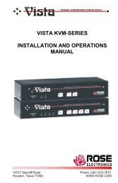
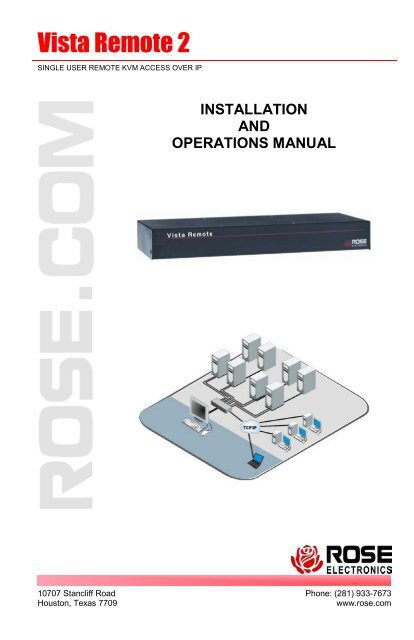
Vista Remote 2<br />
SINGLE USER REMOTE KVM ACCESS OVER IP<br />
INSTALLATION<br />
AND<br />
OPERATIONS MANUAL<br />
10707 Stancliff Road<br />
Houston, Texas 7709<br />
Phone: (281) 933-7673<br />
www.rose.com
LIMITED WARRANTY<br />
<strong>Rose</strong> <strong>Electronics</strong> ® warrants Vista Remote 2 to be in good working order for one year from the<br />
date of purchase from <strong>Rose</strong> <strong>Electronics</strong> or an authorized dealer. Should this product fail to be<br />
in good working order at any time during this one-year warranty period, <strong>Rose</strong> <strong>Electronics</strong> will, at<br />
its option, repair or replace the Unit as set forth below. Repair parts and replacement units will<br />
be either reconditioned or new. All replaced parts become the property of <strong>Rose</strong> <strong>Electronics</strong>.<br />
This limited warranty does not include service to repair damage to the Unit resulting from<br />
accident, disaster, abuse, or unauthorized modification of the Unit, including static discharge<br />
and power surges.<br />
Limited Warranty service may be obtained by delivering this unit during the one-year warranty<br />
period to <strong>Rose</strong> <strong>Electronics</strong> or an authorized repair center providing a proof of purchase date. If<br />
this Unit is delivered by mail, you agree to insure the Unit or assume the risk of loss or damage<br />
in transit, to prepay shipping charges to the warranty service location, and to use the original<br />
shipping container or its equivalent. You must call for a return authorization number first. Under<br />
no circumstances will a unit be accepted without a return authorization number. Contact an<br />
authorized repair center or <strong>Rose</strong> <strong>Electronics</strong> for further information.<br />
ALL EXPRESS AND IMPLIED WARRANTIES FOR THIS PRODUCT INCLUDING THE<br />
WARRANTIES OF MERCHANTABILITY AND FITNESS FOR A PARTICULAR PURPOSE,<br />
ARE LIMITED IN DURATION TO A PERIOD OF ONE YEAR FROM THE DATE OF<br />
PURCHASE, AND NO WARRANTIES, WHETHER EXPRESS OR IMPLIED, WILL APPLY<br />
AFTER THIS PERIOD. SOME STATES DO NOT ALLOW LIMITATIONS ON HOW LONG AN<br />
IMPLIED WARRANTY LASTS, SO THE ABOVE LIMITATION MAY NOT APPLY TO YOU.<br />
IF THIS PRODUCT IS NOT IN GOOD WORKING ORDER AS WARRANTIED ABOVE, YOUR<br />
SOLE REMEDY SHALL BE REPLACEMENT OR REPAIR AS PROVIDED ABOVE. IN NO<br />
EVENT WILL ROSE ELECTRONICS BE LIABLE TO YOU FOR ANY DAMAGES INCLUDING<br />
ANY LOST PROFITS, LOST SAVINGS OR OTHER INCIDENTAL OR CONSEQUENTIAL<br />
DAMAGES ARISING OUT OF THE USE OF OR THE INABILITY TO USE SUCH PRODUCT,<br />
EVEN IF ROSE ELECTRONICS OR AN AUTHORIZED DEALER HAS BEEN ADVISED OF<br />
THE POSSIBILITY OF SUCH DAMAGES, OR FOR ANY CLAIM BY ANY OTHER PARTY.<br />
SOME STATES DO NOT ALLOW THE EXCLUSION OR LIMITATION OF INCIDENTAL OR<br />
CONSEQUENTIAL DAMAGES FOR CONSUMER PRODUCTS, SO THE ABOVE MAY NOT<br />
APPLY TO YOU. THIS WARRANTY GIVES YOU SPECIFIC LEGAL RIGHTS AND YOU MAY<br />
ALSO HAVE OTHER RIGHTS WHICH MAY VARY FROM STATE TO STATE.<br />
NOTE: This equipment has been tested and found to comply with the limits for a Class B digital<br />
device, pursuant to Part 15 of the FCC Rules. These limits are designed to provide reasonable<br />
protection against harmful interference when the equipment is operated in a commercial<br />
environment. This equipment generates, uses, and can radiate radio frequency energy and, if<br />
not installed and used in accordance with the instruction manual, may cause harmful<br />
interference to radio communications. Operation of this equipment in a residential area is likely<br />
to cause harmful interference in which case the user will be required to correct the interference<br />
at his own expense.<br />
IBM, AT, and PS/2 are trademarks of International Business Machines Corp.<br />
Microsoft and Microsoft Windows are registered trademarks of Microsoft Corp.<br />
Any other trademarks mentioned in this manual are acknowledged to be the<br />
property of the trademark owner.<br />
Copyright <strong>Rose</strong> <strong>Electronics</strong> 2008. All rights reserved.<br />
No part of this manual may be reproduced, stored in a retrieval system, or transcribed in any form or any<br />
means, electronic or mechanical, including photocopying and recording, without the prior written permission<br />
of <strong>Rose</strong> <strong>Electronics</strong>.<br />
<strong>Rose</strong> <strong>Electronics</strong> Part # MAN-VR2<br />
Printed In the United States of America - Revision 1.3
FCC / IC STATEMENTS, EU DECLARATION OF CONFORMITY<br />
FEDERAL COMMUNICATIONS COMMISSION AND INDUSTRY CANADA<br />
RADIO-FREQUENCY INTERFERENCE STATEMENTS<br />
This equipment generates, uses and can radiate radio frequency energy and if not installed and<br />
used properly, that is in strict accordance with the manufacturer’s instructions may cause<br />
interference to radio communication. It has been tested and found to comply with the limits for<br />
a Class B digital device in accordance with the specifications of Part 15 of FCC rules, which are<br />
designed to provide reasonable protection against such interference when the equipment is<br />
operated in a commercial environment. Operation of this equipment in a residential area is<br />
likely to cause interference, in which case the user at his own expense will be required to take<br />
whatever measures may be necessary to correct the interference.<br />
Changes or modifications not expressly approved by the party responsible for compliance could<br />
void the user’s authority to operate the equipment.<br />
This digital apparatus does not exceed the Class A limits for radio noise emission from digital<br />
apparatus set out in the Radio Interference Regulation of Industry Canada.<br />
Le présent appareil numérique n’émet pas de bruits radioélectriques dépassant les limites<br />
applicables aux appareils numériques de la classe A prescrites dans le Règlement sur le<br />
brouillage radioélectrique publié par Industrie Canada.<br />
EUROPEAN UNION DECLARATION OF CONFORMITY<br />
This equipment complies with the requirements of the European EMC directive 89/336/EEC in<br />
respect of EN55022 (Class B), EN50082-1 and EN60555-2 standards and the Low Voltage<br />
Directive.
TABLE of CONTENTS<br />
Contents Page #<br />
System Introduction ................................................................................................................... 1<br />
Features ................................................................................................................................ 2<br />
Package contents .................................................................................................................. 2<br />
<strong>Rose</strong> <strong>Electronics</strong> web site ...................................................................................................... 3<br />
Product Registration .................................................................................................................. 3<br />
System Overview ...................................................................................................................... 4<br />
Vista Remote 2 Models ............................................................................................................. 5<br />
Vista Remote 2 Installation ........................................................................................................ 6<br />
Connecting the KVM station ................................................................................................... 6<br />
Connecting the Computers .................................................................................................... 7<br />
Connecting to the network ..................................................................................................... 7<br />
Configuring the Vista Remote 2 IP Input module .................................................................... 8<br />
Connecting Remotely .............................................................................................................. 13<br />
Remote Configuration .............................................................................................................. 14<br />
User Accounts ......................................................................................................................... 15<br />
Unit Configuration .................................................................................................................... 16<br />
Unit Advanced Configuration ................................................................................................... 17<br />
Time and Date Configuration ................................................................................................... 19<br />
Network Configuration ............................................................................................................. 20<br />
Host Configuration ................................................................................................................... 21<br />
Logging and Status ................................................................................................................. 22<br />
KVM Switch Module Configuration .......................................................................................... 24<br />
Change the computer names ............................................................................................... 25<br />
Configure appearance ......................................................................................................... 26<br />
Configure security ................................................................................................................ 28<br />
Configure mouse type .......................................................................................................... 29<br />
Configure keyboard type ...................................................................................................... 30<br />
Configure miscellaneous ...................................................................................................... 31<br />
Save .................................................................................................................................... 32<br />
Exit ...................................................................................................................................... 32<br />
Remote System Operation ...................................................................................................... 33<br />
Connecting using a web browser ......................................................................................... 33<br />
VNC Viewer Toolbar ................................................................................................................ 34<br />
Controls Tab ............................................................................................................................ 35<br />
Host Tab.................................................................................................................................. 37<br />
Keyboard Commands .............................................................................................................. 39<br />
Keyboard command description ........................................................................................... 40<br />
Troubleshooting ....................................................................................................................... 42<br />
Maintenance and Repair.......................................................................................................... 45<br />
Technical Support ................................................................................................................... 45
Figures Page #<br />
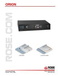
Figure 1. Vista Remote 2 Models .............................................................................................. 5<br />
Figure 2. Connecting a KVM ..................................................................................................... 6<br />
Figure 3. Connecting Computers .............................................................................................. 7<br />
Figure 4. Connecting to the Network ......................................................................................... 7<br />
Figure 5. Configuration OSD ..................................................................................................... 8<br />
Figure 6. Unit Configuration OSD .............................................................................................. 8<br />
Figure 7. Network Configuration.............................................................................................. 10<br />
Figure 8. Secure Key calculation............................................................................................. 11<br />
Figure 9. Standard Logon screen ............................................................................................ 11<br />
Figure 10. Control menu ......................................................................................................... 12<br />
Figure 11. Remote Configuration Menu .................................................................................. 14<br />
Figure 12. User Accounts ....................................................................................................... 15<br />
Figure 13. Unit Advanced Configuration .................................................................................. 17<br />
Figure 14. Time and Date Configuration ................................................................................. 19<br />
Figure 15. Configure Network ................................................................................................. 20<br />
Figure 16. Configure Host ....................................................................................................... 21<br />
Figure 17. KVM Switch Module OSD ...................................................................................... 24<br />
Figure 18. Change computer names ....................................................................................... 25<br />
Figure 19. Change appearance .............................................................................................. 26<br />
Figure 20. Switch module security settings ............................................................................. 28<br />
Figure 21. Configure mouse type ............................................................................................ 29<br />
Figure 22. Configure Keyboard ............................................................................................... 30<br />
Figure 23. Configure Misc ....................................................................................................... 31<br />
Figure 24. Save Switch settings .............................................................................................. 32<br />
Figure 25. VNC Viewer Toolbar .............................................................................................. 34<br />
Tables Page #<br />
Table 1. Keyboard Commands ............................................................................................... 40<br />
Appendices Page #<br />
Appendix A – General specifications ....................................................................................... 48<br />
Appendix B – Part Numbers .................................................................................................... 48<br />
Appendix C – RackMount ....................................................................................................... 49<br />
Appendix D – IP Access Control ............................................................................................. 50<br />
Appendix E – VNC Viewer connection options ........................................................................ 52<br />
Appendix E – VNC viewer window options .............................................................................. 58<br />
Appendix F – Browser viewer options ..................................................................................... 59<br />
Appendix G – Supported video modes .................................................................................... 61<br />
Appendix H – Typematic Rate ................................................................................................ 62
INTRODUCTION<br />
System Introduction<br />
Thank you for choosing Vista Remote 2 from <strong>Rose</strong> <strong>Electronics</strong> for your network access<br />
solutions. This intelligent and innovative product is the result of <strong>Rose</strong> <strong>Electronics</strong> commitment<br />
to providing state of the art, economical switching solutions for today’s demanding workplace.<br />
Vista Remote 2, when installed and connected to your network, allows you full access and<br />
control of the connected computers from the built in viewer client or any web browser from<br />
almost anywhere. This flexible and powerful product uses the Real VNC client software that is<br />
designed for very secure, encrypted, and password protected exchange of information between<br />
the computers and the remote viewer. The Vista Remote 2 sets a new standard for an easy<br />
and very secure way to remotely manage The Vista Remote 2 is available in a 4 port or 8 port<br />
model.<br />
The Vista Remote 2 is different in the way it manages remote access to your systems. All of<br />
the computers that will be remotely connected remain completely unchanged and can run their<br />
usual operating system normally. They only need to be connected to the Vista Remote 2 unit.<br />
Being totally operating system independent, a user can remotely connect to different computers<br />
with no problem.<br />
Whatever your remote accessing needs are, the versatility of the Vista Remote 2 from <strong>Rose</strong><br />
<strong>Electronics</strong> can fulfill those needs. It can be installed at any network level and connected to<br />
computers running most operating system.<br />
Installing the Vista Remote 2<br />
consists of:<br />
1. Configuring the unit to be<br />
compatible and accessible<br />
with your network<br />
2. Connecting the unit to a<br />
local KVM station<br />
3. Connecting your computers<br />
to access and<br />
4. Connecting to the network<br />
Once installed and configured<br />
you have full control of the<br />
selected computer provided<br />
your security profile permits it.<br />
The Vista Remote 2 consists of an IP input module and a KVM switch module. Each module<br />
serves a unique purpose in access control and KVM switching control. The IP input module<br />
controls the accessibility, security, and state-of-the-art encryption to the unit. It can be<br />
accessed locally, remotely over your network, or from any workstation connected to the<br />
internet. All access methods require a user ID and password to gain access to the units IP<br />
input module. Access to the units IP input module from any remote user is via any supported<br />
web browser. The Vista Remote 2 is further enhanced by the use of Real VNC that allows for<br />
the creation of ciphered user communications. Additionally, an optional user ID and password<br />
and other set-up parameters can be set-up to gain access and use the KVM switch module.<br />
This additional user ID can be set-up for each user needing access to the KVM switch module.<br />
Vista Remote 2 Installation and Operations <strong>Manual</strong> 1
Features<br />
• Models available:<br />
4-port model<br />
8-port model<br />
• Solid-state embedded unit, has no disk drive for maximum reliability<br />
• Remote application (Real VNC or Java applet) can be installed directly from the unit<br />
• Local KVM port for configuring and direct access to the connected computers<br />
• Connect to the unit directly, from a network workstation, or over IP using any supported<br />
web browser.<br />
• Access remote computers by simple keyboard commands or an on-screen list of<br />
computers<br />
• Supports video resolution up to 1600 x 1200 @ 75hz<br />
• Password security prevents unauthorized configuration and Unit access<br />
• Remote access requires a user ID and password.<br />
• IP lockout feature for incorrect login (IP address shown as “Blacklisted” in log file)<br />
• All transmissions to and from a remote user are encrypted with the latest AES 128 bit<br />
encryption technology.<br />
• Up to 16 remote user accounts can be set-up each with separate access permission<br />
levels.<br />
• Scan function sequences through the connected computers at rates of 1 to 999 seconds<br />
• Four different screen savers are available<br />
• Rack mount kits available for 19”, 23”, or 24” racks<br />
Package contents<br />
The package contents consist of the following:<br />
• The Vista Remote 2 unit<br />
• RJ12 Serial Cable<br />
• +5VDC Power Adapter / Power cord<br />
• Installation and operations manual CD<br />
• Quick Start Guide<br />
Cables are usually ordered separately. If the package contents are not correct, contact <strong>Rose</strong><br />
<strong>Electronics</strong> or your reseller so the problem can be quickly resolved.<br />
2 Vista Remote 2 Installation and Operations <strong>Manual</strong>
<strong>Rose</strong> <strong>Electronics</strong> web site<br />
Visit our web site at www.rose.com for additional information on Vista Remote 2 and other<br />
products offered by <strong>Rose</strong> <strong>Electronics</strong> that are designed for data center applications, classroom<br />
environments, and many other access and switching applications.<br />
Product Registration<br />
Take advantage of the following when you register your <strong>Rose</strong> <strong>Electronics</strong> products online at<br />
http://www.rose.com/htm/online-registrationform.htm:<br />
• <strong>Rose</strong> Standard Warranty Plus...<br />
• Free Lifetime Firmware Updates<br />
• Free Lifetime Technical Support<br />
• 30 Day Money Back Guarantee<br />
• Priority “First-in-Line” Status for Tech Support<br />
Vista Remote 2 Installation and Operations <strong>Manual</strong> 3
OVERVIEW<br />
System Overview<br />
Vista Remote 2 is a versatile and powerful product that can extend the range of access to your<br />
computers from anywhere in the world. It is designed to provide seamless and trouble-free<br />
access from any workstation on your network or any remote user to any connected computer.<br />
You can connect to and control any of the connected computers by simple keyboard<br />
commands or an on-screen list of computers. Each computer can be assigned a unique name<br />
that makes sense for your system. Names like sales, production, and administration make it<br />
easy to recognize and connect to.<br />
Access control for the users can be set-up to provide access restrictions to the configuration<br />
menus and the unit. The installation and configuration section explains all the features and<br />
functions of the Vista Remote 2 and how to customize it to fit your business needs.<br />
The Vista Remote 2 is designed with the highest regard for security. Remote access requires a<br />
user ID and password. All transmissions, to and from a remote workstation and Vista Remote 2<br />
uses the versatile and very secure RealVNC viewer and are encrypted with the latest<br />
encryption technology. Login, time-out, User ID and password add to the security of the system.<br />
The UltraView Remote 2 consists of an IP input module and a KVM switch module. Each<br />
module serves a unique purpose in access control and KVM switching control. The IP input<br />
module controls the accessibility, security, and state-of-the-art encryption to the unit. The KVM<br />
switching module controls and manages the CPU port switching.<br />
Vista Remote 2<br />
Remote Users<br />
Local User<br />
Vista Remote 2 unit<br />
Network<br />
Computers Local KVM Station Remote<br />
(4 or 8) workstation<br />
Typical connection diagram<br />
4 Vista Remote 2 Installation and Operations <strong>Manual</strong>
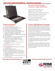
Vista Remote 2 Models<br />
(Part Number KVL-1R4UA/OV/2)<br />
Connector Type<br />
Power Adapter<br />
CPU (4) DB25F<br />
KVM (1) DB25F<br />
RS232 RJ11F<br />
LINK RJ45F<br />
(Part Number KVL-1R8UA/OV/2)<br />
Connector Type<br />
Power Adapter<br />
CPU (8) DB25F<br />
KVM (1) DB25F<br />
RS232 RJ11F<br />
LINK RJ45F<br />
Figure 1. Vista Remote 2 Models<br />
Vista Remote 2 Installation and Operations <strong>Manual</strong> 5
INSTALLATION<br />
Vista Remote 2 Installation<br />
Installing the Vista Remote 2 is a very easy process and should be performed by a designated<br />
administrator. The administrator will install, configure, and set-up user access profiles. A<br />
network administrator will need to assign an IP address to the unit (if needed) and set-up<br />
firewall and network access to the unit.<br />
The following installation procedure is a guide to properly install and configure the Vista<br />
Remote 2. The following items are needed to install the Vista Remote 2:<br />
1. A valid IP address to assign to the unit (if not using DHCP feature)<br />
2. VGA monitor<br />
3. PS/2 keyboard<br />
4. PS/2 mouse<br />
5. RJ45 network cable<br />
6. KVM Adapter cable (DB25M to PS/2F-PS/2F-HD15F)<br />
7. CPU Adapter cable(s) (DB25M to PS/2M-PS/2M-HD15M)<br />
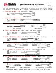
Connecting the KVM station<br />
Connect the KVM stations PS/2 keyboard, video monitor and PS/2 mouse cables to the<br />
corresponding connectors on the KVM adapter cable as shown in Figure 2. The KVM station’s<br />
video monitor should be equal or better than any of the connected computers. Connect the<br />
DB25M end of the KVM cable to the KVM DB25F port on the rear panel of the Vista Remote 2<br />
unit.<br />
KVM Adapter Cable<br />
KVM Station<br />
Figure 2. Connecting a KVM<br />
6 Vista Remote 2 Installation and Operations <strong>Manual</strong>
Connecting the Computers<br />
Connect each computer to the Vista Remote 2 using the appropriate CPU adapter cable<br />
designed to interface to the type of computer being connected (PS/2, Unix, SUN, DEC, Apple,<br />
etc). Connect the DB25M end of the CPU adapter cable to the desired DB25F CPU port on the<br />
rear panel of the unit. Connect the other end of the cable to the corresponding ports on the<br />
computer (keyboard, monitor, and mouse). Refer to Figure 3.<br />
Remote computer<br />
connections<br />
CPU adapter<br />
cable(s)<br />
Figure 3. Connecting Computers<br />
Connecting to the network<br />
Connect a network cable from the RJ45 connector on the rear panel of the Vista Remote 2 and<br />
to your network (See Figure 4)<br />
Network connection<br />
Figure 4. Connecting to the Network<br />
Vista Remote 2 Installation and Operations <strong>Manual</strong> 7
UNIT CONFIGURATION<br />
Configuring the Vista Remote 2 IP Input module<br />
When you locally connect to Vista Remote 2 unit for the first time the Unit and Network must<br />
be configured. Follow the recommended procedure below to configure all models:<br />
Make all cable connections to the KVM station, network, and computers<br />
Apply power to all devices (Computers, Vista Remote 2, and Monitor).<br />
Make sure a computer is connected to CPU port #1 and that computer is powered on.<br />
If no computer is connected to port #1, the OSD menu screens may not sync.<br />
With power applied, a standard login screen will display on the KVM monitor<br />
Login on to the unit using the default user ID, admin and no password<br />
After a successful login, the remote computer’s video will display on the KVM monitor.<br />
Press the CTRL + ALT + C keys simultaneously to display the configuration menu options<br />
as shown below: (Unit connection screen may display after initial connection is made)<br />
Figure 5. Configuration OSD<br />
Select “Unit Configuration” and the below screen will display<br />
Figure 6. Unit Configuration OSD<br />
8 Vista Remote 2 Installation and Operations <strong>Manual</strong>
Hardware<br />
The hardware version level is displayed in this field.<br />
Firmware<br />
The Vista Remote 2 firmware version is displayed in this field<br />
Keyboard Layout<br />
Using the left and right arrow keys, select the keyboard type expected from the host computers.<br />
Admin password<br />
Enter an administrator password of at least six characters that has a mix of letters and<br />
numerals. The background color provides an indication of password suitability. It is initially red<br />
to indicate that the password is not sufficient. When a password with reasonable strength has<br />
been entered it changes to blue.<br />
Unit Name<br />
You can assign a unit name to the Vista Remote 2.<br />
Hot Keys<br />
Use the left and right arrow keys to select a different hot key combination. This hot key<br />
combination is used to invoke the OSD menu and other keyboard commands<br />
Screen saver<br />
Use the left and right arrow keys to set the time for the screen saver to activate.<br />
Time and Date<br />
Set the time and date to the correct values. Use the 24 hour base inputs. All entries in the<br />
activity log are time stamped using this information.<br />
Encryption<br />
Arrange this setting according to your security requirements.<br />
When all items have been updated, click on “Next” to configure the network information. The<br />
network information entered (IP Address, Net Mask, and Gateway) must be compatible with the<br />
network Vista Remote 2 will be connected to.<br />
Vista Remote 2 Installation and Operations <strong>Manual</strong> 9
NETWORK CONFIGURATION<br />
Configuring the Network<br />
Figure 7. Network Configuration<br />
MAC address<br />
Media Access Control Address – this is the unique and unchangeable code that was hard<br />
coded within your Vista Remote 2 unit when it was built. It consists of two 6-digit hexadecimal<br />
(base 16) numbers separated by colons. A section of the MAC address identifies the<br />
manufacturer, while the remainder is effectively the unique electronic serial number of your<br />
particular unit<br />
Use DHCP/IP address/Net Mask/Gateway/VNC port/HTTP Port<br />
1. You need to either set the DHCP option to ‘Yes’ or manually enter a valid IP address,<br />
Net mask and Gateway. If you set the option to use DHCP, remote users must be<br />
informed of the IP address assigned so they can remotely access the unit.<br />
2. Change the IP Address to the IP address assigned to the unit by your network<br />
administrator that is compatible with your network.<br />
3. Change the Net Mask and Gateway addresses if needed.<br />
4. The VNC and HTTP ports should remain set to 5900 and 80, respectively, unless they<br />
clash with an existing setup within the network.<br />
5. When all network information has been entered, click on “Next” to calculate a “Secure<br />
Key”.<br />
10 Vista Remote 2 Installation and Operations <strong>Manual</strong>
Screen #3 is a secure keys screen that will display after the network information has been<br />
entered.<br />
Figure 8. Secure Key calculation<br />
This screen uses mouse movements and keyboard inputs to create random data. This<br />
unpredictable information is then combined with several other factors to develop the basis of<br />
the encryption keys that are used to establish secure remote links.<br />
With every mouse move and key press the single dash will move across the progression bar<br />
(unless the same key is pressed repeatedly). Periodically, a new star character will be added to<br />
the bar as the random data are accepted as part of the new encryption key. When the bar is<br />
full, the final encryption keys for your Vista Remote 2 will be created – this process takes<br />
roughly 30 to 40 seconds.<br />
Once the secure key has been calculated, the Vista Remote 2 will restart and present a<br />
standard logon screen as shown below. Logon to the unit with the correct Username and<br />
password.<br />
Figure 9. Standard Logon screen<br />
Vista Remote 2 Installation and Operations <strong>Manual</strong> 11
To view the menu options press . (If the default hotkeys were<br />
altered on the Configure Unit screen, use the new hotkeys plus C)<br />
Figure 10. Control menu<br />
Logoff<br />
Select this option to close your current session and display the screensaver.<br />
Restore mouse functions<br />
Select this tab to revive a mouse that has ceased to function correctly. The Vista Remote 2<br />
provides a feature to reinstate PS/2 mouse communications. (Does not apply if using a USB<br />
mouse.)<br />
There are two main types of data formats used by current PC mice; ‘PS/2’ format and the more<br />
recent IntelliMouse ® ’ format introduced by Microsoft. These use slightly different data<br />
arrangements and it is important to know which type was being used before you hot-plugged<br />
the computer to the Vista Remote 2. The previous setting depends both on the type of mouse<br />
and the type of driver, as various combinations of PS/2 and IntelliMouse are possible. Using the<br />
incorrect restore function may produce unpredictable results and require the computer to be rebooted.<br />
Using a keyboard and monitor<br />
directly connected to the Vista<br />
Remote 2, log on and then press the<br />
hotkey sequence to<br />
view the options menu.<br />
1. Select the ‘Restore mouse<br />
functions’ option to display:<br />
2. Select one of the following<br />
options:<br />
3. Restore Standard Mouse – if<br />
PS/2 mode is required, or<br />
Restore IntelliMouse – if<br />
IntelliMouse mode is required.<br />
4. Select “Back” to return to the<br />
Control menu.<br />
12 Vista Remote 2 Installation and Operations <strong>Manual</strong>
Configuration<br />
Select the “Configuration” tab to gain access to the Unit and Network configuration menus.<br />
You can also reset the Vista Remote 2 to its initial state.<br />
Access mode<br />
Allows you to choose between the Shared mode (where all other logged on users can see your<br />
operations) and the Private mode (where the screens of all other users are blanked).<br />
Host<br />
Indicates the currently selected host computer and allows you to select others. This item will be<br />
blank unless host details have been set-up.<br />
Return to host<br />
Quits the menu and returns to the host screen.<br />
Connecting Remotely<br />
With the Unit and the Network configured properly, start a web browser like IE or Netscape<br />
from any workstation connected to the same network your Vista Remote 2 is connected to.<br />
Type in the Vista Remote 2’s assigned IP address (Example (http://168.192.0.41) in the URL<br />
field. The Vista Remote 2 will respond with the below screen. There may be initial login and<br />
connect screens displayed.<br />
(NOTE: See Appendix E for additional VNC Viewer options)<br />
Click on the “Connect using built-in Java VNC viewer” option and the Vista Remote 2 will install<br />
a temporary Java applet on the requesting computer and then display the connected<br />
computer’s video in the browser’s VNC viewer window. In the upper right corner of the window<br />
is a “Configure” tab. Click on this tab to display the remote configuration option menu as shown<br />
below.<br />
Vista Remote 2 Installation and Operations <strong>Manual</strong> 13
Remote Configuration<br />
Connect remotely to the Vista Remote 2 unit from any network workstation. When connected,<br />
click on the “Configure” tab in the upper right corner of the display. The below configuration<br />
menu will display. Some of the remote configuration menus are similar to the local configuration<br />
menus.<br />
Clicking on the Configure tab<br />
Displays the configuration window<br />
Figure 11. Remote Configuration Menu<br />
(Following describes each of the Configuration Tabs.<br />
Allows you to create and manage up to sixteen separate user<br />
accounts, each with separate access permissions. Account #1 is<br />
User Accounts<br />
the admin account. Enter User name, password. Tick/un-tick the<br />
Local and Remote options that are appropriate to the user.<br />
Unit Configuration<br />
Time & Date<br />
Network Configuration<br />
Host Configuration<br />
Logging and Status<br />
LDAP Configuration<br />
Return to Host<br />
Allows you to modify unit settings within the Vista Remote 2. You<br />
can define the keyboard, set-up the admin account, assign a name<br />
to the unit, screensaver time and encryption options<br />
Set the time and date, this time stamps the log files<br />
Configures the network IP, network mask, gateway, VNC port, HTTP<br />
port. You can alter any of the existing network settings plus you can<br />
set-up the IP access control feature that lets you specifically include<br />
or exclude certain addresses or networks<br />
Allows configuration of various details for each host system<br />
connected to Vista Remote 2. 128 entries max, Add host names,<br />
Users and Hotkey.<br />
Provides various details about the Vista Remote 2 activity<br />
Configures unit for LDAP<br />
Exit the configuration menu system and return to the host computer<br />
14 Vista Remote 2 Installation and Operations <strong>Manual</strong>
User Accounts<br />
Selecting user accounts will display the following menu.<br />
Figure 12. User Accounts<br />
The first of the sixteen accounts is the admin account and is the only account with access rights<br />
to the configuration menus. The user name and access rights are fixed for the admin account.<br />
The only change possible for this account is the password.<br />
There are fifteen user account positions.<br />
To create a new account<br />
1 Enter the required User Name to activate that position (the Password, access tick<br />
boxes, and Auto Logon positions will become editable).<br />
2 Optionally enter a password for the user account.<br />
3 Tick/un-tick the Local, Remote, and the Auto Logon options that are appropriate to<br />
the user.<br />
(A tick indicates the user has permission for that function)<br />
4 Click the Save button to register your changes.<br />
User Name - 1-16 characters max, lower case characters or numbers only. No symbols or<br />
upper case characters are permissible.<br />
Password - 1-16 characters max, case sensitive and can include certain keyboard symbols.<br />
The password background remains amber while the Vista Remote 2 considers your entered<br />
password to be too easy to guess. A suitable password is best constructed using a mixture of<br />
more than 6 letters, numbers and punctuation characters.<br />
Local - When ticked, the selected user can gain access using the local KVM station directly<br />
connected to the Vista Remote 2.<br />
Remote - When ticked, the selected user can gain access via an IP network link, such as a<br />
local intranet or the wider Internet (depending on how the Vista Remote 2 is connected and the<br />
network access is configured.).<br />
Auto Logon - When ticked, and the unit is powered on, logs in a single user that is set for auto<br />
logon only if the user is allowed local access.<br />
Vista Remote 2 Installation and Operations <strong>Manual</strong> 15
Unit Configuration<br />
The ‘Unit Configuration “option tab will display the following menu.<br />
Hardware Version<br />
Indicates the version of the electronic circuitry within the Vista Remote 2 unit.<br />
Firmware Version<br />
Indicates the version of the hardwired software within the Vista Remote 2 flash memory. This<br />
may be updated using the flash upgrade procedure.<br />
Host Keyboard Layout<br />
Use the arrow buttons to match the keyboard layout expected by the host system.<br />
Admin Password<br />
Enter the password that will be used to gain administrator access to the Vista Remote 2. There<br />
can only be one admin user and only that user is given access to the configuration menus.<br />
Unit Name<br />
The name entered here will be displayed on the local menus and the remote VNC<br />
viewer/browser windows.<br />
Local Hot Key Sequence<br />
Use the arrow buttons to select an appropriate hot key sequence for the locally connected<br />
keyboard. This sequence is used in combination with other key presses to access the onscreen<br />
menus and to change between hosts. The options are: Ctrl+Alt (default), Ctrl+Shift,<br />
Alt+Shift, Alt Gr, Left + Right Alt, Left Ctrl + Alt or Right Ctrl + Alt.<br />
Screensaver Timeout<br />
Use the arrow keys to select an appropriate period of inactivity before a screensaver is<br />
displayed and the user is logged out. This setting applies to local users only and once the<br />
screensaver is displayed, for security purposes the user is required to log in again. The timeout<br />
period can be selected between 5 minutes and 1 day (24 hours), it cannot be disabled.<br />
16 Vista Remote 2 Installation and Operations <strong>Manual</strong>
Encryption<br />
Three encryption options are available; Always on, Prefer off, Prefer on. The one to choose<br />
depends on the specific details of your installation. The use of encryption imposes a slight<br />
performance overhead of roughly 10% but is highly secure against third party intrusion.<br />
Encryption settings<br />
The Unit configuration page offers three encryption settings:<br />
• Always on - This setting will force all viewers to use encryption. Note: This setting will<br />
preclude any VNC viewer versions that do not support encryption.<br />
• Prefer off - This setting does not enforce encryption unless a viewer specifically<br />
requests it. If a viewer has its ‘Let server choose’ setting, then an un-encrypted link will<br />
be set up.<br />
• Prefer on - This setting generally enforces encryption unless an earlier viewer version<br />
is unable to support it, in which case the link will be un-encrypted. If a viewer has its<br />
‘Let server choose’ setting, then the link will be encrypted.<br />
Unit Advanced Configuration<br />
The “Advanced Configuration” tab will display advanced options that generally do not need<br />
modifying.<br />
Figure 13. Unit Advanced Configuration<br />
Force VNC protocol 3.3<br />
IMPORTANT: The use of this option is not recommended. VNC protocol 3.3 is a legacy version<br />
that does not offer any encryption.<br />
Idle timeout<br />
Determines the period of inactivity on a remote connection before the user is logged out. The<br />
idle timeout period can be set to any time span, expressed in minutes. Note: The Screensaver<br />
option serves a similar purpose for local connections. A value of 0 will disable the timeout.<br />
Protocol timeout<br />
Sets the time period by which responses should have been received to outgoing data packets.<br />
If the stated period is exceeded, then a connection is considered lost and terminated.<br />
Vista Remote 2 Installation and Operations <strong>Manual</strong> 17
Mouse Latency Allowance<br />
This option is used during calibration to account for latency delays (caused as signals pass<br />
through a device) introduced by some KVM switches. During calibration, the Vista Remote 2<br />
waits for 40ms after each mouse movement before sampling the next. If a KVM device adds a<br />
significant delay to the flow of data, the calibration process can be lengthened or may fail<br />
entirely. The value entered here is added to (or subtracted from) the default 40ms sampling<br />
time.<br />
Note: You can enter negative values (down to -40) in order to speed up the<br />
calibration process. Use this option with caution as it can adversely affect<br />
the calibration process.<br />
Mouse rate<br />
Defines the rate at which mouse movement data are transmitted to the system. The default<br />
option is 20ms, which equates to 50 mouse events per second. This default rate can prove too<br />
fast when passed through certain connected KVM switches. In such cases, data are discarded<br />
causing the local and remote mouse pointers to drift apart. If this effect is encountered,<br />
increase the mouse rate to around 30ms (data are then sent at a slower rate of 33 times per<br />
second).<br />
Background refresh rate<br />
Use the arrow keys to alter the refresh rate for screen images via remote links. This allows you<br />
to tailor the screen refresh to suit the network connection speeds. The options are: Slow,<br />
Medium, Fast or Disabled. When the disabled option is selected, the remote users will need to<br />
manually refresh the screen.<br />
Note: When a low connection speed is detected, the background refresh is automatically<br />
disabled, regardless of the settings of this option.<br />
Single Mouse Mode Mouse Switch<br />
This option allows you to select the mouse button combination that can be used to exit from<br />
single mouse mode (when active). Options are: Disabled, Middle+Right Button, Middle+Left<br />
Button.<br />
Behavior for admin connections when limit reached<br />
Use the arrow keys to modify the action taken when the number of admin connections is<br />
reached. The options are:<br />
• Replace oldest connection<br />
• Replace newest connection<br />
• Don’t replace<br />
Use VESA GTF<br />
When ticked, the VESA Generalized Timing Formula will be used to help determine the correct<br />
input video resolution and timing details. See Appendix G for a list of all supported video<br />
modes.<br />
Upgrade Firmware<br />
The Upgrade Firmware tab allows you to easily update the firmware when changes and<br />
enhancements have been made to the Vista Remote 2.<br />
Reset Unit<br />
The reset unit tab, when selected, will reset the Vista Remote 2 unit to factory defaults. All user<br />
settings that have been entered will be replaced with the factory default settings.<br />
18 Vista Remote 2 Installation and Operations <strong>Manual</strong>
Time and Date Configuration<br />
Figure 14. Time and Date Configuration<br />
Use the left and right arrow keys to select the correct time and date. The time entry uses the 24<br />
hour clock notation. The internal real time clock will continue to run for roughly one week<br />
without power to the Vista Remote 2, after that it will be lost and require resetting. Use the up<br />
and down arrow keys to move between each of the sections within the time and date entries.<br />
If you wish to use an NTP server to obtain the date and time, check the Use NTP box, enter the<br />
NTP Server IP address, and click on “Set Time from NTP Server”.<br />
When all information has been entered, click on the “Save” tab to save the information.<br />
Vista Remote 2 Installation and Operations <strong>Manual</strong> 19
Network Configuration<br />
This menu allows you to remotely configure various aspects of the IP port and its relationship<br />
with the local network.<br />
Figure 15. Configure Network<br />
MAC address<br />
Media Access Control Address – this is the unique and unchangeable code that was hard<br />
coded within Vista Remote 2 unit when it was built. It consists of two 6-digit hexadecimal (base<br />
16) numbers separated by colons. A section of the MAC address identifies the manufacturer,<br />
while the remainder is effectively the unique electronic serial number of your particular unit.<br />
Use DHCP<br />
DHCP is an acronym for ‘Dynamic Host Configuration Protocol’. Its function is particularly<br />
useful when connecting to medium size or larger networks. When this option is selected, your<br />
Vista Remote 2 will attempt to locate a DHCP server on the network. If such a server is located,<br />
it will supply three things to the Vista Remote 2: an IP address, an IP network mask (also<br />
known as a Subnet mask) and a Gateway address. These are not usually granted permanently,<br />
but on a ‘lease’ basis for a fixed amount of time or for as long as the Vista Remote 2 remains<br />
connected and switched on. Remote users must be informed of this IP address in order for<br />
them to successfully connect to the Vista Remote 2 unit.<br />
IP Address<br />
This is the identity of the Vista Remote 2 within a network. The IP address can be altered to suit<br />
the network it is connected on. It can either be entered manually or configured automatically<br />
using the DHCP option. When the DHCP option is enabled, this entry is grayed out.<br />
IP Network Mask<br />
Also often called the subnet-mask, this value is used alongside the IP address to help define a<br />
smaller collection (or subnet) of devices on a network. In this way a distinction is made between<br />
locally connected devices and ones that are reachable elsewhere, such as on the wider<br />
Internet. This process helps to reduce overall traffic on the network and hence speed up<br />
connections in general.<br />
20 Vista Remote 2 Installation and Operations <strong>Manual</strong>
IP Gateway<br />
This is the address of the device that links the local network the Vista Remote 2 is connected to<br />
another network such as the wider Internet. Usually the actual gateway is a network switch or<br />
router and it will be used whenever a required address lies outside the current network.<br />
VNC Port<br />
This is the logical link through which communications with a remote VNC viewer will be<br />
channeled. The default setting is 5900 which is a widely recognized port number for use by<br />
VNC software. However, in certain circumstances it may be advantageous to alter this number.<br />
HTTP Port<br />
This is the logical link that communications with a remote web browser will be channeled. The<br />
default setting of 80 is an established standard for web (HTTP – HyperText Transfer Protocol)<br />
traffic though this can be changed to suit your local network requirements.<br />
IP Access Control<br />
This section allows you to optionally specify ranges of addresses which will or will not be<br />
granted access to the Vista Remote 2. If this option is left unchanged, then the default entry of<br />
‘+0.0.0.0/0.0.0.0’ ensures that access from all IP addresses will be permitted. If this feature is<br />
needed, please see Appendix D for a detailed explanation of IP access control.<br />
Host Configuration<br />
The Host Configuration menu allows you to configure various details for each of the host<br />
systems that may be connected to the Vista Remote 2. Each of the entries can be configured<br />
with a name, the permitted users, and the hot key combinations to switch to it. Depending on<br />
the model, enter names for 4 or 8 host computers.<br />
Figure 16. Configure Host<br />
Click on the “Erase Host Configuration” tab to remove all host entries if needed.<br />
Check the box “Add entry for unrecognized host” to add any system connected to that is not<br />
specified in the Host list. Verify these added hosts for the correct Hot key sequence and user<br />
permission.<br />
Vista Remote 2 Installation and Operations <strong>Manual</strong> 21
It is recommended that the naming and hot key assignments for each Host Configuration entry<br />
match the CPU port configuration of the Vista Remote 2.<br />
Entry #1 - Name and hot key defined to switch to CPU port #1, Entry #2 for CPU port #2, etc.<br />
Examples of Hot key sequences for switching to a given port are shown below.<br />
Name<br />
Enter the name that will be displayed in the viewer window when you click the Host button.<br />
Users<br />
Select the users that will be permitted to connect to this host. Either enter * to allow all users or<br />
a list of users separated by commas (e.g. sales, admin, eng, david). Names must be set-up on<br />
the user accounts menu and match these names.<br />
Hotkey / KVM Port<br />
Declare the hot key sequence, or Remote Port Direct address that will cause the KVM switch<br />
module to link with the required host system. Remote Port Direct addresses must be entered<br />
within square brackets. To set-up the hotkey values used to switch to a given CPU port, the<br />
following information is used to create the hot key sequence:<br />
+ means press down the key that follows<br />
– means release the key that follows<br />
+– means press down and release the key that follows<br />
To switch to CPU port #1, the Hotkey / KVM port sequence would be +-Ctrl+-1+-Enter, to<br />
switch to CPU port #8, the sequence would be +-Ctrl+-8+-Enter. A list of the valid hotkey<br />
codes are given in Appendix I.<br />
Logging and Status<br />
This screen provides various details about the user activity on the Vista Remote 2.<br />
Note: The log has a maximum capacity of 1000 event lines. After 1000 entries, the oldest<br />
entries are overwritten. If log data are important to your installation, ensure a regular backup<br />
procedure or use the Syslog Server IP Address option to send log information automatically to<br />
another system.<br />
22 Vista Remote 2 Installation and Operations <strong>Manual</strong>
The first three (3) columns show the date the event occurred.<br />
The next column is the time the event occurred.<br />
The last column describes the type of event with the users name and the access method.<br />
The “Clear log” tab will clear all entries in the log<br />
The “Refresh” tab will refresh the log list<br />
The “Syslog Server IP Address field is an optional field where you can enter an IP address to<br />
send the status log.<br />
The “Save” tab will save the log file<br />
The “Cancel” tab will exit the log menu and return to the main menu<br />
Note: The log has a maximum capacity of 1000 event lines. After 1000 entries, the oldest<br />
entries are overwritten. If log data are important to your installation, ensure a regular backup<br />
procedure or use the Syslog Server IP Address option to send log information automatically to<br />
another system.<br />
To copy and paste the log<br />
You can copy the information listed within the log and paste it into another application. While<br />
viewing the log screen, press Ctrl and C, to copy the data into the clipboard. Start a text<br />
application (i.e. Word, WordPad, Notepad) press Ctrl and V, or right mouse click and ‘Paste’.<br />
This basically covers the configuration of the input module and allows user access to the unit.<br />
Following is the additional KVM switch module configuration. Some configurations are needed<br />
to assure proper functionality and other configurations are optional.<br />
Vista Remote 2 Installation and Operations <strong>Manual</strong> 23
KVM Switch Module Configuration<br />
Connect to the unit directly from the local KVM station and logon. A computer must be<br />
connected to CPU port #1 and powered on. Using the local keyboard, press and release the<br />
left Ctrl key, then within 2 seconds press the F12 key. The press and release of the left Ctrl key<br />
notifies the KVM Switch module that the next command issued within 2 seconds is a command<br />
for the KVM Switch, not a connected computer. The F12 key will invoke the KVM switch<br />
modules OSD main menu shown below.<br />
The on-screen display (OSD) option is available for the all Vista Remote 2 models. You can<br />
use the OSD to configure the switch module, select a computer from a list, display what<br />
computer you are switched to and set up additional security options for the switches’<br />
configuration and for computer access.<br />
When entering information into the menu system, use only the numeric keys above the<br />
keyboard, the numeric keys and key on the keypad will not work.<br />
Figure 17. KVM Switch Module OSD<br />
Use the up / down arrow keys to select the item needed and press enter.<br />
That selection menu will display for inputs<br />
24 Vista Remote 2 Installation and Operations <strong>Manual</strong>
Change the computer names<br />
Selecting “Names” and pressing enter will display the below display.<br />
Figure 18. Change computer names<br />
Each computer is initially assigned a computer name, “computer x”,<br />
where “x” = 1-8. To change the computer name to one of your choosing, use the up/down arrow<br />
keys to select (highlight) the computers name to change. Once selected (highlighted), press<br />
enter to clear the present name. Enter the new computer name (up to 16 valid ASCII<br />
characters) and press . The new name will be changed and saved immediately in nonvolatile<br />
memory.<br />
The computer name is case sensitive. Use upper/lower case letters as<br />
needed. (16 ASCII characters Maximum).<br />
The “Reset to Initial Factory Settings” function will not change the assigned<br />
computer names from their present values.<br />
Vista Remote 2 Installation and Operations <strong>Manual</strong> 25
Configure appearance<br />
The “Configure appearance” menu allows you to change the foreground and background<br />
colors, position the computer name on the screen, change the name fadeout time, font, and set<br />
up a screen saver type.<br />
Use the up/down arrow keys to select (highlight) the selection to change. Once selected, press<br />
the space bar to cycle through the list of available options or press enter for that selection.<br />
Figure 19. Change appearance<br />
Appearance options:<br />
Foreground/Background color:<br />
Change the foreground and background colors of the computer label showing the selected<br />
computer. Solid colors are black, red, green, yellow, blue, magenta, cyan, and white. The<br />
transparent colors are: clear, red, green, yellow, blue, magenta, cyan, and white.<br />
To change the foreground or background color, first select (highlight) the option and press the<br />
space bar to cycle through the list of all the available colors. Stop when the desired color<br />
displays and hit .<br />
Name x or y position:<br />
This option allows you to position the computer name that is displayed on the KVM monitor<br />
when you switch to that computer. The label can be positioned anywhere on the screen and<br />
that position will be maintained even with different screen resolutions. To change the position,<br />
highlight the x or y position and press enter to clear the field. Enter the new x or y position and<br />
press . Valid x position values are 0 – 64, valid y position values are 0 – 99.<br />
26 Vista Remote 2 Installation and Operations <strong>Manual</strong>
Name fadeout time:<br />
This option sets the time when the computer label disappears after switching to a computer. To<br />
change this value, highlight Name fadeout time and press to clear the present value.<br />
Enter the new value<br />
(0-255) and press .<br />
A value of 0 (zero) inhibits the label from displaying.<br />
A value of 255 keeps the label displayed at all times.<br />
Name font:<br />
To change the name font, first select (highlight) the option and press the space bar to cycle<br />
through the list of available fonts. Stop when the desired font displays.<br />
The choices are:<br />
• 8X16 modern<br />
• 8X16 classic<br />
• 16X24 modern<br />
• 16X24 classic<br />
• 16X32 modern<br />
• 16X32 class<br />
Screen saver type:<br />
To change the “Screen saver type”, first select (highlight) the option and press the space bar to<br />
cycle through the list of all the available screen savers. Stop when the desired screen saver<br />
displays.<br />
The choices are:<br />
• Blank screen • Fireflies • Weaving • Bounce<br />
Screen saver time:<br />
This sets the time in seconds when the screen saver activates when no keyboard or mouse<br />
activity has occurred.<br />
To change the “Screen saver time”, highlight screen saver time and press to clear the<br />
present value. Input the new value (0 – 999 minutes) and press .<br />
A value of 0 (zero) disables the screen saver function.<br />
Vista Remote 2 Installation and Operations <strong>Manual</strong> 27
Configure security<br />
Figure 20. Switch module security settings<br />
Configuration password:<br />
Assigning a “Configuration password” prevents unauthorized changes to the Vista Remote 2<br />
switches’ configuration. To change the password, highlight the configuration password field<br />
and press to clear the existing password. Type in a new password (8 characters max /<br />
case sensitive) and press . An input box will then appear requesting confirmation of the<br />
password. Re-type the password and press .<br />
You will be prompted for a password whenever you access the configuration menu (<br />
F12).<br />
DO NOT forget your configuration or access passwords.<br />
Access password:<br />
Assigning an “Access password” prevents unauthorized access to the connected computers.<br />
To change the password, highlight the access password field and press to clear the<br />
existing password. Type in a new password (8 characters maximum / case sensitive) and<br />
press . An input box will appear for you to confirm the access password. Re-type the<br />
same password and press . You will be prompted for an access password whenever<br />
the Vista Remote 2 switch is powered on or you have disconnected from a computer.<br />
To remove a password, highlight the configure password or access password field and press<br />
enter to clear the password field. Press enter again with no password input and the password<br />
will be removed. The configuration password must be entered before passwords can be<br />
changed or removed.<br />
28 Vista Remote 2 Installation and Operations <strong>Manual</strong>
If you forget your “Access password”, the person who knows the configure password can enter<br />
a new “Access password” for you. If you forget your “Configure password”, contact <strong>Rose</strong><br />
<strong>Electronics</strong> Technical Support for instructions.<br />
Access time:<br />
Automatically log out (disconnects) of the Vista Remote 2 switch after a period of non-activity<br />
time. The access time is changeable from 1 to 999 minutes. Time starts when there is no<br />
keyboard or mouse activity. To change the access time value, highlight the access time field<br />
and press to clear the field. Input a new value and press . Entering an access<br />
time of 0 (zero) disables the logout function.<br />
Configure mouse type<br />
The “Configure mouse type” menu allows you to change the mouse type for each connected<br />
computer.<br />
Figure 21. Configure mouse type<br />
You should only have to change the mouse type if you un-plug the mouse or change the mouse<br />
from the auto-detected type.<br />
To change the mouse type, first select (highlight) the port (Computer #) to change the mouse<br />
type and press the space bar to cycle through the list of all the available mouse types. Stop<br />
when the desired mouse type is displayed.<br />
The choices are:<br />
• PS/2 (2 or 3 button mouse)<br />
• Serial 2 button<br />
• PS/2 Wheel mouse (2 button + wheel)<br />
Vista Remote 2 Installation and Operations <strong>Manual</strong> 29
Configure keyboard type<br />
The “Configure keyboard type” menu allows you to change the keyboard type.<br />
Figure 22. Configure Keyboard<br />
You should only have to change the keyboard type if you un-plug the keyboard or change the<br />
keyboard from the auto-detected type.<br />
To change the keyboard type, select (highlight) the port (Computer #) to change the keyboard<br />
type and press the space bar to cycle through the list of all the available keyboard types. Stop<br />
when the desired keyboard type is displayed.<br />
The choices are:<br />
• PC1<br />
• PC2<br />
• PC3<br />
30 Vista Remote 2 Installation and Operations <strong>Manual</strong>
Configure miscellaneous<br />
This menu allows you to change the maximum computer ports and scan time.<br />
Figure 23. Configure Misc<br />
Maximum ports:<br />
The “Maximum ports” configuration allows you to change the total number of computer ports<br />
that are in use. If your using an 8-port switch and only connecting 6 CPUs, changing the<br />
maximum ports from 8 to 6 will skip computer ports 7 and 8 during the scan function. To<br />
change the “Maximum Ports”, highlight the maximum ports and press to clear the field.<br />
Type in the new value (1-8) and press .<br />
Scan time:<br />
This item sets the pause time during the scan function.<br />
To change the “Scan time”, highlight the scan time and press to clear the field. Type in<br />
the new value (1-16 seconds) and press .<br />
Vista Remote 2 Installation and Operations <strong>Manual</strong> 31
Save<br />
The “Save” function, saves all configuration changes that have been made to flash memory.<br />
Figure 24. Save Switch settings<br />
To save the configuration changes that have been made, select (highlight) save from the main<br />
menu and press . When you press , a message box will display. Press<br />
again to save your changes or press the escape key to return to the main menu.<br />
Exit<br />
Select Exit and press enter to return to normal operation.<br />
32 Vista Remote 2 Installation and Operations <strong>Manual</strong>
OPERATION<br />
Remote System Operation<br />
Connecting using a web browser<br />
Connecting to the Vista Remote 2 from a network location or over the internet can be done two<br />
ways; using the Built-in Java VNC Viewer or Downloading Windows VNC Viewer from the unit<br />
and installing it on the remote computer. It is recommended that the Windows VNC viewer be<br />
downloaded from the unit and installed on the remote computer. The VNC viewer is more<br />
robust than the Java applet and has more functionality and features than the Java applet. If<br />
you experience problems using the Java applet, switch to the VNC viewer application.<br />
To connect to the Vista Remote 2 from any workstation, start a web browser and enter the<br />
assigned IP address for the unit in the URL field of the browser (Example http://192.168.0.44).<br />
The Vista Remote 2 will respond with the below three options displayed in the browser’s<br />
window.<br />
The first time a connection to the Vista Remote 2 is made, it is recommended that you<br />
download the Windows VNC viewer from the unit, save it and run the VNC viewer to connect to<br />
the unit directly. Some operating systems may request permission to run or save the program.<br />
Save the program to the location wanted and create a desktop ICON for the program. The next<br />
time the RealVNC viewer is needed, just click on the desktop ICON to connect.<br />
After the installation is complete, run the VNC viewer program and the VNC Viewer Connection<br />
Details window will display. Make sure that the Server IP address is correct and the port<br />
number is 5900. If the port number was changed during the unit configuration procedure, this<br />
number will match that VNC port configuration number.<br />
Click on “OK” to<br />
enter your<br />
Username and<br />
Password<br />
Click on the OK tab and VNC Authentication box will display. Enter the Username and<br />
password and click OK. Upon validation, the remote connected computer’s video will display.<br />
NOTE: If the username or password is entered incorrectly five consecutive times, the remote<br />
user station’s IP address is locked out and remote access is denied. The lockout of an IP<br />
address will show up in the log as IP address “Blacklisted”. (See the troubleshooting section for<br />
the procedure to unlock the IP address)<br />
Click on the OK tab and the remote connected computer’s video will display.<br />
Vista Remote 2 Installation and Operations <strong>Manual</strong> 33
Viewer encryption settings<br />
The web browser viewers and VNC viewers offer four encryption settings:<br />
• Always on - This setting will ensure that the link is encrypted, regardless of Vista Remote<br />
2 encryption setting.<br />
• Let server choose - This setting will follow the configuration of the Vista Remote 2. If the<br />
Vista Remote 2 has ‘Always on’ or ‘Prefer on’ set, then the link will be encrypted. If the<br />
‘Prefer off’ setting is selected at the Vista Remote 2, then the link will not be encrypted.<br />
• Prefer off - This setting will configure an un-encrypted link if the Vista Remote 2 will allow<br />
it, otherwise it will be encrypted.<br />
• Prefer on - If the Vista Remote 2 allows it, this setting will configure an encrypted link,<br />
otherwise it will be un-encrypted.<br />
VNC Viewer Toolbar<br />
Figure 25 Error! Reference source not found.shows the VNC Viewer toolbar and an<br />
explanation of each toolbar tab. The VNC viewer uses a two mouse cursor technique to<br />
identify if you are working on the VNC Viewer or the remote PC’s desktop. The local cursor is<br />
the dot and the arrow cursor is the host computers desktop. When you move the cursor, the<br />
arrow cursor will follow the dot cursor. When you move the cursors off of the host computer’s<br />
desktop onto the remote computer’s desktop, a single arrow cursor will be present for local<br />
cursor activity.<br />
The first time you connect to the Vista Remote 2 or switch CPU ports the cursors may be out of<br />
sync. Click on the Calibration tab on the toolbar and calibrate the Video + Mouse. After the<br />
calibration is complete, the mouse cursors will follow each other over the viewer window.<br />
Figure 25. VNC Viewer Toolbar<br />
34 Vista Remote 2 Installation and Operations <strong>Manual</strong>
Controls Tab<br />
When you click on the “Controls” tab, the below dropdown menu will display.<br />
Single Mouse Mode<br />
This mode is for fast network connections where the cursor response is sufficient to provide<br />
instant visual feedback on the remote screen. When enabled, the cursor is ‘captured’ within the<br />
viewer window until you use the ‘escape’ hot keys. To escape from the single mouse mode,<br />
press F8 and then P. The single mouse mode does not require calibration and available only<br />
when using the VNC viewer.<br />
Resync Mouse<br />
This option has the same effect as the button on the menu bar and resynchronizes the local<br />
and remote mouse pointers.<br />
Refresh Screen<br />
This option refreshes the whole screen image to remove any artefacts from moved screen<br />
items. This is useful when using very low refresh rates on slow speed communication links.<br />
Mouse Control<br />
This option displays a mouse control dialog box and is useful when the remote cursor is failing<br />
to respond correctly to your mouse movements, even after using the Re-sync and calibration<br />
mouse option.<br />
The mouse control dialog allows you to control the remote mouse cursor manually using a<br />
selection of buttons that you click with your local mouse. Additional options also allow you to<br />
restore the settings of a mouse that has failed to operate correctly.<br />
Keyboard Control<br />
This option displays a keyboard control dialog and is useful for sending keyboard combinations<br />
(to the host) that are needed regularly.<br />
When entering codes:<br />
+ means press down the key that follows<br />
– means release the key that follows<br />
+– means press down and release the key that follows<br />
* means wait 250ms (note: if a number immediately follows the asterisk, then the delay<br />
will equal the number, in milliseconds - *300 = 300 ms wait)<br />
It is automatically assumed that all keys specified will be released at the end, so there is no<br />
need to specify -Ctrl or -Alt if these keys are to be released together.<br />
See Appendix J for a list of key sequence codes that can be used.<br />
Examples:<br />
‘Ctrl + F12’ to invoke the KVM switch module’s OSD would be expressed as: +-Ctrl+-F12<br />
‘Ctrl + Esc’ to invoke the KVM switch module’s CPU port selection window would be<br />
expressed as: +-Ctrl+-Esc<br />
Vista Remote 2 Installation and Operations <strong>Manual</strong> 35
Video Settings<br />
This dialog provides access to all of the key video settings that determine image quality and link<br />
performance.<br />
Using automatic configurations<br />
• Every setting can be individually subjected to an automatic configuration (click the<br />
appropriate ‘Auto’ button) and most can also be manually adjusted.<br />
• Use the Calibrate All button to automatically determine the optimum settings for all items.<br />
Note: Before using the ‘Calibrate All’ option, if possible, remove on-screen display<br />
(OSD) elements generated by any connected KVM switches (such as a host<br />
name label or menu). These OSD elements use different video rates to those of<br />
the host system(s) and can affect the setting of the automatic threshold value.<br />
Vista remote-2 uses an improved calculation procedure to filter out the effect of<br />
these elements. However, best results are obtained when the screen contains<br />
only host system information.<br />
Note: To maximize performance, the threshold level is automatically increased by 50%<br />
when a slow link is detected.<br />
Note: If the Vista Remote-2 is used with one or more KVM switches, the threshold<br />
needs to be higher than 32 due to the significant amounts of ‘noise’ that these<br />
switches introduce. The Vista Remote-2 configuration should detect such noise<br />
and adjust the threshold accordingly.<br />
Setting the Threshold manually<br />
Occasionally it can be useful to manually adjust the Threshold setting, in order to achieve a<br />
setting that best suits your particular requirements.<br />
1 Use the ‘Calibrate All’ function to ensure that all other settings are optimized.<br />
2 Click the Threshold left arrow button to decrement the setting by one and observe the<br />
‘Display Activity’ indicator.<br />
3 Repeat step 2 until the Display Activity indicator suddenly rises to a much higher level (i.e.<br />
50%). This will mean that you have reached the noise boundary. At this point, increment<br />
the Threshold value by 2 or 3 points to achieve an optimum setting.<br />
Virtual Media<br />
The Remote Virtual Media feature is not implemented on this model<br />
Info<br />
When selected, this option displays an information dialog showing the current logged on users,<br />
the current host, its video mode and its mouse motion details.<br />
36 Vista Remote 2 Installation and Operations <strong>Manual</strong>
Host Tab<br />
The “Host” tab on the toolbar allows you to easily<br />
switch to any CPU port on the unit or system.<br />
Each of the Host locations can be set-up with the<br />
appropriate keyboard command to switch to that<br />
port. These keyboard commands are set-up from<br />
the “Configure, Host” tab. Using the Hosts tab<br />
method to switch between host computers<br />
assures that the screen calibration details for<br />
each host are reused. The alternative is to use<br />
KVM switch hotkey combinations (Ctrl + n enter)<br />
or the KVM switch on screen display (Ctrl + Esc).<br />
You must be logged on as administrator to<br />
configure the host parameters.<br />
To configure the Hosts feature, click on the “Configure” tab in the upper right corner of the<br />
viewer window. This will display the configuration options. Select “Host” from the option tabs<br />
and the Host configuration window will display as shown below.<br />
1. Select (highlight) the Host slot to configure and the Host Configuration box will display.<br />
2. Enter the name for this position (Example: Computer 6). Enter the user names that will be<br />
given access to this host location. An * allows all users access or a list of users separated<br />
by commas (e.g. admin,nigel,andy,steve).<br />
3. Enter the Hotkey / KVM port keyboard command sequence to switch to the CPU port (+ctrl+-6+enter)<br />
for locations 10 or greater like port 15, the command sequence would be +-<br />
ctrl+-1+-5+enter).<br />
When all needed host switching commands have been entered. Save the Host Configuration<br />
and also save the Host menu information. Once saved, you will return to the configuration<br />
menu. From the Configuration menu, return to the Host and click on the Hosts button on the<br />
viewer toolbar. The defined hosts will display in the dropdown menu. Click on any Host name<br />
and you will be immediately switched to that CPU port. The Host configuration feature can also<br />
be used to send any keyboard command sequence to the KVM switch module. It is<br />
recommended that only commands to switch to a CPU port are used. You can set-up a host<br />
location to display the KVM switch module’s OSD menu (+-Ctrl+-F12+Enter) but it is best to use<br />
the “Command, Keyboard” function for these types of commands.<br />
Using the VNC Viewer and not the Java applet, you can also directly access the KVM switch<br />
module using keyboard commands or the Hosts feature. Using the Java applet, each keyboard<br />
Vista Remote 2 Installation and Operations <strong>Manual</strong> 37
commands to instruct the KVM Switch module to exercise an option must be configured to<br />
either the “Command, Keyboard Control” tab or the Hosts tab.<br />
The easiest way to switch to a CPU port is invoke the Computer select window. To do this<br />
connect using the VNC viewer, press and release the Ctrl key, then within 2 seconds, press the<br />
Esc key. The computer select window will display as shown below, listing the computers<br />
connected to the Vista Remote 2.<br />
Using the up or down arrow keys, select the computer port to switch to and press enter. You<br />
will be immediately switched to that CPU port and the connected computer’s video will display.<br />
You will have complete control (if your security profile permits it) of that computer. All functions<br />
can be performed as if you were directly connected to that computer. Files can be opened,<br />
edited, and saved, and applications installed on that computer can be executed.<br />
38 Vista Remote 2 Installation and Operations <strong>Manual</strong>
Keyboard Commands<br />
Keyboard commands can be used to further customize the KVM switch module. These<br />
commands can be invoked directly from a local or remote keyboard or from the “Command,<br />
Keyboard commands” tab on the VNC view toolbar. (To use the keyboard commands, you must<br />
be connected via the VNC viewer, not the java applet)<br />
The commands listed in the “Key sequence / Hotkey Command” column are:<br />
TOP - direct keyboard command /<br />
BOTTOM - key sequence string to add to the “Command, Keyboard Command OSD menu”<br />
Command Key Sequence /<br />
HotKey Command*<br />
Description<br />
Invoke the On<br />
Screen Display<br />
List computers<br />
Reset command<br />
Reset mouse<br />
command<br />
Send null byte<br />
Identify ROM<br />
version<br />
Keep<br />
Scan time interval<br />
Mode command<br />
Maximum<br />
computers<br />
F12<br />
+-ctrl+-f12<br />
Esc<br />
+-ctrl+-esc<br />
R<br />
+-ctrl+-r<br />
O<br />
+-ctrl+-o<br />
N<br />
+-ctrl+-n<br />
I<br />
+-ctrl+-i<br />
K<br />
+-ctrl+-k<br />
Txx <br />
+-ctrl+-txx<br />
(xx = 1 – 16 sec.)<br />
M x <br />
+-ctrl+-mx<br />
Where:<br />
x = 1,2,3,7,8,9<br />
for modes 1-9<br />
P x <br />
+-ctrl+-px<br />
(x = 1 – 4 or 1 – 8)<br />
Typematic value Factory setting = 43<br />
Rate = 10.9 chars/sec<br />
Delay = 500 millisec.<br />
Mouse type<br />
Q x <br />
+-ctrl+-qx<br />
Where:<br />
x = 0 for PS/2 mouse<br />
x = 1 for Serial mouse<br />
x = 2 for Wheel mouse<br />
Displays the KVM switch module’s onscreen<br />
display<br />
Provides a list of connected computers<br />
to connect to<br />
Resets and enables mouse and<br />
keyboard, enables PS/2 mouse on<br />
currently selected port.<br />
Sends reset mouse command to<br />
currently selected CPU. Will recover<br />
stuck NT mouse.<br />
Used to re-synchronize PS/2 mouse.<br />
Identifies ROM version, CPU must be at<br />
a command prompt, word processor, or<br />
text editor to receive value.<br />
Saves current scan state and custom<br />
settings.<br />
Sets the pause time for each port when<br />
scanning.<br />
First select the CPU port to configure,<br />
and then enter the mode command.<br />
Mode 1, 2, 3 for keyboard:<br />
Mode 7, 8, 9 for mouse<br />
Limits scanning to maximum port<br />
number<br />
See Attachment H.<br />
* See the “Controls” tab section for entering the hotkey commands<br />
Keyboard commands (continued)<br />
First select the CPU port, and then enter<br />
the type command<br />
Vista Remote 2 Installation and Operations <strong>Manual</strong> 39
Command Key Description<br />
Computer Select<br />
Connect to next<br />
computer<br />
Connect to<br />
previous computer<br />
Computer<br />
disconnect.<br />
Scan (On)<br />
Scan (Off)<br />
Reset mouse<br />
command<br />
x<br />
+-ctrl+-x<br />
(x = 1, 2, 3, 4,<br />
5, 6, 7, 8)<br />
+ (Plus)<br />
+-ctrl+-+<br />
- (Minus)<br />
+-ctrl+--<br />
L<br />
+-ctrl+-l<br />
S<br />
+-ctrl+-s<br />
X<br />
+-ctrl+-x<br />
O<br />
+-ctrl+-o<br />
Table 1. Keyboard Commands<br />
Connects your keyboard, video monitor,<br />
and mouse to the selected computer.<br />
Selects the next sequential computer.<br />
Selects the previous sequential<br />
computer.<br />
Disconnects from computer.<br />
Turns scan mode on, causing the<br />
Vista Remote 2 to start scanning<br />
sequentially from the current port<br />
through the remaining ports and start<br />
again at Port 1.<br />
Turns scan mode off.<br />
Sends reset mouse command to the<br />
currently selected computer. Will recover<br />
stuck NT mouse<br />
Follow each set-up command with the “Keep” command to save the changes.<br />
“Keep” command = press and release the left key, then the “K” key.<br />
Keyboard command description<br />
Computer select<br />
To select a computer from your keyboard, press and release the left key and then type in<br />
the computer number (1-4 or 1-8).<br />
Next computer<br />
To switch to the “Next computer”, press and release the left key, then press the<br />
plus/equal key.<br />
Previous computer<br />
To switch to the “Previous computer”, press and release the left key then press the<br />
minus/underscore key.<br />
Scan mode (On)<br />
To enable the “Scan mode”, press and release the left key, then type S. The Vista<br />
Remote 2 switch will begin scanning sequentially from its current computer through the<br />
remaining computers (as set by the maximum computers command), and then begin again at<br />
computer 1.<br />
Scan mode (Off)<br />
To stop the “Scan mode”, press and release the left key and then type “X”. Issuing a<br />
computer select command also turns off scanning.<br />
Scan time interval<br />
The “Scan Time interval” command sets the time, in seconds that the Vista Remote 2 switch<br />
will pause at each of the computers when scanning. The default setting is 5 seconds. To<br />
40 Vista Remote 2 Installation and Operations <strong>Manual</strong>
change the Scan Time to another interval press and release the left key, type “T” then<br />
enter the new scan time interval (1-16 seconds), and press .<br />
Reset<br />
To “Reset” the mouse and keyboard, press and release the left key, then type “R”. This<br />
command is used to reset the mouse and keyboard on the currently selected Vista Remote 2<br />
port without removing power from the Vista Remote 2 switch. This is most useful to reset a<br />
PS/2 mouse that has been unplugged and plugged back in. Upon issuing this command, all<br />
keyboard LEDs will go on and then return to their previous state.<br />
Reset computer mouse type (NT and WIN 2K systems only)<br />
DO NOT issue this command on non-NT or Win 2K based computers.<br />
Press and release the left key, then type “O”. This command sends a reset mouse<br />
command to the currently selected NT or Win 2K computer. The command is used to recover a<br />
stuck mouse on an NT or Win 2K system.<br />
Send null byte<br />
Press and release the left key, then type “N”. This command is used to re-synchronize<br />
an out-of-sync PS/2 mouse. The command may need to be entered once or twice, depending if<br />
the mouse is out-of-sync by one or two bytes.<br />
Identify ROM version<br />
Press and release the left key, then type “I”. This command is used to identify the<br />
revision level of the Vista Remote 2 firmware currently installed. Before entering this command,<br />
the selected CPU must be at a command prompt, word processor, or text editor, so when the<br />
Vista Remote 2 switch sends the ROM revision level the result can be displayed.<br />
Keep command<br />
Press and release the left key, then type “K”. The Keep command saves all settings.<br />
Mode command<br />
The Vista Remote 2 switch supports keyboard modes 1, 2 and 3 and mouse modes 7,8, and 9.<br />
To issue the “Mode” command, press and release the left key, type “M”, then enter the<br />
mode number (1,2,3,7,8,9) followed by .<br />
Mode 1 - CPU Keyboard = PC Mode 1 (Some IBM’s & PS/1’s)<br />
Mode 2 - CPU Keyboard = PC Mode 2 (Most PCs)<br />
Mode 3 - CPU Keyboard = Most (RISC) Unix Workstations & <strong>Rose</strong> Translator<br />
Mode 7 - CPU Mouse = 2 Button Serial (Microsoft) (7 Bt)<br />
Mode 8 - CPU Mouse = 2 Button Serial (Not Used) (8 Bt)<br />
Mode 9 - CPU Mouse = 3 Button Serial (Mouse Systems)<br />
Maximum computers<br />
Press and release the left key, type “P”, enter the total number of computers, and press<br />
. This command limits the number of computers to scan. For example on an eight-port<br />
unit, if no computers were connected to ports 7 and 8, setting maximum computers to 6 would<br />
bypass scanning computers 7 and 8.<br />
Typematic command<br />
Initial factory setting = 43. Rate = 10.9 chars/sec, Delay = 500 millisec. See Attachment H for<br />
typematic value calculations.<br />
Mouse type<br />
To issue the “Mouse type” command press and release the left key, type “Q”, enter<br />
mouse type (0,1,2), and press .<br />
Mouse type 0 = PS/2 mouse<br />
Mouse type 1 = Serial mouse<br />
Mouse type 2 = Wheel mouse<br />
Vista Remote 2 Installation and Operations <strong>Manual</strong> 41
TROUBLESHOOTING<br />
Troubleshooting<br />
Remote network users are unable to contact the unit<br />
• Check that the correct address is being used by the remote users.<br />
• Check the network settings. Check that the user’ network address has not been<br />
excluded in the IP access control section.<br />
• If Vista Remote-2 is situated behind a firewall, check that the relevant ports are being<br />
allowed through the firewall and are being correctly routed.<br />
• Check the front panel indicators, the LNK indicator should be on. If the network link is<br />
a 100Mbps connection, the 100 indicator should also be on.<br />
• If connecting using the VNC Java applet, close the applet and connect using the<br />
VNC Viewer program. First time connections must connect using the VNC Viewer,<br />
not the Java applet.<br />
Remote IP address is locked out (Blacklisted)<br />
• If the remote user logged on incorrectly five times using the VNC Viewer, try logging<br />
on using the Applet. If logging on using the Applet is successful, the IP address will<br />
be unlocked.<br />
• If the remote user logged on incorrectly five times using the Applet, try logging on<br />
using the VNC Viewer. If logging on using the VNC Viewer is successful, the IP<br />
address will be unlocked.<br />
• If both the VNC viewer and Applet login is denied access, remove power from the<br />
Vista Remote-2 for two to three seconds. This will reset the unit and unlock the IP<br />
address. If the Vista Remote-2 unit is using DHCP, the previously assigned IP<br />
address may be changed to a different IP address when power is restored. Remote<br />
users will need to be informed of the new IP address. If you still have problems with<br />
a Blacklisted IP address, please contact <strong>Rose</strong> <strong>Electronics</strong> technical support.<br />
The remote cursor is not correctly responding to my mouse<br />
movements<br />
• Recalibrate the mouse. When doing so, ensure that the host system does not have<br />
mouse cursor trails enabled and that the top left corner of the screen is clear of<br />
application windows.<br />
When logging on using VNC viewer, I cannot enter a username<br />
• Either, the VNC viewer is an old version or only the admin user has been configured<br />
on the unit.<br />
When connecting to the Vista Remote-2 unit, the video is out of sync.<br />
• Make sure a computer is connected to CPU port #1 and operating. With no CPU on<br />
port #1, the viewer video may not sync properly<br />
42 Vista Remote 2 Installation and Operations <strong>Manual</strong>
Computer does not boot, keyboard or mouse error received.<br />
• Cable is loose, reseat cable and on PC hit F1 to continue or reboot computer.<br />
• Wrong cable or keyboard and mouse cables reversed.<br />
• Cable is defective; try using cable from another computer.<br />
• Port on the Vista Remote-2 is defective; try using another port on Vista Remote-2. If<br />
the problem goes away port is defective.<br />
• Port on computer is defective, try plugging in keyboard or mouse directly if problem<br />
remains computer port is defective. If power status LED not lit, fuse on motherboard<br />
may be blown.<br />
• Computer keyboard and mouse not configured.<br />
Mouse driver does not load.<br />
• If PS/2 type mouse, computer must be connected to Vista Remote-2 at boot-up time<br />
in order for mouse to be recognized by the computer. Reboot computer with Vista<br />
Remote-2 powered on and cable attached.<br />
• If RS232 type mouse, make sure right COM port is being used and syntax of mouse<br />
driver is correct to search for the correct port.<br />
• Computer keyboard and mouse not configured.<br />
Can’t switch computers from keyboard<br />
• Power to the Vista Remote-2 was removed for less than three seconds possibly<br />
causing keyboard to lock up. Disconnect and re-connect the keyboard.<br />
• If PS/2 type keyboard and mouse cables may be reversed.<br />
• Not using left control key. Using numeric keypad instead of keys on top row. Not<br />
releasing control key before typing in number. Waiting more than 2 seconds to enter<br />
computer number. Using caps lock or shift key.<br />
• Remotely connected using the Java applet. Close the applet and connect using the<br />
VNC viewer application.<br />
Wrong or missing characters from those typed<br />
• For PCs, the mode of the keyboard does not match that of the computer. Issue the<br />
mode command, usually 1 for IBM PS/2s, 3 for Unix computers, and 2 for all others.<br />
The default setting is mode 2. Sometimes an incorrect mode will confuse the<br />
computer or keyboard and require re-booting the computer or resetting the keyboard<br />
by unplugging and plugging it back in.<br />
Mouse does not move<br />
• Mouse not configured.<br />
• Vista Remote-2 turned off after or not connected when computer<br />
booted or application using mouse run. Exit and re-enter application using mouse or<br />
issue reset command.<br />
• PS/2 mouse was not connected when Vista Remote-2 powered up or disconnected<br />
and reconnected. Issue the reset command or reconfigure the mouse.<br />
PS/2 mouse gets out of sync<br />
• Cabling was disturbed during mouse movement. Issue the null command once or<br />
twice to re-sync the mouse. Update mouse driver. Try using ctrl O command to<br />
recover if O/S is NT.<br />
• Sun keyboard needs to be reset, with unit power on, disconnect and re-connect the<br />
sun keyboard.<br />
Vista Remote 2 Installation and Operations <strong>Manual</strong> 43
Video fuzzy<br />
• Cable too long or wrong type. Verify that resolution and distance match. See<br />
Appendix G. Upgrade cable if necessary.<br />
Video not synchronized or wrong color<br />
• Cable is loose, reseat cable.<br />
• Monitor not capable of syncing to video selected, upgrade monitor.<br />
• Cable is defective; try using cable from another computer if problem goes away cable<br />
is defective.<br />
• Port on Vista Remote-2 is defective; try using another port on Vista Remote-2. If<br />
problem goes away port is defective.<br />
Lower resolution OK, but can’t enter high resolution mode<br />
• Video driver has not been setup for this resolution. Configure the driver.<br />
On-screen display not synchronized<br />
• No video from computer or resolution setting not configured correctly.<br />
44 Vista Remote 2 Installation and Operations <strong>Manual</strong>
SERVICE and SUPPORT<br />
Maintenance and Repair<br />
This Unit does not contain any internal user-serviceable parts. In the event a Unit needs repair<br />
or maintenance, you must first obtain a Return Authorization (RA) number from <strong>Rose</strong><br />
<strong>Electronics</strong> or an authorized repair center. This Return Authorization number must appear on<br />
the outside of the shipping container. See Limited Warranty for more information.<br />
When returning a Unit, it should be double-packed in the original container or equivalent,<br />
insured and shipped to:<br />
<strong>Rose</strong> <strong>Electronics</strong><br />
Attn: RA__________<br />
10707 Stancliff Road<br />
Houston, Texas 77099 USA<br />
Technical Support<br />
If you are experiencing problems, or need assistance in setting up, configuring or operating<br />
your switch, consult the appropriate sections of this manual. If, however, you require additional<br />
information or assistance, please contact the <strong>Rose</strong> <strong>Electronics</strong> Technical Support Department<br />
at:<br />
Phone: (281) 933-7673<br />
E-Mail: TechSupport@rose.com<br />
Web: www.rose.com<br />
Technical Support hours are from: 8:00 am to 6:00 pm CST (USA), Monday through Friday.<br />
Please report any malfunctions in the operation of this Unit or any discrepancies in this manual<br />
to the <strong>Rose</strong> <strong>Electronics</strong> Technical Support Department.<br />
Vista Remote 2 Installation and Operations <strong>Manual</strong> 45
SAFETY<br />
Safety<br />
This Unit has been tested for conformance to safety regulations and requirements, and has<br />
been certified for international use. Like all electronic equipment, the Unit should be used with<br />
care. To protect yourself from possible injury and to minimize the risk of damage to this Unit,<br />
read and follow these safety instructions.<br />
Caution!<br />
Risk of explosion can occur if the battery is replaced<br />
with an incorrect type. Dispose of used batteries<br />
according to the manufacturer’s instructions.<br />
• Follow all instructions and warnings marked on this Unit.<br />
• Except where explained in this manual, do not attempt to service this Unit yourself.<br />
• Do not use this Unit near water.<br />
• Assure that the placement of this Unit is on a stable surface or rack mounted.<br />
• Provide proper ventilation and air circulation.<br />
• Keep power cord and connection cables clear of obstructions that might cause damage<br />
to them.<br />
• Use only power cords, power transformer and connection cables designed for this Unit.<br />
• Use only a grounded (three-wire) electrical outlet.<br />
• Keep objects that might damage this Unit and liquids that may spill, clear from this Unit.<br />
Liquids and foreign objects might come in contact with voltage points that could create<br />
a risk of fire or electrical shock.<br />
• Operate this Unit only when the cover is in place.<br />
• Do not use liquid or aerosol cleaners to clean this Unit. Always unplug this Unit from its<br />
electrical outlet before cleaning.<br />
• Unplug this Unit from the electrical outlet and refer servicing to a qualified service<br />
center if any of the following conditions occur:<br />
• The power cord or connection cables is damaged or frayed.<br />
• The Unit has been exposed to any liquids.<br />
• The Unit does not operate normally when all operating instructions have been<br />
followed.<br />
• The Unit has been dropped or the case has been damaged.<br />
• The Unit exhibits a distinct change in performance, indicating a need for service.<br />
46 Vista Remote 2 Installation and Operations <strong>Manual</strong>
Safety and EMC Regulatory Statements<br />
Safety Information<br />
Documentation reference symbol. If the product is marked with this<br />
symbol, refer to the product documentation to get more information about<br />
the product.<br />
WARNING A WARNING in the manual denotes a hazard that<br />
can cause injury or death.<br />
CAUTION A CAUTION in the manual denotes a hazard that can<br />
damage equipment.<br />
Do not proceed beyond a WARNING or CAUTION notice until you have understood the<br />
hazardous conditions and have taken appropriate steps.<br />
Grounding<br />
These are Safety Class I products and have protective earthing terminals. There must be an<br />
un-interruptible safety earth ground from the main power source to the product’s input wiring<br />
terminals, power cord, or supplied power cord set. Whenever it is likely that the protection has<br />
been impaired, disconnect the power cord until the ground has been restored.<br />
Servicing<br />
There are no user-serviceable parts inside these products. Only service-trained personnel must<br />
perform any servicing, maintenance, or repair.<br />
The user may adjust only items mentioned in this manual<br />
Vista Remote 2 Installation and Operations <strong>Manual</strong> 47
APPENDICES<br />
Appendix A – General specifications<br />
Dimensions Width Depth Height<br />
4 / 8 port 16.7” / 42.4cm 15.2” / 38.6cm 1.75” / 4.5cm<br />
Weight 4-port units 8-port units<br />
Connectors<br />
Video Bandwidth<br />
6.9 lbs / 3.1 kg 9.3 lbs / 4.2 kg<br />
Power<br />
CPU ports<br />
KVM port<br />
RS232<br />
Network<br />
150 MHz<br />
IEC320<br />
DB25F<br />
DB25F<br />
RJ45F<br />
RJ11F<br />
Resolution 1280 x 1024<br />
Ethernet Link 10/100 Mbs Ethernet speed<br />
Controls<br />
Indicators<br />
Chassis<br />
Environmental<br />
Humidity<br />
All controls are performed using an on-screen menu<br />
system<br />
LED’s: Power,<br />
Electro-galvanized steel, black powder coated<br />
0° - 45° C, 32° - 113° F<br />
5% - 80% non-condensing<br />
Appendix B – Part Numbers<br />
KVR-1R4UA/OV/2<br />
KVR-1R8UA/OV/2<br />
CAB-CX0606Cnnn<br />
CAB-ZX0606Mnnn<br />
RM-UBnn<br />
4-port / local-remote access<br />
8-port / local-remote access<br />
DB25 to HD15/PS2/PS2 (Unit to Computers)<br />
DB25 to HD15/PS2/PS2 (Unit to KVM Station)<br />
Rack mount kit for 4 / 8 port units<br />
48 Vista Remote 2 Installation and Operations <strong>Manual</strong>
Appendix C – RackMount<br />
The rack mount kit includes the following items:<br />
• Two black anodized mounting brackets<br />
• Four 6 - 32 x 3/8” flat head mounting screws<br />
To rack mount Vista Remote 2 unit, attach the two rack mounting brackets to your Unit with the<br />
short flange against the Unit using the four screws provided. Secure the mounting brackets to<br />
the rack using the appropriate size bolts, nuts and lock washers. Using hardware other than<br />
that provided could cause damage to the electronics and/or result in loss of mounting integrity.<br />
Do not over tighten the screws used to mount the Unit to the mounting brackets.<br />
The following general guidelines should be observed when installing your Unit into a rack.<br />
a).<br />
b).<br />
c).<br />
d).<br />
e).<br />
The Vista Remote 2 is designed to work in an ambient temperature of 0 ο C to 45 ο C (32 ο<br />
F – 113 ο F).<br />
Do not block power supply vents or otherwise restrict airflow when rack-mounting this<br />
Unit.<br />
Mechanical loading of the rack should be considered to prevent instability and possible<br />
tipping over.<br />
Tighten all connectors securely and provide adequate strain relief for all cables.<br />
Provide a grounded power source to all Units. Pay special attention to overall branch<br />
circuit load ratings before connecting equipment to this source. Overloaded circuits are<br />
potential fire hazards and can cause equipment failures or poor performance.<br />
Rack mount illustration<br />
Vista Remote 2 Installation and Operations <strong>Manual</strong> 49
Appendix D – IP Access Control<br />
Setting IP access control<br />
The golden rule with this feature is ‘Include before you exclude’ or to put it another way<br />
‘Arrange allowed addresses in the list before the denied addresses’.<br />
This is because the positions of entries in the list are vitally important. Once a range of<br />
addresses is denied access, it is not possible to make exceptions for particular addresses<br />
within that range. For instance, if the range of addresses from A to F are denied access first,<br />
then the address C could not be granted access lower down the list. Address C needs to be<br />
placed in the list before the denied range.<br />
IMPORTANT: This feature should be configured with extreme caution as it is possible to deny<br />
access to everyone. If such an error occurs, see Clear IP access control for details about how<br />
to regain access.<br />
In the list, access control addresses prefixed by ‘+’ are allow entries while those prefixed<br />
by ‘– ‘ are deny entries.<br />
To define a new IP access control entry, click the Add button to display a popup dialog:<br />
Network/Address<br />
Enter the network address that is allowed or<br />
denied access. If a range of addresses is<br />
being specified then specify any one of the<br />
addresses within the range and use the<br />
Mask entry to indicate the size of the range.<br />
(See address range and mask sections)<br />
The IP access control function uses a standard IP address and a net mask notation to specify<br />
both single locations and ranges of addresses. In order to use this function correctly, you need<br />
to calculate the mask so that it accurately encompasses the required addresses.<br />
Single locations<br />
Some of the simplest addresses to allow or deny are single locations. In this case you enter the<br />
required IP address into the ‘Network/Address’ field and simply enter the ‘Mask’ as<br />
255.255.255.255 (255 used throughout the mask means that every bit of the address will be<br />
compared and so there can only be one unique address to match the one stated in the<br />
‘Network/Address’ field).<br />
All locations<br />
The other easy setting to make is ALL addresses are allowed or denied. Using the mask<br />
0.0.0.0 as standard, the IP access control section includes the entry: +0.0.0.0/0.0.0.0.The<br />
purpose of this entry is to include all IP addresses. It is possible to similarly exclude all<br />
addresses, however, take great care not to do this as you instantly render all network access<br />
void. There is a recovery procedure should this occur.<br />
50 Vista Remote 2 Installation and Operations <strong>Manual</strong>
Address ranges<br />
Although you can define ranges of addresses, due to the way the mask operates, there are<br />
certain restrictions on the particular ranges that can be set. For any given address you can<br />
encompass neighboring addresses in blocks of either 2, 4, 8, 16, 32, 64, 128, etc. and these<br />
must fall on particular boundaries. For instance, if you wanted to define the local address<br />
range:<br />
192.168.142.67 to 192.168.142.93<br />
The closest single block to cover the range would be the 32 addresses from:<br />
192.168.142.64 to 192.168.142.95.<br />
The mask needed to accomplish this would be: 255.255.255.224<br />
When you look at the mask in binary, the picture becomes a little clearer. The above mask has<br />
the form: 11111111.11111111.11111111.11100000<br />
Ignoring the initial three octets, the final six zeroes of the mask would ensure that the 32<br />
addresses from .64 (01000000) to .95 (01011111) would all be treated in the same manner.<br />
See Net masks - the binary explanation for details.<br />
When defining a mask, the important rule to remember is:<br />
There must be no ‘ones’ to the right of a ‘zero’.<br />
For instance, (ignoring the first three octets) you could not use a mask that had 11100110<br />
because this would affect intermittent addresses within a range in an impractical manner. The<br />
same rule applies across the octets. For example, if you have zeroes in the third octet, then all<br />
of the fourth octet must be zeroes.<br />
The permissible mask values (for all octets) are as follows:<br />
Mask octet Binary Number of addresses encompassed<br />
255 111111111 address<br />
254 111111102 addresses<br />
252 111111004 addresses<br />
248 111110008 addresses<br />
240 1111000016 addresses<br />
224 1110000032 addresses<br />
192 1100000064 addresses<br />
128 10000000128 addresses<br />
0 00000000256 addresses<br />
If the access control range that you need to define is not possible using one address and one<br />
mask, then you could break it down into two or more entries. Each of these entries could then<br />
use smaller ranges (of differing sizes) that, when combined with the other entries, cover the<br />
range that you require.<br />
For instance, to accurately encompass the range in the earlier example:<br />
192.168.142.67 to 192.168.142.93<br />
You would need to define the following six address / mask combinations in the IP access<br />
control section:<br />
Network/address entry Mask entry<br />
192.168.142.67 255.255.255.255 defines 1 address (.67)<br />
192.168.142.68 255.255.255.252 defines 4 addresses (.68 to .71)<br />
192.168.142.72 255.255.255.248 defines 8 addresses (.72 to .79)<br />
192.168.142.80 255.255.255.248 defines 8 addresses (.80 to .87)<br />
192.168.142.88 255.255.255.252 defines 4 addresses (.88 to .92)<br />
192.168.142.93 255.255.255.255 defines 1 address (.93)<br />
Mask<br />
Enter an IP network mask that indicates the range of addresses that will be allowed or denied<br />
access. For instance, if only a single specified IP address were required, the mask entry would<br />
be 255.255.255.255 in order to specify a single location.<br />
Vista Remote 2 Installation and Operations <strong>Manual</strong> 51
Access<br />
Use the arrow buttons to select either ‘Allow’ or ‘Deny’ as appropriate.<br />
1 Enter the base network address, the mask and select the appropriate access setting.<br />
2 Click the OK button.<br />
To reorder access control entries<br />
IMPORTANT: When reordering, ensure that any specific allowed addresses are listed higher in<br />
the list than any denied addresses. Take care not to invoke any deny access settings that<br />
would exclude valid users.<br />
1 In the access control list, click on the entry to be moved.<br />
2 Click the Up or Down buttons as appropriate.<br />
To edit/remove access control entries<br />
1 In the access control list, click on the appropriate entry.<br />
2 Click either the Edit or Remove button as appropriate.<br />
Appendix E – VNC Viewer connection options<br />
When you are connecting to the Vista Remote 2 unit using the VNC<br />
viewer, a number of options are available.<br />
Click the Options… button<br />
There are six tabbed pages of options:<br />
52 Vista Remote 2 Installation and Operations <strong>Manual</strong>
Color/Encoding<br />
Auto select<br />
When ticked, this option will<br />
examine the speed of your<br />
connection to the Vista Remote 2<br />
unit and apply the most suitable<br />
encoding method. This option is<br />
suggested for the majority of<br />
installations.<br />
Preferred encoding<br />
There are three manually selectable<br />
encoding methods which are<br />
accessible when the Auto select<br />
option is un-ticked.<br />
• ZRLE – This is a highly<br />
compressed method that is best<br />
suited to slow modem connections.<br />
• Hextile – This method offers better<br />
performance than the ZRLE when<br />
used over a high speed network<br />
because there is no need for the<br />
Vista Remote 2 to spend time<br />
highly compressing the data.<br />
• Raw – This is a primitive, uncompressed method that is mainly used for technical support<br />
issues. You are recommended not to use this method.<br />
Color level<br />
This section allows you to select the most appropriate color level for the speed of the<br />
connection to the Vista Remote 2 unit. Where the connection speed is slow or inconsistent<br />
there will be a necessary compromise between screen response and color depth.<br />
• Full – This mode is suitable only for fast network connections and will pass on the<br />
maximum color depth being used by the host system.<br />
• Medium (256 colors) – This mode reduces the host system output to a 256 color mode<br />
and is more suitable for ISDN and fast modem connections.<br />
• Low (64 colors) – This mode is suitable for slower modem connections and reduces the<br />
host system output to 64 colors.<br />
•Very low (8 colors) – This mode provides very rudimentary picture quality and hardly any<br />
speed advantage over the 64 color setting. You are recommended not to use this mode.<br />
Vista Remote 2 Installation and Operations <strong>Manual</strong> 53
Scaling<br />
No Scaling<br />
No attempt is made to make the<br />
screen image fit the viewer window.<br />
You may need to scroll horizontally<br />
and/or vertically to view all parts of<br />
the screen image.<br />
Scale to Window Size<br />
Adjusts the server screen image to<br />
suit the size of the viewer window.<br />
Custom Size<br />
Adjusts the server screen image<br />
according to the Width and Height<br />
settings in the adjacent fields. A<br />
drop box to the right of the fields<br />
allows you to define the image size<br />
by percentage or by pixels, as<br />
required.<br />
Preserve Aspect Ratio<br />
When ticked, maintains a consistent<br />
ratio between the horizontal and<br />
vertical dimensions of the screen<br />
image.<br />
Inputs<br />
These feature do not apply to the<br />
Vista Remote 2 unit installations.<br />
54 Vista Remote 2 Installation and Operations <strong>Manual</strong>
Misc<br />
Shared connection (do not<br />
disconnect other viewers)<br />
This option does not apply to Vista<br />
Remote 2 unit.<br />
Full screen mode<br />
When ticked, the VNC viewer will<br />
launch in full screen mode. Use the<br />
menu key (usually F8) to exit from<br />
full screen mode.<br />
Full-screen mode matches server<br />
resolution<br />
This option does not apply to Vista<br />
Remote 2 unit.<br />
Full-screen mode uses all<br />
monitors<br />
This option does not apply to Vista<br />
Remote 2 unit<br />
Render cursor locally<br />
This option does not currently apply<br />
to Vista Remote 2 unit.<br />
Allow dynamic desktop resizing<br />
When ticked, the viewer window will be automatically resized whenever the host system’s<br />
screen resolution is altered.<br />
Only use protocol version 3.3<br />
This option does not apply to Vista Remote 2 unit.<br />
Beep when requested to by the server<br />
When ticked, your local system will beep in response to any error beeps emitted by the<br />
Vista Remote 2.<br />
Offer to automatically reconnect<br />
When ticked, the viewer will offer to restore a lost connection with the server.<br />
Try Single Sign-On if server allows it<br />
This option does not apply to Vista Remote 2 unit.<br />
Enable file transfer<br />
This feature does not apply to the Vista Remote 2 unit installations.<br />
Vista Remote 2 Installation and Operations <strong>Manual</strong> 55
Identities<br />
This feature helps your VNC viewer<br />
to confirm that a revisited Vista<br />
Remote 2 unit is genuine and not<br />
another device masquerading as an<br />
Vista Remote 2. The list given will<br />
retain the identities of all visited<br />
units (that have full security<br />
enabled).<br />
When you first make a secure<br />
connection to the Vista Remote 2,<br />
the security information for that Vista<br />
Remote unit is cached within this<br />
Identities tab (i.e. the “identity” is<br />
known). The next time that you<br />
connect to the Vista Remote 2 unit,<br />
its identity is checked against the<br />
stored version. If a mismatch is<br />
found between the current and the<br />
stored identities then a warning will<br />
be issued to you.<br />
If an existing Vista Remote 2 unit is<br />
fully reconfigured then it will need to<br />
be issued with a new identity. In this<br />
case the previous identity, listed in<br />
this tab, should be removed so that<br />
a new identity can be created on the<br />
next connection.<br />
56 Vista Remote 2 Installation and Operations <strong>Manual</strong>
Load / Save<br />
Configuration File - Reload<br />
Allows you to load a configuration<br />
file saved from this, or another<br />
viewer.<br />
Configuration File - Save<br />
Allows you to save the current<br />
settings so that they can be copied<br />
from one viewer to another.<br />
Configuration File - Save As...<br />
Allows you to save the current<br />
settings under a new name so that<br />
they can be copied from one viewer<br />
to another.<br />
Defaults - Reload<br />
When clicked, all connection options<br />
are returned to the default settings<br />
that are currently saved.<br />
Defaults - Save<br />
When clicked, saves the current<br />
connection options as the default set<br />
that will be used in all subsequent<br />
VNC connections.<br />
Vista Remote 2 Installation and Operations <strong>Manual</strong> 57
Appendix E – VNC viewer window options<br />
Click the VNC icon in the top left corner of the viewer window (or press F8) to display the<br />
window options:<br />
Standard window control items<br />
Restore, Move, Size, Minimize, Maximize, and Close<br />
control the VNC window as per any other<br />
application.<br />
Full screen<br />
Expands the VNC viewer window to fill the whole<br />
screen with no visible window edges or toolbar.<br />
Press F8 to redisplay this menu.<br />
Single mouse mode (P)<br />
Used for fast network connections where a second,<br />
“predictor” cursor is not required.<br />
Ctrl, Alt, Send F8, Send Ctrl-Alt-Del<br />
Sends the selected key press(es) to the Vista<br />
Remote 2 and the host system. This is necessary<br />
because certain keys and key combinations are<br />
trapped by the VNC viewer.<br />
Refresh Screen<br />
Requests data from the server for a complete redraw<br />
of the screen image, not just the items that change.<br />
Virtual Media...<br />
This feature is not available for the Vista Remote 2<br />
unit<br />
New Connection...<br />
Displays the connection dialog so that you can log<br />
on to a different Vista Remote 2 unit or VNC server<br />
location.<br />
Options...<br />
Displays the full range of connection option<br />
Connection Info...<br />
Displays various connection and display details.<br />
About...<br />
Displays information about your VNC viewer.<br />
58 Vista Remote 2 Installation and Operations <strong>Manual</strong>
Appendix F – Browser viewer options<br />
When you are connecting to the Vista Remote 2 unit using a Web browser and the VNC<br />
applet, a number of options are available.<br />
Click the Options… button<br />
There are four options pages:<br />
Encoding and color level<br />
Auto select<br />
When ticked, this option will examine the speed of<br />
your connection to the Vista Remote 2 and apply<br />
the most suitable encoding method. This option is<br />
suggested for the majority of installations.<br />
Preferred encoding<br />
There are three manually selectable encoding<br />
methods which are accessible when the Auto<br />
select option is un-ticked.<br />
• ZRLE – This is a highly compressed method that<br />
is best suited to slow modem connections.<br />
• Hextile – This method offers better performance<br />
than the ZRLE when used over a high speed<br />
network because there is no need for the Vista<br />
Remote 2 unit to spend time highly compressing<br />
the data.<br />
• Raw – This is a primitive, uncompressed method<br />
that is mainly used for technical support issues.<br />
You are recommended not to use this method.<br />
Color level<br />
The color level is fixed at Medium (256 colors) for<br />
almost all browsers.<br />
Vista Remote 2 Installation and Operations <strong>Manual</strong> 59
Inputs<br />
View only (ignore mouse & keyboard)<br />
When ticked, the viewer will not send keyboard or<br />
mouse information to the Vista Remote 2 unit or<br />
host system.<br />
Accept clipboard from server<br />
This feature is restricted to software server<br />
versions of VNC and has no effect on Vista<br />
Remote 2 unit installations.<br />
Send clipboard to server<br />
This feature is restricted to software server<br />
versions of VNC and has no effect on Vista<br />
Remote 2 unit installations.<br />
Security<br />
512 bits (low security)<br />
Selects the lowest level of encoding for<br />
communications between the browser and the<br />
Vista Remote 2 unit.<br />
1024 bits (medium security)<br />
Selects the middle level of encoding for<br />
communications between the browser and the<br />
Vista Remote 2 unit.<br />
2048 bits (high security)<br />
Selects the highest level of encoding for<br />
communications between the browser and the<br />
Vista Remote 2 unit.<br />
Misc<br />
Shared (don’t disconnect other viewers)<br />
This feature is restricted to software server<br />
versions of VNC and has no effect on Vista<br />
Remote 2 unit installations.<br />
Render cursor locally<br />
This feature is restricted to software server<br />
versions of VNC and has no effect on Vista<br />
Remote 2 unit installations.<br />
Fast CopyRect<br />
This feature is restricted to software server<br />
versions of VNC and has no effect on Vista<br />
Remote 2 unit installations.<br />
60 Vista Remote 2 Installation and Operations <strong>Manual</strong>
Appendix G – Supported video modes<br />
The following video modes are supported and can be automatically configured by the Vista<br />
Remote 2. If a recognized video mode cannot be found, the Vista Remote 2 will gradually<br />
change some of the key parameters to discover whether a video lock can be achieved. Support<br />
for VESA GTF (Generalized Timing Formula) is available and can be enabled via the Advanced<br />
Unit Configuration screen.<br />
The half width video modes capture every other pixel. These are not generally recommended<br />
for normal use but may be used for emergency access to high resolution, high frequency<br />
system screens. Half width screens can be expanded to normal width using the scaling features<br />
of the viewer.<br />
vesa 720 x 400 @ 85Hz<br />
vesa 640 x 480 @ 60Hz<br />
vesa 640 x 480 @ 72Hz<br />
vesa 640 x 480 @ 75Hz<br />
vesa 640 x 480 @ 85Hz<br />
vesa 800 x 600 @ 56Hz<br />
vesa 800 x 600 @ 60Hz<br />
vesa 800 x 600 @ 72Hz<br />
vesa 800 x 600 @ 75Hz<br />
vesa 800 x 600 @ 85Hz<br />
vesa 1024 x 768 @ 60Hz<br />
vesa 1024 x 768 @ 70Hz<br />
vesa 1024 x 768 @ 75Hz<br />
vesa 1024 x 768 @ 85Hz<br />
vesa 1152 x 864 @ 75Hz<br />
vesa 1280 x 960 @ 60Hz<br />
vesa 1280 x 1024 @ 60Hz<br />
vesa 1280 x 1024 @ 75Hz<br />
vesa 1600 x 1200 @ 60Hz<br />
vesa 720 x 400 @ 70Hz*<br />
sun 1152 x 900 @ 66Hz<br />
sun 1152 x 900 @ 76Hz<br />
sun 1280 x 1024 @ 67Hz<br />
apple 640 x 480 @ 67Hz<br />
apple 832 x 624 @ 75Hz<br />
apple 1152 x 870 @ 75Hz<br />
* Not actually a VESA mode but a common DOS/BIOS mode<br />
Vista Remote 2 Installation and Operations <strong>Manual</strong> 61
Appendix H – Typematic Rate<br />
Typematic Command<br />
Press the left key, type “A”, enter the typematic value (1-3 digit) followed by .<br />
The typematic value is determined from the following tables using the equation: Typematic<br />
Value = Rate value + Delay Value. Pick the desired rate in keys/sec. and the delay in<br />
milliseconds from tables below. Add the Rate Value and the Delay Value. The sum of these<br />
values is the typematic value to enter.<br />
For example to use a Rate of 16.0 keys/sec. and a 500 millisecond delay, the Rate value = 7<br />
and the Delay value = 32. Add 7 + 32 = 39. To set a typematic value of 16, press the left <br />
key, type “A”, enter 39, and then press Enter.<br />
Rate<br />
Keys/sec<br />
Rate<br />
Value<br />
Rate<br />
keys/sec<br />
Typematic Rate<br />
Rate<br />
Value<br />
Rate<br />
Keys/sec<br />
Rate<br />
Value<br />
Rate<br />
Keys/se<br />
c<br />
Rate<br />
Value<br />
30.0 0 15.0 8 7.5 16 3.7 24<br />
26.7 1 13.3 9 6.7 17 3.3 25<br />
24.0 2 12.0 10 6.0 18 3.0 26<br />
21.8 3 10.9 11 5.5 19 2.7 27<br />
20.0 4 10.0 12 5.0 20 2.5 29<br />
18.5 5 9.2 13 4.6 21 2.3 28<br />
17.1 6 8.6 14 4.3 22 2.1 30<br />
16.0 7 8.0 15 4.0 23 2.0 31<br />
Typematic Delay<br />
Delay*<br />
Delay<br />
Value<br />
Delay*<br />
Delay<br />
Value<br />
Delay*<br />
Delay<br />
Value<br />
Delay*<br />
Delay<br />
Value<br />
250 0 500 32 750 64 1000 96<br />
* Delay in milliseconds<br />
62 Vista Remote 2 Installation and Operations <strong>Manual</strong>
Appendix I – Hot Key Codes<br />
These codes are used when defining hotkey switching sequences (macros) for host computers<br />
and allow you to include almost any of the special keys on the keyboard.<br />
Permissible key presses<br />
Main control keys (see ‘Using abbreviations’<br />
Backspace | Tab | Return | Enter | Ctrl | Alt | Win | Shift | LShift | RShift<br />
LCtrl | RCtrl | LAlt | AltGr | RAlt | LWin | RWin | Menu | Escape | Space<br />
CapsLock | NumLock | PrintScreen | Scrolllock<br />
Math operand keys (see ‘Using abbreviations’)<br />
Add (Plus) | Subtract (Minus) | Multiply<br />
Central control keys (see ‘Using abbreviations’)<br />
Insert | Delete | Home | End | PageUp | PageDown<br />
Up | Down | Left | Right | Print | Pause<br />
Keypad keys (see ‘Using abbreviations’)<br />
KP_Insert | KP_Delete | KP_Home | KP_End | KP_PageUp<br />
KP_PageDown | KP_Up | KP_Down | KP_Left | KP_Right | KP_Enter<br />
KP_Add | KP_Subtract | KP_Divide | KP_Multiply<br />
KP_0 to KP_9<br />
Function keys<br />
F1 | F2 | F3 | F4 | F5 | F6 | F7 | F8 | F9 | F10 | F11 | F12<br />
ASCII characters<br />
All characters can be entered using their ASCII codes, from 32 to 126 (i.e. A,B,C, … 1,2,3<br />
etc.) with the exception of the special characters ‘+’, ‘-’, ‘+–’ and ‘*’ which have special<br />
meanings, as explained below.<br />
Codes with special meanings<br />
+ means press down the key that follows<br />
– means release the key that follows<br />
+– means press down and release the key that follows<br />
* means wait 250ms (note: if a number immediately follows the asterisk, then the delay<br />
will equal the number, in milliseconds)<br />
Note: Hotkey sequences are not case sensitive.<br />
Creating macro sequences<br />
Hot key macro sequences can be up to 256 characters long. All keys are assumed to be<br />
released at the end of a line, however, you can also determine that a key is pressed and<br />
released within a sequence. Any of the following three examples will send a command that<br />
emulates a press and release of the Scroll Lock key:<br />
+SCROLL-SCROLL<br />
+-SCROLL<br />
+SCROLL-<br />
Example:<br />
+-SCROLL+-SCROLL+1+ENTER<br />
Press and release scroll twice, press 1 then enter then release all keys (equivalent definition<br />
is +SCROLL-SCROLL+SCROLL-SCROLL+1+ENTER-1-ENTER)<br />
Using abbreviations<br />
To reduce the length of the key definitions, any unique abbreviation for a key can be used.<br />
For example: “scroll”, “scr” and even “sc” all provide an identifiable match for “ScrollLock”<br />
whereas “en” could not be used because it might mean “Enter” or “End” (“ent” would be<br />
suitable for “Enter”).<br />
Note: Hotkey sequences and abbreviations are not case sensitive.<br />
Vista Remote 2 Installation and Operations <strong>Manual</strong> 63
NOTES<br />
64 Vista Remote 2 Installation and Operations <strong>Manual</strong>
10707 Stancliff Road Phone: (281) 933-7673<br />
Houston, Texas 77099<br />
WWW.ROSE.COM