ViewLink CATx - Rose Electronics
ViewLink CATx - Rose Electronics
ViewLink CATx - Rose Electronics

Create successful ePaper yourself
Turn your PDF publications into a flip-book with our unique Google optimized e-Paper software.
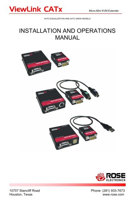
<strong>ViewLink</strong> <strong>CATx</strong> Micro-Mini KVM Extender<br />
AUTO EQUALIZATION AND AUTO SKEW MODELS<br />
INSTALLATION AND OPERATIONS<br />
MANUAL<br />
10707 Stancliff Road Phone: (281) 933-7673<br />
Houston, Texas www.rose.com
LIMITED WARRANTY<br />
<strong>Rose</strong> <strong>Electronics</strong> ® warrants the <strong>ViewLink</strong> <strong>CATx</strong> to be in good working order for one year from the date<br />
of purchase from <strong>Rose</strong> <strong>Electronics</strong> or an authorized dealer. Should this product fail to be in good working<br />
order at any time during this one-year warranty period, <strong>Rose</strong> <strong>Electronics</strong> will, at its option, repair or replace<br />
the Unit as set forth below. Repair parts and replacement units will be either reconditioned or new. All<br />
replaced parts become the property of <strong>Rose</strong> <strong>Electronics</strong>. This limited warranty does not include service to<br />
repair damage to the Unit resulting from accident, disaster, abuse, or unauthorized modification of the<br />
Unit, including static discharge and power surges.<br />
Limited Warranty service may be obtained by delivering this unit during the one-year warranty period to<br />
<strong>Rose</strong> <strong>Electronics</strong> or an authorized repair center providing a proof of purchase date. If this Unit is delivered<br />
by mail, you agree to insure the Unit or assume the risk of loss or damage in transit, to prepay shipping<br />
charges to the warranty service location, and to use the original shipping container or its equivalent. You<br />
must call for a return authorization number first. Under no circumstances will a unit be accepted without a<br />
return authorization number. Contact an authorized repair center or <strong>Rose</strong> <strong>Electronics</strong> for further<br />
information.<br />
ALL EXPRESS AND IMPLIED WARRANTIES FOR THIS PRODUCT INCLUDING THE WARRANTIES<br />
OF MERCHANTABILITY AND FITNESS FOR A PARTICULAR PURPOSE, ARE LIMITED IN DURATION<br />
TO A PERIOD OF ONE YEAR FROM THE DATE OF PURCHASE, AND NO WARRANTIES, WHETHER<br />
EXPRESS OR IMPLIED, WILL APPLY AFTER THIS PERIOD. SOME STATES DO NOT ALLOW<br />
LIMITATIONS ON HOW LONG AN IMPLIED WARRANTY LASTS, SO THE ABOVE LIMITATION MAY<br />
NOT APPLY TO YOU.<br />
IF THIS PRODUCT IS NOT IN GOOD WORKING ORDER AS WARRANTIED ABOVE, YOUR SOLE<br />
REMEDY SHALL BE REPLACEMENT OR REPAIR AS PROVIDED ABOVE. IN NO EVENT WILL ROSE<br />
ELECTRONICS BE LIABLE TO YOU FOR ANY DAMAGES INCLUDING ANY LOST PROFITS, LOST<br />
SAVINGS OR OTHER INCIDENTAL OR CONSEQUENTIAL DAMAGES ARISING OUT OF THE USE OF<br />
OR THE INABILITY TO USE SUCH PRODUCT, EVEN IF ROSE ELECTRONICS OR AN AUTHORIZED<br />
DEALER HAS BEEN ADVISED OF THE POSSIBILITY OF SUCH DAMAGES, OR FOR ANY CLAIM BY<br />
ANY OTHER PARTY.<br />
SOME STATES DO NOT ALLOW THE EXCLUSION OR LIMITATION OF INCIDENTAL OR<br />
CONSEQUENTIAL DAMAGES FOR CONSUMER PRODUCTS, SO THE ABOVE MAY NOT APPLY TO<br />
YOU. THIS WARRANTY GIVES YOU SPECIFIC LEGAL RIGHTS AND YOU MAY ALSO HAVE OTHER<br />
RIGHTS WHICH MAY VARY FROM STATE TO STATE.<br />
NOTE: This equipment has been tested and found to comply with the limits for a Class A digital device,<br />
pursuant to Part 15 of he FCC Rules. These limits are designed to provide reasonable protection against<br />
harmful interference when the equipment is operated in a commercial environment. This equipment<br />
generates, uses, and can radiate radio frequency energy and, if not installed and used in accordance with<br />
the instruction manual, may cause harmful interference to radio communications. Operation of this<br />
equipment in a residential area is likely to cause harmful interference in which case the user will be<br />
required to correct the interference at his own expense.<br />
IBM, AT, and PS/2 are trademarks of International Business Machines Corp. Microsoft and Microsoft<br />
Windows are registered trademarks of Microsoft Corp. Any other trademarks mentioned in this manual<br />
are acknowledged to be the property of the trademark owner.<br />
Copyright <strong>Rose</strong> <strong>Electronics</strong> 2006. All rights reserved.<br />
No part of this manual may be reproduced, stored in a retrieval system, or transcribed in any form or any means,<br />
electronic or mechanical, including photocopying and recording, without the prior written permission of <strong>Rose</strong><br />
<strong>Electronics</strong>.<br />
<strong>Rose</strong> <strong>Electronics</strong> Part # MAN-VLC5<br />
Printed In the United States of America - Revision 1.9
IC STATEMENTS, EU DECLARATION OF CONFORMITY<br />
EUROPEAN UNION DECLARATION OF CONFORMITY<br />
ACCORDING TO COUNCIL DIRECTIVE 89/336EEC & 73/23EEC<br />
This equipment complies with the<br />
requirements of the European EMC Directive<br />
89/336/EEC
Contents<br />
TABLE OF CONTENTS<br />
Quick Start guide .................................................................................................6<br />
Disclaimer ............................................................................................................1<br />
System introduction .............................................................................................1<br />
Features...............................................................................................................2<br />
Package contents ................................................................................................2<br />
Models .................................................................................................................3<br />
Installation............................................................................................................4<br />
Installing the Switch model –............................................................................4<br />
Installing the Video only model - ......................................................................4<br />
Operation .............................................................................................................5<br />
Keyboard Commands ..........................................................................................5<br />
Keyboard Commands - Country Codes...............................................................6<br />
Keyboard Commands – Skew Adjustment (Skew models only) .........................6<br />
Flash Utility features / procedure.........................................................................7<br />
TroubleShooting ................................................................................................10<br />
Maintenance and Repair....................................................................................11<br />
Technical Support..............................................................................................11<br />
Safety.................................................................................................................12<br />
Figures<br />
Figure 1. Quick Installation Diagram ...................................................................6<br />
Figure 2. Models ..................................................................................................3<br />
Figure 3. Monitor mounting bracket.....................................................................4<br />
Figure 4. Flash Scan Screen ...............................................................................8<br />
Figure 5. Flash Port Configuration.......................................................................8<br />
Figure 6. Flash scan ............................................................................................9<br />
Appendices<br />
Appendix A – Part Numbers ..............................................................................13<br />
Appendix B – Specifications ..............................................................................14<br />
Appendix C – Grounding ...................................................................................15<br />
Appendix D – Video Only Model........................................................................16<br />
Appendix E – DDC – EDID table acquisition procedure....................................16
QUICK START GUIDE<br />
Quick Start guide<br />
The <strong>ViewLink</strong> system consists of a transmitter unit that connects to the video,<br />
keyboard, and mouse ports on a PC, server, or to a KVM switch and a receiver<br />
unit that connects to a keyboard, monitor, and mouse. The transmitter and<br />
receiver units are connected together with up to 1,000 feet of solid <strong>CATx</strong> cable.<br />
The transmitter and receiver are available for PS/2, USB, or PS?-USB systems.<br />
This section briefly describes the installation procedures. Refer to the following<br />
steps and diagram to install your <strong>ViewLink</strong> Catx.<br />
Step #1 –Connect the Receiver unit to the keyboard, monitor, and mouse<br />
cables on your KVM station. Connect the provided power adapter to<br />
the Receiver unit’s power input jack.<br />
Step #2 –Connect the Transmitter unit to the keyboard, monitor, and mouse<br />
ports on your PC. Depending on your <strong>ViewLink</strong> <strong>CATx</strong> model, connect<br />
it to either the PS/2 (MiniDin6) or USB ports. If you are connecting to<br />
a KVM switch using the DB25 model, connect it to the KVM port on<br />
the switch.<br />
Step #3 –Connect the Receiver and Transmitter units together using up to<br />
1,000 feet of <strong>CATx</strong> cable (CAT5, 5e, or 6).<br />
Step #4 –Apply power to the KVM monitor, the Receiver unit, and boot your PC<br />
(turn on the KVM switch if using the DB25 model).<br />
When you initialize the extender, it automatically senses the cable distance<br />
between the transmitter and receiver unit, adjusts the compensation and sets<br />
up everything for you. Refer to the manual instructions for additional<br />
information.<br />
#1 Connect Receiver #2 Connect Transmitter<br />
KVM Station<br />
#3 Connect <strong>CATx</strong> Cable<br />
#4 Apply power<br />
(See Appendix C and D for grounding and video only models)<br />
Figure 1. Quick Installation Diagram<br />
PC<br />
or<br />
Switch
Disclaimer<br />
VIEWLINK CATX INSTALLATION AND OPERATIONS MANUAL<br />
INTRODUCTION<br />
While every precaution has been taken in the preparation of this manual, the<br />
manufacturer assumes no responsibility for errors or omissions. Neither does<br />
the manufacturer assume any liability for damages resulting from the use of the<br />
information contained herein. The manufacturer reserves the right to change<br />
the specifications, functions, or circuitry of the product without notice.<br />
The manufacturer cannot accept liability for damages due to misuse of the<br />
product or other circumstances outside the manufacturer’s control. The<br />
manufacturer will not be responsible for any loss, damage, or injury arising<br />
directly or indirectly from the use of this product.<br />
System introduction<br />
Thank you for choosing the <strong>Rose</strong> <strong>Electronics</strong> ® <strong>ViewLink</strong> <strong>CATx</strong> enhanced<br />
KVM extender. The <strong>ViewLink</strong> <strong>CATx</strong> is the result of <strong>Rose</strong> <strong>Electronics</strong><br />
commitment to providing state-of-the-art solutions for today’s demanding<br />
workplace. The <strong>ViewLink</strong> <strong>CATx</strong> has proven to be a valuable investment for any<br />
business, big or small, that has a need to access computers, servers, or KVM<br />
switches from remote locations. Using the <strong>ViewLink</strong> <strong>CATx</strong> to remotely access<br />
your computer has several applications that make it convenient for the users.<br />
You can locate your computers in a secure area and access them from other<br />
unsecured areas. Computers used in hazardous industrial environments can be<br />
accessed remotely, keeping the users safe and unexposed to any hazards.<br />
The <strong>ViewLink</strong> <strong>CATx</strong> system consists of two Units, a transmitter Unit and a<br />
receiver Unit. The transmitter connects easily to your computer or KVM switch.<br />
The receiver Unit connects to a remote keyboard, video monitor and a mouse.<br />
The transmitter and receiver units are connected together with industry<br />
standard CAT5, CAT5e, or CAT6 shielded or unshielded, solid core twisted-pair<br />
cable terminated with RJ45M connectors. All models can extend the distance<br />
from the CPU up to 1,000 feet. Applications can be executed; computer<br />
maintenance performed, and any function normally done can be performed with<br />
virtually no degradation in video quality and performance.<br />
Installation only takes a few minutes since the <strong>ViewLink</strong> <strong>CATx</strong> automatically<br />
sets up various parameters and functions based on your system topology.<br />
There are no jumpers to set or adjustment knobs to turn. Parameters like video<br />
gain and color skew are automatically compensated for and properly adjusted<br />
based on the length and type of <strong>CATx</strong> cable used. Some fine tuning can easily<br />
be done using keyboard commands, but are rarely needed.<br />
The only cable needed is a <strong>CATx</strong> cable to connect the transmitter to the<br />
receiver. <strong>CATx</strong> cable can be ordered from <strong>Rose</strong> <strong>Electronics</strong> in 25-1,000 foot<br />
lengths.<br />
1
Features<br />
� Available in automatic skew and non-skew models that connect to<br />
computers with PS/2 keyboard and mouse ports, computers with USB<br />
keyboard and mouse ports, or KVM switches with DB25F KVM ports<br />
� Extend a KVM station from a CPU using a single <strong>CATx</strong> cable<br />
� Resolution : Up to 1920 x 1440 @ 60Hz @ 300’<br />
1024 x 768 @ 60Hz @ 1,000’<br />
� <strong>ViewLink</strong> <strong>CATx</strong> uses a microprocessor to emulate the keyboard and mouse<br />
for plug and play operation. The keyboard and mouse on the receiver Unit<br />
do not have to be connected for the PC to boot; only the transmitter Unit<br />
must be connected to the PC<br />
� Compatible with <strong>Rose</strong> <strong>Electronics</strong> family of KVM switches such as<br />
ServeView Pro, UltraView Pro and UltraMatrix<br />
� Operating system independent<br />
� Status indicator LEDs on each RJ45 connector<br />
� All settings and video tuning are performed automatically. No user<br />
adjustments are needed to achieve a crystal clear display on the receiver<br />
KVM monitor. (Manual adjustments are available using special keyboard<br />
commands)<br />
Package contents<br />
The package contents consist of the following:<br />
� The <strong>ViewLink</strong> <strong>CATx</strong> transmitter and receiver units as ordered<br />
� Power adapter for receiver Unit<br />
� Installation and operations manual<br />
� PS/2 “Y” cable for receiver unit<br />
<strong>CATx</strong> and other cables are usually ordered separately. If the package contents<br />
are not correct, contact <strong>Rose</strong> <strong>Electronics</strong> or your reseller, so the problem can<br />
be quickly resolved.<br />
<strong>Rose</strong> <strong>Electronics</strong> web site<br />
Visit out web site at www.rose.com for additional information on the <strong>ViewLink</strong><br />
<strong>CATx</strong> and other products that are designed for data center applications,<br />
classroom environments and other applications.<br />
About this manual<br />
This manual covers the installation and operation of the <strong>ViewLink</strong> <strong>CATx</strong><br />
models.<br />
2 VIEWLINK CATX INSTALLATION AND OPERATIONS MANUAL
Models<br />
PS/2<br />
Video<br />
Only<br />
USB<br />
&<br />
Video<br />
Only<br />
Transmitters Receivers<br />
Transmitter with 2-PS/2 cables and 1-USB cable is available<br />
Figure 2. Models<br />
The PC model<br />
connects directly<br />
to the keyboard,<br />
monitor and<br />
mouse ports on<br />
a PC<br />
VIEWLINK CATX INSTALLATION AND OPERATIONS MANUAL<br />
MODELS<br />
The DB25<br />
model<br />
connects<br />
directly to the<br />
KVM port of a<br />
KVM switch<br />
The only cable needed to install the basic configuration of the <strong>ViewLink</strong> <strong>CATx</strong><br />
is the <strong>CATx</strong> cable that connects the transmitter to the receiver. Care should<br />
be used when routing the <strong>CATx</strong> cable. Avoid routing the cable close to<br />
machinery or electronic equipment. The electro-mechanical emissions may<br />
cause interference and undesirable video performance.<br />
3
INSTALLATION<br />
Installation<br />
Installing the <strong>ViewLink</strong> <strong>CATx</strong> is a very easy plug-and-play process. For the PC, PS/2<br />
and USB models simply connect the HD15M connector on the transmitter to the<br />
HD15F video out connector on the PC. Connect the PS/2 or USB keyboard and<br />
mouse cables to the corresponding connector ports on the PC. Connect the receiver<br />
directly to the keyboard, monitor, and mouse cables used for the KVM station.<br />
Connect the power adapter to the receiver unit’s power port. Finally, connect the<br />
transmitter’s RJ45 connector to the receiver’s RJ45 connector using up to 1,000 feet of<br />
<strong>CATx</strong> cable.<br />
If you are using a flat panel monitor, <strong>Rose</strong> <strong>Electronics</strong> has designed a universal<br />
mounting bracket that can be attached to any edge of a receiver unit and secured to<br />
the back of a flat panel monitor. An example of using this bracket is shown below.<br />
The bracket can be mounted vertically (as shown) or horizontally.<br />
Figure 3. Monitor mounting bracket<br />
NOTE: See Appendix C and D for proper grounding and video only installation<br />
Installing the Switch model –<br />
For the Switch DB25 model, connect the transmitter’s DB25M connector to a KVM<br />
switch’s DB25F KVM input connector. Connect the receiver directly to the keyboard,<br />
monitor, and mouse cables used for the KVM station. Connect the power adapter to<br />
the receiver unit’s power port. Finally, connect the transmitter’s RJ45 connector to the<br />
receiver’s RJ45 connector using up to 1,000 feet of <strong>CATx</strong> cable.<br />
NOTE1: Distance will vary depending on resolution used<br />
NOTE2: See Appendix “E” for DDC – EDID acquisition procesure<br />
Installing the Video only model -<br />
For the Video only model, connect the transmitter’s HD15M connector to the<br />
HD15F video out connector on the PC. Connect the transmitter’s USB cable to the<br />
computers USB port. The USB cable provides power only to the transmitter.<br />
Connect the receiver’s HD15F connector to a video monitor and connect the power<br />
adapter. If a USB port is not available, <strong>Rose</strong> <strong>Electronics</strong> can provide a special cable to<br />
connect to transmitter to a power adapter. See part number table.<br />
NOTE: The USB ports on the receiver are for connecting a USB keyboard to perform<br />
video adjustments only. (Commands shown on page 5)<br />
4 VIEWLINK CATX INSTALLATION AND OPERATIONS MANUAL
No user adjustments are needed. The <strong>ViewLink</strong> <strong>CATx</strong> will automatically determine the<br />
<strong>CATx</strong> cable length between the transmitter and receiver and automatically adjust the<br />
gain to compensate for the calculated cable length. If needed, keyboard commands can<br />
be issued to fine tune the video gain and equalization.<br />
Apply power to the receiver unit, KVM monitor, and boot the PC. The monitor connected<br />
to the receiver unit will display a clear, clean image of the boot sequence.<br />
Operation<br />
Operation of your system is no different than having your keyboard, monitor, and mouse<br />
connected directly to a PC or KVM switch. The only difference is they can be up to<br />
1,000 feet away. You can operate your system normally, programs can be executed,<br />
maintenance can be performed, and any operation normally performed can be done with<br />
no derogation in video quality and performance.<br />
Keyboard Commands<br />
Command Description<br />
Left Ctrl, Left Shift, e: Perform a cable length measurement<br />
Left Ctrl, Left Shift,<br />
keyboard +:<br />
Left Ctrl, Left Shift,<br />
keyboard -:<br />
Left Ctrl, Left Shift,<br />
keypad +:<br />
Left Ctrl, Left Shift,<br />
keypad -:<br />
Increase the video gain by 1<br />
Decrease the video gain by 1.<br />
increase the video equalization by 1<br />
Decrease the video equalization by 1<br />
Left Ctrl, Left Shift, k Saves any changes made<br />
Left Ctrl, Left Shift, i*<br />
(See * Below)<br />
Left Ctrl, Left Shift, g*<br />
(See * Below)<br />
Sends Transmitter, CPLD, and receiver firmware version to a<br />
text editor on the CPU the unit is connected. Firmware is<br />
reported as follows:<br />
Transmitter = hxxy,<br />
CPLD = yx,<br />
Receiver = dxxy:<br />
Where x is a decimal digit, and y is an alphabetic character<br />
Send the most recent gain, equalization, cable length, autotdr<br />
status, red, green, and blue skew values to a text editor.<br />
* CAUTION: DO NOT EXECUTE THESE COMMANDS WITHOUT A TEXT<br />
EDITOR ACTIVE. A text editor such as notepad must be started and selected<br />
prior to executing these keyboard commands.<br />
VIEWLINK CATX INSTALLATION AND OPERATIONS MANUAL<br />
5
Keyboard Commands - Country Codes<br />
The following country code table allows you to enter the country code for type of<br />
keyboard and operating system used. This function is only required if your<br />
operating system is country specific and requires that a keyboard map specific for<br />
your operating system be entered. Sun Japanese keyboards and others that require<br />
this should enter their country code.<br />
To enter the country code, enter the following key sequence:<br />
Lctrl, Lshift, l, x, Enter, (non-cap L, x)<br />
or<br />
Lctrl, Lshift, l, x, y, Enter,<br />
where X and Y are keyboard numeric keys.<br />
If the country code number is a single digit (0-9), enter one digit (or two digits,<br />
ie.06), followed by enter. If the country code is a double digit (10-35), enter both<br />
numbers, followed by enter. Each key is pressed and released, and no more than 2<br />
seconds can elapse between any two keys of the sequence, or the command will<br />
abort. The command only has to be entered once. <strong>ViewLink</strong> CAT5 KVM Extender<br />
saves the value in flash. The entered value does not change if the unit is flashed<br />
with new code.<br />
Code Country Code Country Code Country<br />
00 Not Supported 13 International (ISO) 25 Spanish<br />
01 Arabic 14 Italian 26 Swedish<br />
02 Belgian 15 Japan (Katakana) 27 Swiss/French<br />
03 Canadian-Bilingual 16 Korean 28 Swiss/German<br />
04 Canadian-French 17 Latin American 29 Switzerland<br />
05 Czech Republic 18 Netherlands/Dutch 30 Taiwan<br />
06 Danish 19 Norwegian 31 Turkish-Q<br />
07 Finnish 20 Persian (Farsi) 32 UK<br />
08 French 21 Poland 33 US<br />
09 German 22 Portuguese 34 Yugoslavia<br />
10 Greek 23 Russia 35 Turkish-F<br />
11 Hebrew 24 Slovakia 36-255 Reserved<br />
12 Hungary<br />
Keyboard Commands – Skew Adjustment (Skew models only)<br />
Command Function<br />
Left Ctrl + Left Shift + 1 Increase RED skew by one unit<br />
Left Ctrl + Left Shift + 2 Decrease RED skew by one unit<br />
Left Ctrl + Left Shift + 3 Increase Green skew by one unit<br />
Left Ctrl + Left Shift + 4 Decrease Green skew by one unit<br />
Left Ctrl + Left Shift + 5 Increase Blue skew by one unit<br />
Left Ctrl + Left Shift + 6 Decrease Blue skew by one unit<br />
When adjustments are complete, save the changes (Left ctrl + left shift + k)<br />
6 VIEWLINK CATX INSTALLATION AND OPERATIONS MANUAL
Flash Utility features / procedure<br />
FLASH PROCEDURE<br />
The <strong>ViewLink</strong> Catx was designed to easily keep up with the ever changing<br />
electronic world. The flash feature of the <strong>ViewLink</strong> <strong>CATx</strong> means the product will<br />
always be up to date with new technologies, features, and enhancements.<br />
Updating the flash memory is an easy process using <strong>Rose</strong>’s flash utility. The<br />
universal flash utility is easily installed and can be used on a variety of <strong>Rose</strong><br />
products. When executed, the flash program will automatically detect the<br />
product type to flash, validate the connections, and verify the product firmware<br />
version.<br />
To flash update the <strong>ViewLink</strong> <strong>CATx</strong> firmware you will need the flash utility<br />
program and the firmware update file. The flash utility and current firmware file<br />
for the <strong>ViewLink</strong> <strong>CATx</strong> can be downloaded from our web site at<br />
www.rose.com/htm/download.htm.<br />
After downloading the flash utility program and the firmware update file,<br />
execute the program “Setup<strong>Rose</strong>KVMUtil-x_xx.exe” (x_xx = version level)<br />
to install the flash utility program. Installation and set-up follow the standard<br />
Windows ® installation procedure. Follow the on-screen instructions to properly<br />
install the flash utility.<br />
When installation of the flash utility is complete, connect the <strong>ViewLink</strong> <strong>CATx</strong><br />
receiver unit’s RJ45F (Link) connector to the serial port (Com1/DB9M) on the<br />
PC the flash utility program was installed on using the flash utility cable<br />
(RJ45M to DB9F cable, P/N CAB-ATRF). Connect the power adapter to the<br />
<strong>ViewLink</strong> <strong>CATx</strong> receiver unit and apply power.<br />
With all cable connections in place and the flash utility installed, execute the<br />
flash program “…\<strong>Rose</strong> <strong>Electronics</strong> KVM Utility\KVMUtility.exe”. Depending on<br />
the installation options chosen, you can execute the utility by clicking on the<br />
<strong>Rose</strong> <strong>Electronics</strong> KVM Utility Icon from the desktop, Start Menu, or Quick Start<br />
toolbar. The utility program, when executed, will automatically start scanning<br />
for a connected supported <strong>Rose</strong> product (<strong>ViewLink</strong> <strong>CATx</strong> receiver). The utility<br />
program will automatically start scanning COM1 and the PS/2 port for a<br />
supported device. If a supported device is not found on COM1 or the PS/2<br />
port, the program will display the information shown in Figure 4 To exit, press<br />
any key.<br />
If the product has been connected to a port other than COM1, don’t exit the<br />
utility program but modify the port to scan by clicking on “File” then “Scan for<br />
Device On”. Next, click on the down arrow(s) to select a different COM port or<br />
change the serial parameters as shown in Figure 5.<br />
VIEWLINK CATX INSTALLATION AND OPERATIONS MANUAL<br />
7
Figure 4. Flash Scan Screen<br />
Figure 5. Flash Port Configuration<br />
8 VIEWLINK CATX INSTALLATION AND OPERATIONS MANUAL
Upon successfully scanning and identifying a supported device, the detected<br />
information shown in Figure 6 will display showing the product type and the port<br />
it is connected to. The <strong>ViewLink</strong> <strong>CATx</strong> is ready to flash with the new firmware.<br />
Figure 6. Flash scan<br />
To load the updated firmware to the <strong>ViewLink</strong> <strong>CATx</strong>, click on “File”, then “Load<br />
New Firmware”. Select the downloaded firmware update file to load. This will<br />
be a file with .hex file extension. Error! Reference source not found. show<br />
the flash update screen which shows the progress and, when finished, the<br />
status of the flash process. When the message “New firmware successfully<br />
loaded on device” displays, the <strong>ViewLink</strong> <strong>CATx</strong> product is updated and ready to<br />
use with the updated firmware.<br />
VIEWLINK CATX INSTALLATION AND OPERATIONS MANUAL<br />
9
TROUBLESHOOTING<br />
TroubleShooting<br />
The troubleshooting section is used as a guide to understanding the capabilities<br />
of the <strong>ViewLink</strong> <strong>CATx</strong> and for general troubleshooting. If you have any<br />
problems or questions concerning the installation, operation or usage of the<br />
<strong>ViewLink</strong> <strong>CATx</strong> that is not covered in this manual, please contact <strong>Rose</strong><br />
<strong>Electronics</strong> for technical support.<br />
• No video on the receiver monitor<br />
o Check <strong>CATx</strong> connection at the receiver, transmitter, patch panels (if<br />
applicable)<br />
o Check HD15 video connection at the receiver and transmitter<br />
o Verify video is present at the video card output<br />
• Keyboard has no effect<br />
o Keyboard and mouse cables reversed at the PC<br />
o Check keyboard cable connection at the Receiver<br />
• Mouse erratic or not functioning<br />
o Mouse and keyboard cables reversed at the PC<br />
o Check mouse cable connection at the Receiver<br />
• No video, keyboard or mouse functions<br />
o Check all cable connection at the Receiver<br />
o Check all cable connections at the Transmitter<br />
o Check RJ45 connector LEDs. If the green and yellow LEDs are<br />
alternately flashing, the firmware has become corrupt and the unit must<br />
be flashed. This can occur if a power loss occurs during the flash<br />
procedure.<br />
10 VIEWLINK CATX INSTALLATION AND OPERATIONS MANUAL
Maintenance and Repair<br />
SERVICE and SUPPORT<br />
This Unit does not contain any internal user-serviceable parts. In the event a<br />
Unit needs repair or maintenance, you must first obtain a Return Authorization<br />
(RA) number from <strong>Rose</strong> <strong>Electronics</strong> or an authorized repair center. This Return<br />
Authorization number must appear on the outside of the shipping container.<br />
See Limited Warranty for more information.<br />
When returning a Unit, it should be double-packed in the original container or<br />
equivalent, insured and shipped to:<br />
<strong>Rose</strong> <strong>Electronics</strong><br />
Attn: RA__________<br />
10707 Stancliff Road<br />
Houston, Texas 77099 USA<br />
Technical Support<br />
If you are experiencing problems, or need assistance in setting up, configuring,<br />
or operating your CrystalView Plus, consult the appropriate sections of this<br />
manual. If, however, you require additional information or assistance, please<br />
contact the <strong>Rose</strong> <strong>Electronics</strong> Technical Support Department at:<br />
Phone: (281) 933-7673<br />
E-Mail: TechSupport@rose.com<br />
Web: www.rose.com<br />
Technical Support hours are from: 8:00 am to 6:00 pm CST (USA), Monday<br />
through Friday.<br />
Please report any malfunctions in the operation of this Unit or any<br />
discrepancies in this manual to the <strong>Rose</strong> <strong>Electronics</strong> Technical Support<br />
Department.<br />
VIEWLINK CATX INSTALLATION AND OPERATIONS MANUAL<br />
11
SAFETY<br />
Safety<br />
The <strong>ViewLink</strong> <strong>CATx</strong> KVM extender has been tested for conformance to safety<br />
regulations and requirements, and has been certified for international use. Like<br />
all electronic equipment, the <strong>ViewLink</strong> <strong>CATx</strong> should be used with care. To<br />
protect yourself from possible injury and to minimize the risk of damage to the<br />
Unit, read and follow these safety instructions.<br />
� Follow all instructions and warnings marked on this Unit.<br />
� Except where explained in this manual, do not attempt to service this Unit<br />
yourself.<br />
� Do not use this Unit near water.<br />
� Provide proper ventilation and air circulation.<br />
� Keep power cord and connection cables clear of obstructions that might<br />
cause damage to them.<br />
� Use only power cords and connection cables designed for this Unit.<br />
� Use only a grounded (three-wire) electrical outlet.<br />
� Use only the power adapter provided with the <strong>ViewLink</strong> <strong>CATx</strong>.<br />
� Keep objects that might damage this Unit and liquids that may spill, clear<br />
from this Unit. Liquids and foreign objects might come in contact with<br />
voltage points that could create a risk of fire or electrical shock.<br />
� Operate this Unit only when the cover is in place.<br />
� Do not use liquid or aerosol cleaners to clean this Unit. Always unplug this<br />
Unit from its electrical outlet before cleaning.<br />
� Unplug this Unit from the electrical outlet and refer servicing to a qualified<br />
service center if any of the following conditions occur:<br />
o The power cord or connection cables are damaged or frayed.<br />
o The Unit has been exposed to any liquids.<br />
o The Unit does not operate normally when all operating instructions<br />
have been followed.<br />
o The Unit has been dropped or the case has been damaged.<br />
o The Unit exhibits a distinct change in performance, indicating a need<br />
for service.<br />
12 VIEWLINK CATX INSTALLATION AND OPERATIONS MANUAL
Appendix A – Part Numbers<br />
Transmitter P/N Description<br />
VLT-MVP Single access, PS/2, VGA<br />
VLT-MVU Single access, USB, VGA<br />
VLT-MVB Single access, PS2 & USB, VGA<br />
VLT-MV0 VGA only<br />
Receiver P/N Description<br />
VLR-AVP Single access, PS/2, VGA<br />
VLR-AVU Single access, USB, VGA<br />
VLR-AV0 VGA only<br />
Kit P/N Description<br />
VLK-TMVPRAVP Single access PS/2, VGA<br />
VLK-TMVURAVU Single access USB, VGA<br />
VLK-TMVBRAVP Single access, PS/2 & USB to PS/2, VGA<br />
VLK-TMVBRAVU Single access, PS/2 & USB to USB, VGA<br />
-W option = Auto Skew compensation<br />
Cables Description<br />
CAB-08C5UTPnnn CAT5 unshieded twisted pair<br />
CAB-08C6UTPnnn CAT6 unshieded twisted pair<br />
CAB-08C5STPnnn CAT5 shieded twisted pair<br />
CAB-08C6STPnnn CAT6 shieded twisted pair<br />
CAB-ATRFnnn DB9F to RJ45M flash utility cable<br />
VIEWLINK CATX INSTALLATION AND OPERATIONS MANUAL<br />
APPENDICES<br />
USB to Barrel jack auxiliary power for transmitter<br />
ACC-MD6M2MD6F PS/2 “Y” cable for receiver<br />
Power Adapter Description<br />
TFR-05D250FSUB-1.3A Power Adapter for Receiver units<br />
CAB-PWR6/C7/US Power cord for Power adapter (Ordered separately)<br />
13
Appendix B – Specifications<br />
Dimensions Width Depth Height<br />
Transmitter (in / cm)<br />
Transmitter*(in / cm)<br />
1.3 / 33<br />
2.17 / 5.5<br />
1.65 / 42<br />
2.52 / 6.4<br />
0.63 / 1.6<br />
0.72 / 1.8<br />
Receiver (in / cm) 2.2 / 56 2.56 / 65 0.83 / 21<br />
* DB25 Transmitter model<br />
Video:<br />
Resolution: Up to 1920 x 1440 @ 60Hz @ 300’<br />
1024 x 768 @ 60Hz @ 1,000’<br />
Compatibility: SVGA, VGA, XGA, RGB<br />
Levels: 0.7V p-p<br />
Sync type: Separate/composite TTL level<br />
Support:<br />
Keyboards: PS/2, USB<br />
Video: VGA, SVGA, XGA, RGB<br />
Mouse: PS/2 two button<br />
Microsoft Compatible Mouse<br />
Logitech Compatible Mouse<br />
USB<br />
Connectors:<br />
PS/2 model: Video HD15F<br />
Keyboard PS/2<br />
Mouse PS/2<br />
USB model: Video HD15F<br />
Keyboard USB type A<br />
Mouse USB type A<br />
PS/2 & USB model has 2-PS/2 and 1-USB cable<br />
Interconnect: <strong>CATx</strong> UTP/STP, EIA / (CAT5, 5e, 6) TIA 568<br />
Power: Local From PC (Optional power adapter)<br />
Remote + 5V 1.0A external<br />
Environmental: Temp. 0°C – 45°C (32°F – 113°F)<br />
Humidity 0% – 90% non-condensing<br />
Approvals: CE<br />
14 VIEWLINK CATX INSTALLATION AND OPERATIONS MANUAL
Appendix C – Grounding<br />
This unit is designed to operate properly when connected to a desktop<br />
computer with a common earth ground to all equipment. When using this<br />
product on a laptop computer there may be video problems due to the laptop<br />
not being tied to earth ground. To clear up the video, the product must be<br />
physically connected to an earth ground connector.<br />
Transmitter<br />
Receiver<br />
Install a lug connector that fits the<br />
thumb screws as shown and secure<br />
the <strong>ViewLink</strong> Catx to the computer’s<br />
video port with the lug between the<br />
<strong>ViewLink</strong> Catx and the computer’s<br />
chassis. Connect the other end of<br />
the grounding wire to an earth<br />
ground connector. This will<br />
establish a common earth ground<br />
between the laptop, the <strong>ViewLink</strong><br />
Catx transmitter and other<br />
equipment. The video should<br />
display properly<br />
Remove the HD15 connectors<br />
mounting hardware as shown<br />
and install a lug connector that<br />
fits the threads and secure the<br />
connector back to the HD15<br />
connector mounting position.<br />
Connect the other end of the<br />
grounding wire to an earth<br />
ground connector. This will<br />
establish a common earth ground<br />
between the <strong>ViewLink</strong> Catx<br />
receiver and other equipment.<br />
VIEWLINK CATX INSTALLATION AND OPERATIONS MANUAL<br />
15
Appendix D – Video Only Model<br />
Video Only Models<br />
Video only models should be connected as shown below. To obtain power and<br />
also power to a local keyboard for video adjustments, connect the provided<br />
PS/2 “Y” cable to:<br />
� Your computer’s PS/2 keyboard connector<br />
� Connect one PS/2 cable connector the unit<br />
� Connect the other PS/2 cable connector to the PS/2 cable from a keyboard.<br />
� Ground the transmitter and receiver if necessary<br />
Receiver<br />
Remote monitor<br />
Transmitter<br />
Local PS/2 Keyboard<br />
“Y” Cable<br />
Appendix E – DDC – EDID table acquisition procedure<br />
When power is first applied to the remote monitor and the receiver unit, the<br />
DDC – EDID table information is acquired from the monitor connected to the<br />
receiver unit. The receiver unit sends this information to the transmitter each<br />
time a link is established. If the sent DDC – EDID table does not match the one<br />
saved in the transmitter, the new table is saved to the transmitter’s flash<br />
memory.<br />
When the PC is booted, it obtains the DDC – EDID information table from the<br />
transmitter unit. This information is obtained only once when the PC is booted.<br />
The following initial power up procedure should be followed:<br />
1- Connect all cabling and turn on the remote monitor.<br />
2- Apply power to the receiver unit.<br />
3- Boot the PC (power to the transmitter is applied when power is applied<br />
to the computer.<br />
When replacing the remote monitor, the same power up procedure should be<br />
followed.<br />
16 VIEWLINK CATX INSTALLATION AND OPERATIONS MANUAL
10707 Stancliff Road Phone: (281) 933-7673<br />
Houston, Texas 77099 WWW.ROSE.COM