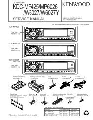
SERVICE MANUAL - Page de test
SERVICE MANUAL - Page de test
SERVICE MANUAL - Page de test

You also want an ePaper? Increase the reach of your titles
YUMPU automatically turns print PDFs into web optimized ePapers that Google loves.
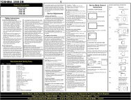
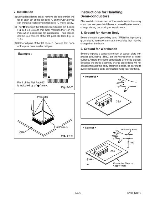
2. Installation<br />
(1) Using <strong>de</strong>sol<strong>de</strong>ring braid, remove the sol<strong>de</strong>r from the<br />
foil of each pin of the flat pack-IC on the CBA so you<br />
can install a replacement flat pack-IC more easily.<br />
(2) The “ ” mark on the flat pack-IC indicates pin 1. (See<br />
Fig. S-1-7.) Be sure this mark matches the 1 on the<br />
PCB when positioning for installation. Then presol<strong>de</strong>r<br />
the four corners of the flat pack-IC. (See Fig. S-<br />
1-8.)<br />
(3) Sol<strong>de</strong>r all pins of the flat pack-IC. Be sure that none<br />
of the pins have sol<strong>de</strong>r bridges.<br />
Example :<br />
Instructions for Handling<br />
Semi-conductors<br />
Electrostatic breakdown of the semi-conductors may<br />
occur due to a potential difference caused by electrostatic<br />
charge during unpacking or repair work.<br />
1. Ground for Human Body<br />
Be sure to wear a grounding band (1MΩ) that is properly<br />
groun<strong>de</strong>d to remove any static electricity that may be<br />
charged on the body.<br />
2. Ground for Workbench<br />
Be sure to place a conductive sheet or copper plate with<br />
proper grounding (1MΩ) on the workbench or other<br />
surface, where the semi-conductors are to be placed.<br />
Because the static electricity charge on clothing will not<br />
escape through the body grounding band, be careful to<br />
avoid contacting semi-conductors with your clothing.<br />
< Incorrect ><br />
Pin 1 of the Flat Pack-IC<br />
is indicated by a " " mark.<br />
Fig. S-1-7<br />
Presol<strong>de</strong>r<br />
CBA<br />
CBA<br />
Flat Pack-IC<br />
Fig. S-1-8<br />
< Correct ><br />
Grounding Band<br />
CBA<br />
Conductive Sheet or<br />
Copper Plate<br />
1-4-3 DVD_NOTE