(ISSI) (PDF) - Integrated Silicon Solution, Inc
(ISSI) (PDF) - Integrated Silicon Solution, Inc
(ISSI) (PDF) - Integrated Silicon Solution, Inc

Create successful ePaper yourself
Turn your PDF publications into a flip-book with our unique Google optimized e-Paper software.
IS42S86400B<br />
IS42S16320B, IS45S16320B<br />
64M x 8, 32M x 16<br />
512Mb SYNCHRONOUS DRAM DECEMBER 2011<br />
FEATURES<br />
• Clock frequency: 166, 143, 133 MHz<br />
• Fully synchronous; all signals referenced to a<br />
positive clock edge<br />
• Internal bank for hiding row access/precharge<br />
• Power supply<br />
Vdd<br />
Vddq<br />
IS42/45S16320B 3.3V 3.3V<br />
IS42S86400B 3.3V 3.3V<br />
• LVTTL interface<br />
• Programmable burst length<br />
– (1, 2, 4, 8, full page)<br />
• Programmable burst sequence:<br />
Sequential/Interleave<br />
• Auto Refresh (CBR)<br />
• Self Refresh<br />
• 8K refresh cycles every 16ms (A2 grade) or<br />
64 ms (Commercial, Industrial, A1 grade)<br />
• Random column address every clock cycle<br />
• Programmable CAS latency (2, 3 clocks)<br />
• Burst read/write and burst read/single write<br />
operations capability<br />
• Burst termination by burst stop and precharge<br />
command<br />
• Available in 54-pin TSOP-II and 54-ball W-BGA<br />
(x16 only)<br />
• Operating Temperature Range:<br />
Commercial: 0 o C to +70 o C<br />
Industrial: -40 o C to +85 o C<br />
Automotive, A1: -40 o C to +85 o C<br />
Automotive, A2: -40 o C to +105 o C<br />
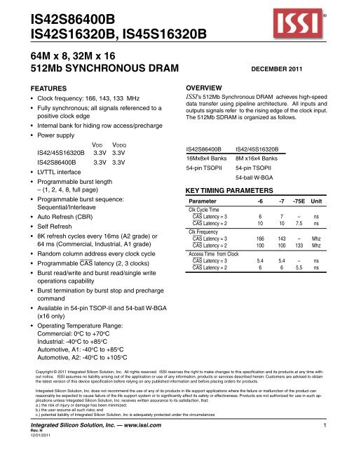
OVERVIEW<br />
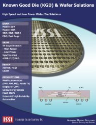
<strong>ISSI</strong>'s 512Mb Synchronous DRAM achieves high-speed<br />
data transfer using pipeline architecture. All inputs and<br />
outputs signals refer to the rising edge of the clock input.<br />
The 512Mb SDRAM is organized as follows.<br />
IS42S86400B<br />
16Mx8x4 Banks<br />
54-pin TSOPII<br />
IS42/45S16320B<br />
8M x16x4 Banks<br />
54-pin TSOPII<br />
54-ball W-BGA<br />
KEY TIMING PARAMETERS<br />
Parameter -6 -7 -75E Unit<br />
Clk Cycle Time<br />
CAS Latency = 3 6 7 – ns<br />
CAS Latency = 2 10 10 7.5 ns<br />
Clk Frequency<br />
CAS Latency = 3 166 143 – Mhz<br />
CAS Latency = 2 100 100 133 Mhz<br />
Access Time from Clock<br />
CAS Latency = 3 5.4 5.4 – ns<br />
CAS Latency = 2 6 6 5.5 ns<br />
Copyright © 2011 <strong>Integrated</strong> <strong>Silicon</strong> <strong>Solution</strong>, <strong>Inc</strong>. All rights reserved. <strong>ISSI</strong> reserves the right to make changes to this specification and its products at any time without<br />
notice. <strong>ISSI</strong> assumes no liability arising out of the application or use of any information, products or services described herein. Customers are advised to obtain<br />
the latest version of this device specification before relying on any published information and before placing orders for products.<br />
<strong>Integrated</strong> <strong>Silicon</strong> <strong>Solution</strong>, <strong>Inc</strong>. does not recommend the use of any of its products in life support applications where the failure or malfunction of the product can<br />
reasonably be expected to cause failure of the life support system or to significantly affect its safety or effectiveness. Products are not authorized for use in such applications<br />
unless <strong>Integrated</strong> <strong>Silicon</strong> <strong>Solution</strong>, <strong>Inc</strong>. receives written assurance to its satisfaction, that:<br />
a.) the risk of injury or damage has been minimized;<br />
b.) the user assume all such risks; and<br />
c.) potential liability of <strong>Integrated</strong> <strong>Silicon</strong> <strong>Solution</strong>, <strong>Inc</strong> is adequately protected under the circumstances<br />
<strong>Integrated</strong> <strong>Silicon</strong> <strong>Solution</strong>, <strong>Inc</strong>. — www.issi.com 1<br />
Rev. H<br />
12/01/2011
IS42S86400B, IS42/45S16320B<br />
DEVICE OVERVIEW<br />
The 512Mb SDRAM is a high speed CMOS, dynamic<br />
random-access memory designed to operate in 3.3V Vdd<br />
and 3.3V Vddq memory systems containing 536,870,912<br />
bits. Internally configured as a quad-bank DRAM with a<br />
synchronous interface. Each 134,217,728-bit bank is organized<br />
as 8,192 rows by 1024 columns by 16 bits. Each<br />
of the x8's 134,217,728-bit banks is organized as 8,192<br />
rows by 2048 columns by 8 bits.<br />
The 512Mb SDRAM includes an AUTO REFRESH MODE,<br />
and a power-saving, power-down mode. All signals are<br />
registered on the positive edge of the clock signal, CLK.<br />
All inputs and outputs are LVTTL compatible.<br />
The 512Mb SDRAM has the ability to synchronously burst<br />
data at a high data rate with automatic column-address<br />
generation, the ability to interleave between internal banks<br />
to hide precharge time and the capability to randomly<br />
change column addresses on each clock cycle during<br />
burst access.<br />
A self-timed row precharge initiated at the end of the burst<br />
sequence is available with the AUTO PRECHARGE function<br />
enabled. Precharge one bank while accessing one of the<br />
other three banks will hide the precharge cycles and provide<br />
seamless, high-speed, random-access operation.<br />
SDRAM read and write accesses are burst oriented starting<br />
at a selected location and continuing for a programmed<br />
number of locations in a programmed sequence. The<br />
registration of an ACTIVE command begins accesses,<br />
followed by a READ or WRITE command. The ACTIVE<br />
command in conjunction with address bits registered are<br />
used to select the bank and row to be accessed (BA0,<br />
BA1 select the bank; A0-A12 select the row). The READ<br />
or WRITE commands in conjunction with address bits<br />
registered are used to select the starting column location<br />
for the burst access.<br />
Programmable READ or WRITE burst lengths consist of<br />
1, 2, 4 and 8 locations or full page, with a burst terminate<br />
option.<br />
FUNCTIONAL BLOCK DIAGRAM (For 8MX16X4 Banks SHOWN)<br />
CLK<br />
CKE<br />
CS<br />
RAS<br />
CAS<br />
WE<br />
COMMAND<br />
DECODER<br />
&<br />
CLOCK<br />
GENERATOR<br />
MODE<br />
REGISTER<br />
REFRESH<br />
CONTROLLER<br />
16<br />
DATA IN<br />
BUFFER<br />
16<br />
2<br />
DQML<br />
DQMH<br />
DQ 0-15<br />
A10<br />
A12<br />
A11<br />
A9<br />
A8<br />
A7<br />
A6<br />
A5<br />
A4<br />
A3<br />
A2<br />
A1<br />
A0<br />
BA0<br />
BA1<br />
13<br />
ROW<br />
ADDRESS<br />
LATCH<br />
13<br />
MULTIPLEXER<br />
13<br />
SELF<br />
REFRESH<br />
CONTROLLER<br />
REFRESH<br />
COUNTER<br />
ROW<br />
ADDRESS<br />
BUFFER<br />
13<br />
ROW DECODER<br />
DATA OUT<br />
BUFFER<br />
16 16<br />
8192<br />
8192<br />
8192<br />
8192<br />
MEMORY CELL<br />
ARRAY<br />
BANK 0<br />
SENSE AMP I/O GATE<br />
VDD/VDDQ<br />
Vss/VssQ<br />
10<br />
COLUMN<br />
ADDRESS LATCH<br />
BANK CONTROL LOGIC<br />
1024<br />
(x 16)<br />
BURST COUNTER<br />
COLUMN<br />
ADDRESS BUFFER<br />
10<br />
COLUMN DECODER<br />
2 <strong>Integrated</strong> <strong>Silicon</strong> <strong>Solution</strong>, <strong>Inc</strong>. — www.issi.com<br />
Rev. H<br />
12/01/2011
IS42S86400B, IS42/45S16320B<br />
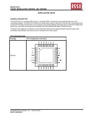
PIN CONFIGURATIONS<br />
54 pin TSOP - Type II for x8<br />
VDD<br />
DQ0<br />
VDDQ<br />
NC<br />
DQ1<br />
VSSQ<br />
NC<br />
DQ2<br />
VDDQ<br />
NC<br />
DQ3<br />
VSSQ<br />
NC<br />
VDD<br />
NC<br />
WE<br />
CAS<br />
RAS<br />
CS<br />
BA0<br />
BA1<br />
A10<br />
A0<br />
A1<br />
A2<br />
A3<br />
VDD<br />
1<br />
2<br />
3<br />
4<br />
5<br />
6<br />
7<br />
8<br />
9<br />
10<br />
11<br />
12<br />
13<br />
14<br />
15<br />
16<br />
17<br />
18<br />
19<br />
20<br />
21<br />
22<br />
23<br />
24<br />
25<br />
26<br />
27<br />
54<br />
53<br />
52<br />
51<br />
50<br />
49<br />
48<br />
47<br />
46<br />
45<br />
44<br />
43<br />
42<br />
41<br />
40<br />
39<br />
38<br />
37<br />
36<br />
35<br />
34<br />
33<br />
32<br />
31<br />
30<br />
29<br />
28<br />
VSS<br />
DQ7<br />
VSSQ<br />
NC<br />
DQ6<br />
VDDQ<br />
NC<br />
DQ5<br />
VSSQ<br />
NC<br />
DQ4<br />
VDDQ<br />
NC<br />
VSS<br />
NC<br />
DQM<br />
CLK<br />
CKE<br />
A12<br />
A11<br />
A9<br />
A8<br />
A7<br />
A6<br />
A5<br />
A4<br />
VSS<br />
PIN DESCRIPTIONS<br />
A0-A12<br />
A0-A9, A11<br />
BA0, BA1<br />
DQ0 to DQ7<br />
CLK<br />
CKE<br />
CS<br />
RAS<br />
Row Address Input<br />
Column Address Input<br />
Bank Select Address<br />
Data I/O<br />
System Clock Input<br />
Clock Enable<br />
Chip Select<br />
Row Address Strobe Command<br />
WE<br />
DQM<br />
Vdd<br />
Vss<br />
Vddq<br />
Vssq<br />
NC<br />
Write Enable<br />
Data Input/Output Mask<br />
Power<br />
Ground<br />
Power Supply for I/O Pin<br />
Ground for I/O Pin<br />
No Connection<br />
CAS<br />
Column Address Strobe Command<br />
<strong>Integrated</strong> <strong>Silicon</strong> <strong>Solution</strong>, <strong>Inc</strong>. — www.issi.com 3<br />
Rev. H<br />
12/01/2011
IS42S86400B, IS42/45S16320B<br />
PIN CONFIGURATIONS<br />
54 pin TSOP - Type II for x16<br />
VDD<br />
1<br />
54<br />
VSS<br />
DQ0<br />
2<br />
53<br />
DQ15<br />
VDDQ<br />
3<br />
52<br />
VSSQ<br />
DQ1<br />
4<br />
51<br />
DQ14<br />
DQ2<br />
5<br />
50<br />
DQ13<br />
VSSQ<br />
6<br />
49<br />
VDDQ<br />
DQ3<br />
7<br />
48<br />
DQ12<br />
DQ4<br />
8<br />
47<br />
DQ11<br />
VDDQ<br />
9<br />
46<br />
VSSQ<br />
DQ5<br />
10<br />
45<br />
DQ10<br />
DQ6<br />
11<br />
44<br />
DQ9<br />
VSSQ<br />
12<br />
43<br />
VDDQ<br />
DQ7<br />
13<br />
42<br />
DQ8<br />
VDD<br />
14<br />
41<br />
VSS<br />
DQML<br />
15<br />
40<br />
NC<br />
WE<br />
16<br />
39<br />
DQMH<br />
CAS<br />
17<br />
38<br />
CLK<br />
RAS<br />
18<br />
37<br />
CKE<br />
CS<br />
19<br />
36<br />
A12<br />
BA0<br />
20<br />
35<br />
A11<br />
BA1<br />
21<br />
34<br />
A9<br />
A10<br />
22<br />
33<br />
A8<br />
A0<br />
23<br />
32<br />
A7<br />
A1<br />
24<br />
31<br />
A6<br />
A2<br />
25<br />
30<br />
A5<br />
A3<br />
26<br />
29<br />
A4<br />
VDD<br />
27<br />
28<br />
VSS<br />
PIN DESCRIPTIONS<br />
A0-A12 Row Address Input<br />
A0-A9<br />
Column Address Input<br />
BA0, BA1 Bank Select Address<br />
DQ0 to DQ15 Data I/O<br />
CLK<br />
System Clock Input<br />
CKE<br />
Clock Enable<br />
CS<br />
Chip Select<br />
RAS<br />
Row Address Strobe Command<br />
CAS<br />
Column Address Strobe Command<br />
WE<br />
DQML<br />
DQMH<br />
Vdd<br />
Vss<br />
Vddq<br />
Vssq<br />
NC<br />
Write Enable<br />
x16 Lower Byte, Input/Output Mask<br />
x16 Upper Byte, Input/Output Mask<br />
Power<br />
Ground<br />
Power Supply for I/O Pin<br />
Ground for I/O Pin<br />
No Connection<br />
4 <strong>Integrated</strong> <strong>Silicon</strong> <strong>Solution</strong>, <strong>Inc</strong>. — www.issi.com<br />
Rev. H<br />
12/01/2011
IS42S86400B, IS42/45S16320B<br />
PIN CONFIGURATION<br />
54-ball W-BGA for x16 (Top View) (11.00 mm x 13.00 mm Body, 0.8 mm Ball Pitch)<br />
package code: B<br />
1 2 3 4 5 6 7 8 9<br />
A<br />
B<br />
C<br />
D<br />
E<br />
F<br />
G<br />
H<br />
J<br />
VSS DQ15<br />
DQ14 DQ13<br />
DQ12 DQ11<br />
DQ10 DQ9<br />
DQ8 NC<br />
DQMH CLK<br />
A12 A11<br />
A8 A7<br />
VSS A5<br />
VSSQ<br />
VDDQ<br />
VSSQ<br />
VDDQ<br />
VSS<br />
CKE<br />
A9<br />
A6<br />
A4<br />
VDDQ DQ0<br />
VSSQ DQ2<br />
VDDQ DQ4<br />
VSSQ DQ6<br />
VDD DQML<br />
CAS RAS<br />
BA0 BA1<br />
A0 A1<br />
A3 A2<br />
VDD<br />
DQ1<br />
DQ3<br />
DQ5<br />
DQ7<br />
WE<br />
CS<br />
A10<br />
VDD<br />
PIN DESCRIPTIONS<br />
A0-A12 Row Address Input<br />
A0-A9<br />
Column Address Input<br />
BA0, BA1 Bank Select Address<br />
DQ0 to DQ15 Data I/O<br />
CLK<br />
System Clock Input<br />
CKE<br />
Clock Enable<br />
CS<br />
Chip Select<br />
RAS<br />
Row Address Strobe Command<br />
CAS<br />
Column Address Strobe Command<br />
WE<br />
DQML<br />
DQMH<br />
Vdd<br />
Vss<br />
Vddq<br />
Vssq<br />
NC<br />
Write Enable<br />
x16 Lower Byte Input/Output Mask<br />
x16 Upper Byte Input/Output Mask<br />
Power<br />
Ground<br />
Power Supply for I/O Pin<br />
Ground for I/O Pin<br />
No Connection<br />
<strong>Integrated</strong> <strong>Silicon</strong> <strong>Solution</strong>, <strong>Inc</strong>. — www.issi.com 5<br />
Rev. H<br />
12/01/2011
IS42S86400B, IS42/45S16320B<br />
PIN FUNCTIONS<br />
Symbol Type Function (In Detail)<br />
A0-A12 Input Pin Address Inputs: A0-A12 are sampled during the ACTIVE command (row-address<br />
A0-A12) and READ/WRITE command (column address A0-A9 (x16); A0-A9, A11<br />
(x8); with A10 defining auto precharge) to select one location out of the memory<br />
array in the respective bank. A10 is sampled during a PRECHARGE command to<br />
determine if all banks are to be precharged (A10 HIGH) or bank selected by BA0,<br />
BA1 (LOW). The address inputs also provide the op-code during a LOAD MODE<br />
REGISTER command.<br />
BA0, BA1 Input Pin Bank Select Address: BA0 and BA1 defines which bank the ACTIVE, READ, WRITE<br />
or PRECHARGE command is being applied.<br />
CAS Input Pin CAS, in conjunction with the RAS and WE, forms the device command. See the<br />
"Command Truth Table" for details on device commands.<br />
CKE Input Pin The CKE input determines whether the CLK input is enabled. The next rising edge<br />
of the CLK signal will be valid when is CKE HIGH and invalid when LOW. When CKE<br />
is LOW, the device will be in either power-down mode, clock suspend mode, or self<br />
refresh mode. CKE is an asynchronous input.<br />
CLK Input Pin CLK is the master clock input for this device. Except for CKE, all inputs to this device<br />
are acquired in synchronization with the rising edge of this pin.<br />
CS Input Pin The CS input determines whether command input is enabled within the device.<br />
Command input is enabled when CS is LOW, and disabled with CS is HIGH. The<br />
device remains in the previous state when CS is HIGH.<br />
DQML, Input Pin DQML and DQMH control the lower and upper bytes of the I/O buffers. In read<br />
DQMH<br />
mode,DQML and DQMH control the output buffer. WhenDQML orDQMH is LOW, the<br />
corresponding buffer byte is enabled, and when HIGH, disabled. The outputs go to<br />
the HIGH impedance state whenDQML/DQMH is HIGH. This function corresponds to<br />
OE in conventional DRAMs. In write mode,DQML and DQMH control the input buffer.<br />
When DQML or DQMH is LOW, the corresponding buffer byte is enabled, and data<br />
can be written to the device. WhenDQML or DQMH is HIGH, input data is masked<br />
and cannot be written to the device. For IS42/45S16320B only.<br />
DQM Input Pin For IS42S86400B only.<br />
DQ0-DQ7 (x8) or Input/Output Data on the Data Bus is latched on DQ pins during Write commands, and buffered for<br />
DQ0-DQ15 (x16)<br />
output after Read commands.<br />
RAS Input Pin RAS, in conjunction with CAS and WE, forms the device command. See the "Command<br />
Truth Table" item for details on device commands.<br />
WE Input Pin WE, in conjunction with RAS and CAS, forms the device command. See the "Command<br />
Truth Table" item for details on device commands.<br />
Vddq Power Supply Pin Vddq is the output buffer power supply.<br />
Vdd Power Supply Pin Vdd is the device internal power supply.<br />
Vssq Power Supply Pin Vssq is the output buffer ground.<br />
Vss Power Supply Pin Vss is the device internal ground.<br />
6 <strong>Integrated</strong> <strong>Silicon</strong> <strong>Solution</strong>, <strong>Inc</strong>. — www.issi.com<br />
Rev. H<br />
12/01/2011
IS42S86400B, IS42/45S16320B<br />
GENERAL DESCRIPTION<br />
READ<br />
The READ command selects the bank from BA0, BA1 inputs<br />
and starts a burst read access to an active row. Inputs<br />
A0-A9 (x16); A0-A9, A11 (x8) provides the starting column<br />
location. When A10 is HIGH, this command functions as an<br />
AUTO PRECHARGE command. When the auto precharge<br />
is selected, the row being accessed will be precharged at<br />
the end of the READ burst. The row will remain open for<br />
subsequent accesses when AUTO PRECHARGE is not<br />
selected. DQ’s read data is subject to the logic level on<br />
the DQM inputs two clocks earlier. When a given DQM<br />
signal was registered HIGH, the corresponding DQ’s will<br />
be High-Z two clocks later. DQ’s will provide valid data<br />
when the DQM signal was registered LOW.<br />
WRITE<br />
A burst write access to an active row is initiated with the<br />
WRITE command. BA0, BA1 inputs selects the bank, and<br />
the starting column location is provided by inputs A0-A9<br />
(x16); A0-A9, A11 (x8). Whether or not AUTO-PRECHARGE<br />
is used is determined by A10.<br />
The row being accessed will be precharged at the end of<br />
the WRITE burst, if AUTO PRECHARGE is selected. If<br />
AUTO PRECHARGE is not selected, the row will remain<br />
open for subsequent accesses.<br />
A memory array is written with corresponding input data<br />
on DQ’s and DQM input logic level appearing at the same<br />
time. Data will be written to memory when DQM signal is<br />
LOW. When DQM is HIGH, the corresponding data inputs<br />
will be ignored, and a WRITE will not be executed to that<br />
byte/column location.<br />
PRECHARGE<br />
The PRECHARGE command is used to deactivate the<br />
open row in a particular bank or the open row in all banks.<br />
BA0, BA1 can be used to select which bank is precharged<br />
or they are treated as “Don’t Care”. A10 determined<br />
whether one or all banks are precharged. After executing<br />
this command, the next command for the selected<br />
bank(s) is executed after passage of the period t RP<br />
, which<br />
is the period required for bank precharging. Once a bank<br />
has been precharged, it is in the idle state and must be<br />
activated prior to any READ or WRITE commands being<br />
issued to that bank.<br />
AUTO PRECHARGE<br />
The AUTO PRECHARGE function ensures that the precharge<br />
is initiated at the earliest valid stage within a burst.<br />
This function allows for individual-bank precharge without<br />
requiring an explicit command. A10 to enable the AUTO<br />
PRECHARGE function in conjunction with a specific READ<br />
or WRITE command. For each individual READ or WRITE<br />
command, auto precharge is either enabled or disabled.<br />
AUTO PRECHARGE does not apply except in full-page<br />
burst mode. Upon completion of the READ or WRITE<br />
burst, a precharge of the bank/row that is addressed is<br />
automatically performed.<br />
AUTO REFRESH COMMAND<br />
This command executes the AUTO REFRESH operation.<br />
The row address and bank to be refreshed are automatically<br />
generated during this operation. The stipulated period (trc) is<br />
required for a single refresh operation, and no other commands<br />
can be executed during this period. This command<br />
is executed at least 8192 times for every 64ms. During an<br />
AUTO REFRESH command, address bits are “Don’t Care”.<br />
This command corresponds to CBR Auto-refresh.<br />
BURST TERMINATE<br />
The BURST TERMINATE command forcibly terminates<br />
the burst read and write operations by truncating either<br />
fixed-length or full-page bursts and the most recently<br />
registered READ or WRITE command prior to the BURST<br />
TERMINATE.<br />
COMMAND INHIBIT<br />
COMMAND INHIBIT prevents new commands from being<br />
executed. Operations in progress are not affected, apart<br />
from whether the CLK signal is enabled<br />
NO OPERATION<br />
When CS is low, the NOP command prevents unwanted<br />
commands from being registered during idle or wait<br />
states.<br />
LOAD MODE REGISTER<br />
During the LOAD MODE REGISTER command the mode<br />
register is loaded from A0-A12. This command can only<br />
be issued when all banks are idle.<br />
ACTIVE COMMAND<br />
When the ACTIVE COMMAND is activated, BA0, BA1<br />
inputs selects a bank to be accessed, and the address<br />
inputs on A0-A12 selects the row. Until a PRECHARGE<br />
command is issued to the bank, the row remains open<br />
for accesses.<br />
<strong>Integrated</strong> <strong>Silicon</strong> <strong>Solution</strong>, <strong>Inc</strong>. — www.issi.com 7<br />
Rev. H<br />
12/01/2011
IS42S86400B, IS42/45S16320B<br />
COMMAND TRUTH TABLE<br />
CKE<br />
A12, A11<br />
Function n – 1 n CS RAS CAS WE BA1 BA0 A10 A9 - A0<br />
Device deselect (DESL) H × H × × × × × × ×<br />
No operation (NOP) H × L H H H × × × ×<br />
Burst stop (BST) H × L H H L × × × ×<br />
Read H × L H L H V V L V<br />
Read with auto precharge H × L H L H V V H V<br />
Write H × L H L L V V L V<br />
Write with auto precharge H × L H L L V V H V<br />
Bank activate (ACT) H × L L H H V V V V<br />
Precharge select bank (PRE) H × L L H L V V L ×<br />
Precharge all banks (PALL) H × L L H L × × H ×<br />
CBR Auto-Refresh (REF) H H L L L H × × × ×<br />
Self-Refresh (SELF) H L L L L H × × × ×<br />
Mode register set (MRS) H × L L L L L L L V<br />
Note: H=Vih, L=Vil x= Vih or Vil, V = Valid Data.<br />
DQM TRUTH TABLE<br />
CKE<br />
Function n-1 n DQMH DQML<br />
Data write / output enable H × L L<br />
Data mask / output disable H × H H<br />
Upper byte write enable / output enable H × L ×<br />
Lower byte write enable / output enable H × × L<br />
Upper byte write inhibit / output disable H × H ×<br />
Lower byte write inhibit / output disable H × × H<br />
Note: H=Vih, L=Vil x= Vih or Vil, V = Valid Data.<br />
8 <strong>Integrated</strong> <strong>Silicon</strong> <strong>Solution</strong>, <strong>Inc</strong>. — www.issi.com<br />
Rev. H<br />
12/01/2011
IS42S86400B, IS42/45S16320B<br />
CKE TRUTH TABLE<br />
CKE<br />
Current State /Function n – 1 n CS RAS CAS WE Address<br />
Activating Clock suspend mode entry H L × × × × ×<br />
Any Clock suspend mode L L × × × × ×<br />
Clock suspend mode exit L H × × × × ×<br />
Auto refresh command Idle (REF) H H L L L H ×<br />
Self refresh entry Idle (SELF) H L L L L H ×<br />
Power down entry Idle H L × × × × ×<br />
Self refresh exit L H L H H H ×<br />
L H H × × × ×<br />
Power down exit L H × × × × ×<br />
Note: H=Vih, L=Vil x= Vih or Vil, V = Valid Data.<br />
<strong>Integrated</strong> <strong>Silicon</strong> <strong>Solution</strong>, <strong>Inc</strong>. — www.issi.com 9<br />
Rev. H<br />
12/01/2011
IS42S86400B, IS42/45S16320B<br />
FUNCTIONAL TRUTH TABLE<br />
Current State CS RAS CAS WE Address Command Action<br />
Idle H X X X X DESL Nop or Power Down (2)<br />
L H H H X NOP Nop or Power Down (2)<br />
L H H L X BST Nop or Power Down<br />
L H L H BA, CA, A10 READ/READA ILLEGAL (3)<br />
L H L L A, CA, A10 WRIT/ WRITA ILLEGAL (3)<br />
L L H H BA, RA ACT Row activating<br />
L L H L BA, A10 PRE/PALL Nop<br />
L L L H X REF/SELF Auto refresh or Self-refresh (4)<br />
L L L L OC, BA1=L MRS Mode register set<br />
Row Active H X X X X DESL Nop<br />
L H H H X NOP Nop<br />
L H H L X BST Nop<br />
L H L H BA, CA, A10 READ/READA Begin read (5)<br />
L H L L BA, CA, A10 WRIT/ WRITA Begin write (5)<br />
L L H H BA, RA ACT ILLEGAL (3)<br />
L L H L BA, A10 PRE/PALL Precharge<br />
Precharge all banks (6)<br />
L L L H X REF/SELF ILLEGAL<br />
L L L L OC, BA MRS ILLEGAL<br />
Read H X X X X DESL Continue burst to end to<br />
Row active<br />
L H H H X NOP Continue burst to end Row<br />
Row active<br />
L H H L X BST Burst stop, Row active<br />
L H L H BA, CA, A10 READ/READA Terminate burst,<br />
begin new read (7)<br />
L H L L BA, CA, A10 WRIT/WRITA Terminate burst,<br />
begin write (7,8)<br />
L L H H BA, RA ACT ILLEGAL (3)<br />
L L H L BA, A10 PRE/PALL Terminate burst<br />
Precharging<br />
L L L H X REF/SELF ILLEGAL<br />
L L L L OC, BA MRS ILLEGAL<br />
Write H X X X X DESL Continue burst to end<br />
Write recovering<br />
L H H H X NOP Continue burst to end<br />
Write recovering<br />
L H H L X BST Burst stop, Row active<br />
L H L H BA, CA, A10 READ/READA Terminate burst, start read :<br />
Determine AP (7,8)<br />
L H L L BA, CA, A10 WRIT/WRITA Terminate burst, new write :<br />
Determine AP (7)<br />
L L H H BA, RA RA ACT ILLEGAL (3)<br />
L L H L BA, A10 PRE/PALL Terminate burst Precharging (9)<br />
L L L H X REF/SELF ILLEGAL<br />
L L L L OC, BA MRS ILLEGAL<br />
Note: H=Vih, L=Vil x= Vih or Vil, V = Valid Data, BA= Bank Address, CA+Column Address, RA=Row Address, OC= Op-Code<br />
10 <strong>Integrated</strong> <strong>Silicon</strong> <strong>Solution</strong>, <strong>Inc</strong>. — www.issi.com<br />
Rev. H<br />
12/01/2011
IS42S86400B, IS42/45S16320B<br />
FUNCTIONAL TRUTH TABLE Continued:<br />
Current State CS RAS CAS WE Address Command Action<br />
Read with auto H × × × × DESL Continue burst to end, Precharge<br />
Precharging<br />
L H H H x NOP Continue burst to end, Precharge<br />
L H H L × BST ILLEGAL<br />
L H L H BA, CA, A10 READ/READA ILLEGAL (11)<br />
L H L L BA, CA, A10 WRIT/ WRITA ILLEGAL (11)<br />
L L H H BA, RA ACT ILLEGAL (3)<br />
L L H L BA, A10 PRE/PALL ILLEGAL (11)<br />
L L L H × REF/SELF ILLEGAL<br />
L L L L OC, BA MRS ILLEGAL<br />
Write with Auto H × × × × DESL Continue burst to end, Write<br />
Precharge<br />
recovering with auto precharge<br />
L H H H × NOP Continue burst to end, Write<br />
recovering with auto precharge<br />
L H H L × BST ILLEGAL<br />
L H L H BA, CA, A10 READ/READA ILLEGAL (11)<br />
L H L L BA, CA, A10 WRIT/ WRITA ILLEGAL (11)<br />
L L H H BA, RA ACT ILLEGAL (3,11)<br />
L L H L BA, A10 PRE/PALL ILLEGAL (3,11)<br />
L L L H × REF/SELF ILLEGAL<br />
L L L L OC, BA MRS ILLEGAL<br />
Precharging H × × × × DESL Nop, Enter idle after tRP<br />
L H H H × NOP Nop, Enter idle after tRP<br />
L H H L × BST Nop, Enter idle after tRP<br />
L H L H BA, CA, A10 READ/READA ILLEGAL (3)<br />
L H L L BA, CA, A10 WRIT/WRITA ILLEGAL (3)<br />
L L H H BA, RA ACT ILLEGAL (3)<br />
L L H L BA, A10 PRE/PALL Nop Enter idle after tRP<br />
L L L H × REF/SELF ILLEGAL<br />
L L L L OC, BA MRS ILLEGAL<br />
Row Activating H × × × × DESL Nop, Enter bank active after tRCD<br />
L H H H × NOP Nop, Enter bank active after tRCD<br />
L H H L × BST Nop, Enter bank active after tRCD<br />
L H L H BA, CA, A10 READ/READA ILLEGAL (3)<br />
L H L L BA, CA, A10 WRIT/WRITA ILLEGAL (3)<br />
L L H H BA, RA ACT ILLEGAL (3,9)<br />
L L H L BA, A10 PRE/PALL ILLEGAL (3)<br />
L L L H × REF/SELF ILLEGAL<br />
L L L L OC, BA MRS ILLEGAL<br />
Note: H=Vih, L=Vil x= Vih or Vil, V = Valid Data, BA= Bank Address, CA+Column Address, RA=Row Address, OC= Op-Code<br />
<strong>Integrated</strong> <strong>Silicon</strong> <strong>Solution</strong>, <strong>Inc</strong>. — www.issi.com 11<br />
Rev. H<br />
12/01/2011
IS42S86400B, IS42/45S16320B<br />
FUNCTIONAL TRUTH TABLE Continued:<br />
Current State CS RAS CAS WE Address Command Action<br />
Write Recovering H × × × × DESL Nop, Enter row active after tDPL<br />
L H H H × NOP Nop, Enter row active after tDPL<br />
L H H L × BST Nop, Enter row active after tDPL<br />
L H L H BA, CA, A10 READ/READA Begin read (8)<br />
L H L L BA, CA, A10 WRIT/ WRITA Begin new write<br />
L L H H BA, RA ACT ILLEGAL (3)<br />
L L H L BA, A10 PRE/PALL ILLEGAL (3)<br />
L L L H × REF/SELF ILLEGAL<br />
L L L L OC, BA MRS ILLEGAL<br />
Write Recovering H × × × × DESL Nop, Enter precharge after tDPL<br />
with Auto L H H H × NOP Nop, Enter precharge after tDPL<br />
Precharge L H H L × BST Nop, Enter row active after tDPL<br />
L H L H BA, CA, A10 READ/READA ILLEGAL (3,8,11)<br />
L H L L BA, CA, A10 WRIT/WRITA ILLEGAL (3,11)<br />
L L H H BA, RA ACT ILLEGAL (3,11)<br />
L L H L BA, A10 PRE/PALL ILLEGAL (3,11)<br />
L L L H × REF/SELF ILLEGAL<br />
L L L L OC, BA MRS ILLEGAL<br />
Refresh H × × × × DESL Nop, Enter idle after tRC<br />
L H H × × NOP/BST Nop, Enter idle after tRC<br />
L H L H BA, CA, A10 READ/READA ILLEGAL<br />
L H L L BA, CA, A10 WRIT/WRITA ILLEGAL<br />
L L H H BA, RA ACT ILLEGAL<br />
L L H L BA, A10 PRE/PALL ILLEGAL<br />
L L L H × REF/SELF ILLEGAL<br />
L L L L OC, BA MRS ILLEGAL<br />
Mode Register H × × × × DESL Nop, Enter idle after 2 clocks<br />
Accessing L H H H × NOP Nop, Enter idle after 2 clocks<br />
L H H L × BST ILLEGAL<br />
L H L × BA, CA, A10 READ/WRITE ILLEGAL<br />
L L × × BA, RA ACT/PRE/PALL ILLEGAL<br />
REF/MRS<br />
Note: H=Vih, L=Vil x= Vih or Vil, V = Valid Data, BA= Bank Address, CA+Column Address, RA=Row Address, OC= Op-Code<br />
Notes:<br />
1. All entries assume that CKE is active (CKEn-1=CKEn=H).<br />
2. If both banks are idle, and CKE is inactive (Low), the device will enter Power Down mode. All input buffers except CKE will be<br />
disabled.<br />
3. Illegal to bank in specified states; Function may be legal in the bank indicated by Bank Address (BA), depending on the state of<br />
that bank.<br />
4. If both banks are idle, and CKE is inactive (Low), the device will enter Self-Refresh mode. All input buffers except CKE will be<br />
disabled.<br />
5. Illegal if tRCD is not satisfied.<br />
6. Illegal if tRAS is not satisfied.<br />
7. Must satisfy burst interrupt condition.<br />
8. Must satisfy bus contention, bus turn around, and/or write recovery requirements.<br />
9. Must mask preceding data which don’t satisfy tDPL.<br />
10. Illegal if tRRD is not satisfied.<br />
11. Illegal for single bank, but legal for other banks.<br />
12 <strong>Integrated</strong> <strong>Silicon</strong> <strong>Solution</strong>, <strong>Inc</strong>. — www.issi.com<br />
Rev. H<br />
12/01/2011
IS42S86400B, IS42/45S16320B<br />
CKE RELATED COMMAND TRUTH TABLE (1)<br />
CKE<br />
Current State Operation n-1 n CS RAS CAS WE Address<br />
Self-Refresh (S.R.) INVALID, CLK (n - 1) would exit S.R. H X X X X X X<br />
Self-Refresh Recovery (2) L H H X X X X<br />
Self-Refresh Recovery (2) L H L H H X X<br />
Illegal L H L H L X X<br />
Illegal L H L L X X X<br />
Maintain S.R. L L X X X X X<br />
Self-Refresh Recovery Idle After trc H H H X X X X<br />
Idle After trc H H L H H X X<br />
Illegal H H L H L X X<br />
Illegal H H L L X X X<br />
Begin clock suspend next cycle (5) H L H X X X X<br />
Begin clock suspend next cycle (5) H L L H H X X<br />
Illegal H L L H L X X<br />
Illegal H L L L X X X<br />
Exit clock suspend next cycle (2) L H X X X X X<br />
Maintain clock suspend L L X X X X X<br />
Power-Down (P.D.) INVALID, CLK (n - 1) would exit P.D. H X X X X X —<br />
EXIT P.D. --> Idle (2) L H X X X X X<br />
Maintain power down mode L L X X X X X<br />
All Banks Idle Refer to operations in Operative Command Table H H H X X X —<br />
Refer to operations in Operative Command Table H H L H X X —<br />
Refer to operations in Operative Command Table H H L L H X —<br />
Auto-Refresh H H L L L H X<br />
Refer to operations in Operative Command Table H H L L L L Op - Code<br />
Refer to operations in Operative Command Table H L H X X X —<br />
Refer to operations in Operative Command Table H L L H X X —<br />
Refer to operations in Operative Command Table H L L L H X —<br />
Self-Refresh (3) H L L L L H X<br />
Refer to operations in Operative Command Table H L L L L L Op - Code<br />
Power-Down (3) L X X X X X X<br />
Any state Refer to operations in Operative Command Table H H X X X X X<br />
other than Begin clock suspend next cycle (4) H L X X X X X<br />
listed above Exit clock suspend next cycle L H X X X X X<br />
Maintain clock suspend L L X X X X X<br />
Notes:<br />
1. H : High level, L : low level, X : High or low level (Don’t care).<br />
2. CKE Low to High transition will re-enable CLK and other inputs asynchronously. A minimum setup<br />
time must be satisfied before any command other than EXIT.<br />
3. Power down and Self refresh can be entered only from the both banks idle state.<br />
4. Must be legal command as defined in Operative Command Table.<br />
5. Illegal if txsr is not satisfied.<br />
<strong>Integrated</strong> <strong>Silicon</strong> <strong>Solution</strong>, <strong>Inc</strong>. — www.issi.com 13<br />
Rev. H<br />
12/01/2011
IS42S86400B, IS42/45S16320B<br />
STATE DIAGRAM<br />
SELF<br />
Self<br />
Refresh<br />
Mode<br />
Register<br />
Set<br />
MRS<br />
IDLE<br />
SELF exit<br />
REF<br />
CBR (Auto)<br />
Refresh<br />
CKE<br />
CKE<br />
ACT<br />
Power<br />
Down<br />
WRITE<br />
SUSPEND<br />
CKE<br />
CKE<br />
Write<br />
WRITE<br />
BST<br />
Write<br />
Write with<br />
Row<br />
Active<br />
Read<br />
Auto Precharge<br />
Auto Precharge<br />
Write<br />
Read with<br />
CKE<br />
CKE<br />
Read<br />
BST<br />
READ<br />
Active<br />
Power<br />
Down<br />
Read<br />
CKE<br />
CKE<br />
READ<br />
SUSPEND<br />
WRITEA<br />
SUSPEND<br />
CKE<br />
CKE<br />
WRITEA<br />
RRE (Precharge termination)<br />
PRE (Precharge termination)<br />
READA<br />
CKE<br />
CKE<br />
READA<br />
SUSPEND<br />
POWER<br />
ON<br />
Precharge<br />
Precharge<br />
Automatic sequence<br />
Manual Input<br />
14 <strong>Integrated</strong> <strong>Silicon</strong> <strong>Solution</strong>, <strong>Inc</strong>. — www.issi.com<br />
Rev. H<br />
12/01/2011
IS42S86400B, IS42/45S16320B<br />
ABSOLUTE MAXIMUM RATINGS (1)<br />
Symbol Parameters Rating Unit<br />
Vdd max Maximum Supply Voltage –1.0 to +4.6 V<br />
Vddq max Maximum Supply Voltage for Output Buffer –1.0 to +4.6 V<br />
Vin Input Voltage –1.0 to Vdd + 0.5 V<br />
Vout Output Voltage –1.0 to Vddq + 0.5 V<br />
Pd max Allowable Power Dissipation 1 W<br />
Ics output Shorted Current 50 mA<br />
Topr Operating Temperature Com. 0 to +70 °C<br />
Ind. -40 to +85<br />
A1 -40 to +85<br />
A2 -40 to +105<br />
Tstg Storage Temperature –65 to +150 °C<br />
Notes:<br />
1. Stress greater than those listed under ABSOLUTE MAXIMUM RATINGS may cause permanent damage to<br />
the device. This is a stress rating only and functional operation of the device at these or any other conditions<br />
above those indicated in the operational sections of this specification is not implied. Exposure to absolute<br />
maximum rating conditions for extended periods may affect reliability.<br />
2. All voltages are referenced to Vss.<br />
DC RECOMMENDED OPERATING CONDITIONS<br />
(Ta = 0°C to +70°C for Commercial grade. Ta = -40°C to +85°C for Industrial and A1 grade. Ta = -40°C to +105°C for A2 grade)<br />
Symbol Parameter Min. Typ. Max. Unit<br />
Vdd Supply Voltage 3.0 3.3 3.6 V<br />
Vddq I/O Supply Voltage 3.0 3.3 3.6 V<br />
Vih (1) Input High Voltage 2.0 — Vddq + 0.3 V<br />
Vil (2) Input Low Voltage -0.3 — +0.8 V<br />
Note:<br />
1. Vih (overshoot): Vih (max) = Vddq +1.2V (pulse width < 3ns).<br />
2. Vil (undershoot): Vih (min) = -1.2V (pulse width < 3ns).<br />
3. All voltages are referenced to Vss.<br />
CAPACITANCE CHARACTERISTICS (At Ta = 0 to +25°C, Vdd = Vddq = 3.3 ± 0.3V)<br />
Symbol Parameter Min. Max. Unit<br />
Cin1 Input Capacitance: CLK 2.5 3.5 pF<br />
Cin2 Input Capacitance:All other input pins 2.5 3.8 pF<br />
Ci/o Data Input/Output Capacitance: DQS 4.0 6.0 pF<br />
<strong>Integrated</strong> <strong>Silicon</strong> <strong>Solution</strong>, <strong>Inc</strong>. — www.issi.com 15<br />
Rev. H<br />
12/01/2011
IS42S86400B, IS42/45S16320B<br />
DC ELECTRICAL CHARACTERISTICS 1 (Recommended Operation Conditions unless otherwise noted.)<br />
Symbol Parameter Test Condition -6 -7 -75E Unit<br />
Idd1 (1) Operating Current One bank active, CL = 3, BL = 1, 160 140 160 mA<br />
tclk = tclk (min), trc = trc (min)<br />
Idd2p Precharge Standby Current CKE ≤ Vil (max), tck = 15ns 4 4 4 mA<br />
(In Power-Down Mode)<br />
Idd2ps Precharge Standby Current CKE ≤ Vil (max), CLK ≤ Vil (max) 4 4 4 mA<br />
(In Power-Down Mode)<br />
Idd2n (2) Precharge Standby Current CS ≥ Vcc - 0.2V, CKE ≥ Vih (min) 35 35 35 mA<br />
(In Non Power-Down Mode)<br />
tck = 15ns<br />
Idd2ns Precharge Standby Current CS ≥ Vcc - 0.2V, CKE ≥ Vih (min) or 20 20 20 mA<br />
(In Non Power-Down Mode)<br />
CKE ≤ Vil (max), All inputs stable<br />
Idd3p Active Standby Current CKE ≤ Vil (max), tck = 15ns 6 6 6 mA<br />
(Power-Down Mode)<br />
Idd3ps Active Standby Current CKE ≤ Vil (max), CLK ≤ Vil (max) 6 6 6 mA<br />
(Power-Down Mode)<br />
Idd3n (2) Active Standby Current CS ≥ Vcc - 0.2V, CKE ≥ Vih (min) 55 55 55 mA<br />
(In Non Power-Down Mode)<br />
tck = 15ns<br />
Idd3ns Active Standby Current CS ≥ Vcc - 0.2V, CKE ≥ Vih (min) or 30 30 30 mA<br />
(In Non Power-Down Mode)<br />
CKE ≤ Vil (max), All inputs stable<br />
Idd4 Operating Current All banks active, BL = 4, CL = 3, 180 150 180 mA<br />
tck = tck (min)<br />
Idd5 Auto-Refresh Current trc = trc (min), tclk = tclk (min) 350 300 350 mA<br />
Idd6 Self-Refresh Current CKE ≤ 0.2V 6 6 6 mA<br />
Notes:<br />
1. Idd (max) is specified at the output open condition.<br />
2. Input signals are changed one time during 30ns.<br />
DC ELECTRICAL CHARACTERISTICS 2 (Recommended Operation Conditions unless otherwise noted.)<br />
Symbol Parameter Test Condition Min Max Unit<br />
Iil Input Leakage Current 0V ≤ Vin ≤ Vcc, with pins other than -5 5 µA<br />
the tested pin at 0V<br />
Iol Output Leakage Current Output is disabled, 0V ≤ Vout ≤ Vcc, -5 5 µA<br />
Voh Output High Voltage Level Ioh = -2mA 2.4 — V<br />
Vol Output Low Voltage Level Iol = 2mA — 0.4 V<br />
16 <strong>Integrated</strong> <strong>Silicon</strong> <strong>Solution</strong>, <strong>Inc</strong>. — www.issi.com<br />
Rev. H<br />
12/01/2011
IS42S86400B, IS42/45S16320B<br />
-6 -7 -75E<br />
Symbol Parameter Min. Max. Min. Max. Min. Max. Units<br />
tck3 Clock Cycle Time CAS Latency = 3 6 — 7 — — — ns<br />
tck2 CAS Latency = 2 10 — 10 — 7.5 — ns<br />
tac3 Access Time From CLK CAS Latency = 3 — 5.4 — 5.4 — — ns<br />
tac2 CAS Latency = 2 — 6 — 6 — 5.5 ns<br />
tch CLK HIGH Level Width 2.5 — 2.5 — 2.5 — ns<br />
tcl CLK LOW Level Width 2.5 — 2.5 — 2.5 — ns<br />
toh3 Output Data Hold Time CAS Latency = 3 2.7 — 2.7 — 2.7 — ns<br />
toh2 CAS Latency = 2 2.7 — 2.7 — 2.7 — ns<br />
tlz Output LOW Impedance Time 0 — 0 — 0 — ns<br />
thz3 Output HIGH Impedance Time 2.7 5.4 2.7 5.4 — — ns<br />
thz2 Output HIGH Impedance Time 2.7 6 2.7 6 2.7 5.5 ns<br />
tds Input Data Setup Time (2) 1.5 — 1.5 — 1.5 — ns<br />
tdh Input Data Hold Time (2) 0.8 — 0.8 — 0.8 — ns<br />
tas Address Setup Time (2) 1.5 — 1.5 — 1.5 — ns<br />
tah Address Hold Time (2) 0.8 — 0.8 — 0.8 — ns<br />
tcks CKE Setup Time (2) 1.5 — 1.5 — 1.5 — ns<br />
tckh CKE Hold Time (2) 0.8 — 0.8 — 0.8 — ns<br />
tcms Command Setup Time (CS, RAS, CAS, WE, DQM) (2) 1.5 — 1.5 — 1.5 — ns<br />
tcmh Command Hold Time (CS, RAS, CAS, WE, DQM) (2) 0.8 — 0.8 — 0.8 — ns<br />
trc Command Period (REF to REF / ACT to ACT) 60 — 70 — 60 — ns<br />
tras Command Period (ACT to PRE) 42 100K 49 100K 45 100K ns<br />
trp Command Period (PRE to ACT) 18 — 20 — 15 — ns<br />
trcd Active Command To Read / Write Command Delay Time 18 — 20 — 15 — ns<br />
trrd Command Period (ACT [0] to ACT[1]) 12 — 14 — 15 — ns<br />
tdpl Input Data To Precharge 12 — 14 — 15 — ns<br />
Command Delay time<br />
tdal Input Data To Active / Refresh 30 — 35 — 30 — ns<br />
Command Delay time (During Auto-Precharge)<br />
tmrd Mode Register Program Time 12 — 14 — 15 — ns<br />
tdde Power Down Exit Setup Time 6 — 7 — 7.5 — ns<br />
txsr Exit Self-Refresh to Active Time (4) 66 — 77 — 67.5 — ns<br />
tt Transition Time 0.3 1.2 0.3 1.2 0.3 1.2 ns<br />
tref Refresh Cycle Time (8192)<br />
Ta ≤ 70 o C Com., Ind., A1, A2 — 64 — 64 — 64 ms<br />
Ta ≤ 85 o C Ind., A1, A2 — 64 — 64 — 64 ms<br />
Ta > 85 o C A2 — — — 16 — — ms<br />
Notes:<br />
1. The power-on sequence must be executed before starting memory operation.<br />
2. Measured with tt = 1 ns. If clock rising time is longer than 1ns, (tt /2 - 0.5) ns should be added to the parameter.<br />
3. The reference level is 1.4V when measuring input signal timing. Rise and fall times are measured between Vih(min.) and Vil<br />
(max).<br />
4. Self-Refresh Mode is not supported for A2 grade with Ta > +85 o C.<br />
<strong>Integrated</strong> <strong>Silicon</strong> <strong>Solution</strong>, <strong>Inc</strong>. — www.issi.com 17<br />
Rev. H<br />
12/01/2011
IS42S86400B, IS42/45S16320B<br />
OPERATING FREQUENCY / LATENCY RELATIONSHIPS<br />
Symbol Parameter -6 -7 -75E Units<br />
— Clock Cycle Time CAS Latency = 3 6 7 — ns<br />
CAS Latency = 2 10 10 7.5 ns<br />
— Operating Frequency CAS Latency = 3 166 143 — MHz<br />
CAS Latency = 2 100 100 133 MHz<br />
tcac CAS Latency CAS Latency = 3 3 3 — cycle<br />
CAS Latency = 2 2 2 2 cycle<br />
trcd Active Command To Read/Write Command Delay Time CAS Latency = 3 3 3 — cycle<br />
CAS Latency = 2 2 2 2 cycle<br />
trac RAS Latency (trcd + tcac) CAS Latency = 3 6 6 — cycle<br />
CAS Latency = 2 4 4 4 cycle<br />
trc Command Period (REF to REF / ACT to ACT) CAS Latency = 3 10 10 — cycle<br />
CAS Latency = 2 6 7 8 cycle<br />
tras Command Period (ACT to PRE) CAS Latency = 3 7 7 — cycle<br />
CAS Latency = 2 5 5 6 cycle<br />
trp Command Period (PRE to ACT) CAS Latency = 3 3 3 — cycle<br />
CAS Latency = 2 2 2 2 cycle<br />
trrd Command Period (ACT[0] to ACT [1]) 2 2 2 cycle<br />
tccd Column Command Delay Time 1 1 1 cycle<br />
(READ, READA, WRIT, WRITA)<br />
tdpl Input Data To Precharge Command Delay Time 2 2 2 cycle<br />
tdal Input Data To Active/Refresh Command Delay Time CAS Latency = 3 5 5 — cycle<br />
(During Auto-Precharge) CAS Latency = 2 4 4 4 cycle<br />
trbd Burst Stop Command To Output in HIGH-Z Delay Time CAS Latency = 3 3 3 — cycle<br />
(Read) CAS Latency = 2 2 2 2 cycle<br />
twbd Burst Stop Command To Input in Invalid Delay Time 0 0 0 cycle<br />
(Write)<br />
trql Precharge Command To Output in HIGH-Z Delay Time CAS Latency = 3 3 3 — cycle<br />
(Read) CAS Latency = 2 2 2 2 cycle<br />
twdl Precharge Command To Input in Invalid Delay Time 0 0 0 cycle<br />
(Write)<br />
tpql Last Output To Auto-Precharge Start Time (Read) CAS Latency = 3 -2 -2 — cycle<br />
CAS Latency = 2 -1 -1 -1 cycle<br />
tqmd DQM To Output Delay Time (Read) 2 2 2 cycle<br />
tdmd DQM To Input Delay Time (Write) 0 0 0 cycle<br />
tmrd Mode Register Set To Command Delay Time 2 2 2 cycle<br />
18 <strong>Integrated</strong> <strong>Silicon</strong> <strong>Solution</strong>, <strong>Inc</strong>. — www.issi.com<br />
Rev. H<br />
12/01/2011
IS42S86400B, IS42/45S16320B<br />
AC TEST CONDITIONS<br />
Input Load<br />
Output Load<br />
tCK<br />
3.0V<br />
tCH<br />
tCL<br />
CLK<br />
1.4V<br />
1.4V<br />
INPUT<br />
0V<br />
3.0V<br />
1.4V<br />
tCMS<br />
tCMH<br />
Output<br />
Z = 50Ω<br />
50 pF<br />
50Ω<br />
0V<br />
tOH<br />
tAC<br />
OUTPUT<br />
1.4V 1.4V<br />
AC TEST CONDITIONS<br />
Parameter<br />
Rating<br />
AC Input Levels 0V to 3.0V<br />
Input Rise and Fall Times<br />
1 ns<br />
Input Timing Reference Level 1.4V<br />
Output Timing Measurement Reference Level 1.4V<br />
<strong>Integrated</strong> <strong>Silicon</strong> <strong>Solution</strong>, <strong>Inc</strong>. — www.issi.com 19<br />
Rev. H<br />
12/01/2011
IS42S86400B, IS42/45S16320B<br />
FUNCTIONAL DESCRIPTION<br />
The 512Mb SDRAMs are quad-bank DRAMs which operate<br />
at 3.3V and include a synchronous interface (all signals<br />
are registered on the positive edge of the clock signal,<br />
CLK). Each of the 134,217,728-bit banks is organized as<br />
8,192 rows by 1024 columns by 16 bits or 8192 rows by<br />
2048 columns by 8bits.<br />
Read and write accesses to the SDRAM are burst oriented;<br />
accesses start at a selected location and continue for<br />
a programmed number of locations in a programmed<br />
sequence. Accesses begin with the registration of an<br />
ACTIVE command which is then followed by a READ or<br />
WRITE command. The address bits registered coincident<br />
with the ACTIVE command are used to select the bank<br />
and row to be accessed (BA0 and BA1 select the bank, A0-<br />
A12 select the row). The address bits A0-A9 (x16); A0-A9,<br />
A11 (x8) registered coincident with the READ or WRITE<br />
command are used to select the starting column location<br />
for the burst access.<br />
Prior to normal operation, the SDRAM must be initialized.<br />
The following sections provide detailed information<br />
covering device initialization, register definition, command<br />
descriptions and device operation.<br />
Initialization<br />
SDRAMs must be powered up and initialized in a<br />
predefined manner.<br />
The 512Mb SDRAM is initialized after the power is applied<br />
to Vdd and Vddq (simultaneously) and the clock is stable<br />
with DQM High and CKE High.<br />
A 100µs delay is required prior to issuing any command<br />
other than a COMMAND INHIBIT or a NOP. The COMMAND<br />
INHIBIT or NOP may be applied during the 100us period and<br />
should continue at least through the end of the period.<br />
With at least one COMMAND INHIBIT or NOP command<br />
having been applied, a PRECHARGE command should<br />
be applied once the 100µs delay has been satisfied. All<br />
banks must be precharged. This will leave all banks in an<br />
idle state after which at least eight AUTO REFRESH cycles<br />
must be performed. After the AUTO REFRESH cycles are<br />
complete, the SDRAM is then ready for mode register<br />
programming.<br />
The mode register should be loaded prior to applying<br />
any operational command because it will power up in an<br />
unknown state.<br />
20 <strong>Integrated</strong> <strong>Silicon</strong> <strong>Solution</strong>, <strong>Inc</strong>. — www.issi.com<br />
Rev. H<br />
12/01/2011
IS42S86400B, IS42/45S16320B<br />
Initialize and Load Mode Register (1)<br />
CLK<br />
T0 T1 Tn+1 To+1 Tp+1 Tp+2 Tp+3<br />
tCK<br />
tCH<br />
tCL<br />
tCKS tCKH<br />
CKE<br />
tCMS tCMH tCMS tCMH tCMS tCMH<br />
COMMAND<br />
AUTO<br />
AUTO<br />
Load MODE<br />
NOP PRECHARGE REFRESH NOP REFRESH NOP REGISTER NOP ACTIVE<br />
DQM/<br />
DQML, DQMH<br />
tAS tAH<br />
A0-A9, A11, A12<br />
CODE<br />
ROW<br />
A10<br />
ALL BANKS<br />
SINGLE BANK<br />
tAS tAH<br />
CODE<br />
tAS tAH<br />
ROW<br />
BA0, BA1<br />
ALL BANKS<br />
CODE<br />
BANK<br />
DQ<br />
T<br />
tRP<br />
tRC<br />
tRC<br />
tMRD<br />
Power-up: VCC<br />
and CLK stable<br />
T = 200µs Min.<br />
Precharge<br />
all banks<br />
AUTO REFRESH AUTO REFRESH<br />
At least 8 Auto-Refresh Commands<br />
Program MODE REGISTER<br />
DON'T CARE<br />
(2, 3, 4)<br />
Notes:<br />
1. If CS is High at clock High time, all commands applied are NOP.<br />
2. The Mode register may be loaded prior to the Auto-Refresh cycles if desired.<br />
3. JEDEC and PC100 specify three clocks.<br />
4. Outputs are guaranteed High-Z after the command is issued.<br />
<strong>Integrated</strong> <strong>Silicon</strong> <strong>Solution</strong>, <strong>Inc</strong>. — www.issi.com 21<br />
Rev. H<br />
12/01/2011
IS42S86400B, IS42/45S16320B<br />
Auto-Refresh Cycle<br />
CLK<br />
T0 T1 T2 Tn+1 To+1<br />
tCK tCL tCH<br />
tCKS tCKH<br />
CKE<br />
tCMS tCMH<br />
COMMAND<br />
Auto<br />
Refresh<br />
Auto<br />
Refresh<br />
PRECHARGE NOP NOP NOP ACTIVE<br />
DQM/<br />
DQML, DQMH<br />
A0-A9, A11, A12<br />
A10<br />
BA0, BA1<br />
DQ<br />
ALL BANKS<br />
SINGLE BANK<br />
BANK(s)<br />
tAS tAH<br />
High-Z<br />
ROW<br />
ROW<br />
BANK<br />
tRP tRC tRC<br />
DON'T CARE<br />
Notes:<br />
1. CAS latency = 2, 3<br />
22 <strong>Integrated</strong> <strong>Silicon</strong> <strong>Solution</strong>, <strong>Inc</strong>. — www.issi.com<br />
Rev. H<br />
12/01/2011
IS42S86400B, IS42/45S16320B<br />
Self-Refresh Cycle<br />
CLK<br />
T0 T1 T2 Tn+1 To+1 To+2<br />
tCK tCH tCL<br />
CKE<br />
tCKS tCKH<br />
tCKS<br />
≥ tRAS<br />
tCMS tCMH<br />
tCKS<br />
COMMAND<br />
Auto<br />
PRECHARGE NOP Refresh<br />
NOP NOP<br />
Auto<br />
Refresh<br />
DQM/<br />
DQML, DQMH<br />
A0-A9, A11, A12<br />
A10<br />
BA0, BA1<br />
ALL BANKS<br />
SINGLE BANK<br />
tAS tAH<br />
BANK<br />
DQ<br />
High-Z<br />
tRP<br />
tXSR<br />
Precharge all<br />
active banks<br />
Enter self<br />
refresh mode<br />
CLK stable prior to exiting<br />
self refresh mode<br />
Exit self refresh mode<br />
(Restart refresh time base)<br />
DON'T CARE<br />
Note:<br />
1. Self-Refresh Mode is not supported for A2 grade with Ta > +85 o C.<br />
<strong>Integrated</strong> <strong>Silicon</strong> <strong>Solution</strong>, <strong>Inc</strong>. — www.issi.com 23<br />
Rev. H<br />
12/01/2011
IS42S86400B, IS42/45S16320B<br />
Register Definition<br />
Mode Register<br />
The mode register is used to define the specific mode<br />
of operation of the SDRAM. This definition includes the<br />
selection of a burst length, a burst type, a CAS latency,<br />
an operating mode and a write burst mode, as shown in<br />
MODE REGISTER DEFINITION.<br />
The mode register is programmed via the LOAD MODE<br />
REGISTER command and will retain the stored information<br />
until it is programmed again or the device loses power.<br />
Mode register bits M0-M2 specify the burst length, M3<br />
specifies the type of burst (sequential or interleaved), M4- M6<br />
specify the CAS latency, M7 and M8 specify the operating<br />
mode, M9 specifies the WRITE burst mode, and M10, M11,<br />
and M12 are reserved for future use.<br />
The mode register must be loaded when all banks are<br />
idle, and the controller must wait the specified time before<br />
initiating the subsequent operation. Violating either of these<br />
requirements will result in unspecified operation.<br />
MODE REGISTER DEFINITION<br />
BA1 BA0 A12 A11 A10 A9 A8 A7 A6 A5 A4 A3 A2 A1 A0<br />
Address Bus (Ax)<br />
Mode Register (Mx)<br />
Reserved<br />
(1)<br />
Burst Length<br />
M2 M1 M0 M3=0 M3=1<br />
0 0 0 1 1<br />
0 0 1 2 2<br />
0 1 0 4 4<br />
0 1 1 8 8<br />
1 0 0 Reserved Reserved<br />
1 0 1 Reserved Reserved<br />
1 1 0 Reserved Reserved<br />
1 1 1 Full Page Reserved<br />
Burst Type<br />
M3 Type<br />
0 Sequential<br />
1 Interleaved<br />
Write Burst Mode<br />
Operating Mode<br />
Latency Mode<br />
M6 M5 M4 CAS Latency<br />
0 0 0 Reserved<br />
0 0 1 Reserved<br />
0 1 0 2<br />
0 1 1 3<br />
1 0 0 Reserved<br />
1 0 1 Reserved<br />
1 1 0 Reserved<br />
1 1 1 Reserved<br />
M8 M7 M6-M0 Mode<br />
0 0 Defined Standard Operation<br />
— — — All Other States Reserved<br />
M9 Mode<br />
0 Programmed Burst Length<br />
1 Single Location Access<br />
1. To ensure compatibility with future devices,<br />
should program BA1, BA0, A12, A11, A10 = "0"<br />
24 <strong>Integrated</strong> <strong>Silicon</strong> <strong>Solution</strong>, <strong>Inc</strong>. — www.issi.com<br />
Rev. H<br />
12/01/2011
IS42S86400B, IS42/45S16320B<br />
Burst Length<br />
Read and write accesses to the SDRAM are burst oriented,<br />
with the burst length being programmable, as shown in<br />
MODE REGISTER DEFINITION. The burst length determines<br />
the maximum number of column locations that can<br />
be accessed for a given READ or WRITE command. Burst<br />
lengths of 1, 2, 4 or 8 locations are available for both the<br />
sequential and the interleaved burst types, and a full-page<br />
burst is available for the sequential type. The full-page<br />
burst is used in conjunction with the BURST TERMINATE<br />
command to generate arbitrary burst lengths.<br />
Reserved states should not be used, as unknown operation<br />
or incompatibility with future versions may result.<br />
When a READ or WRITE command is issued, a block of<br />
columns equal to the burst length is effectively selected. All<br />
accesses for that burst take place within this block, meaning<br />
that the burst will wrap within the block if a boundary<br />
is reached. The block is uniquely selected by A1-A9 (x16)<br />
or A1-A9, A11 (x8) when the burst length is set to two; by<br />
A2-A9 (x16) or A1-A9, A11 (x8) when the burst length is<br />
set to four; and by A3-A9 (x16) or A1-A9, A11 (x8) when<br />
the burst length is set to eight. The remaining (least significant)<br />
address bit(s) is (are) used to select the starting<br />
location within the block. Full-page bursts wrap within the<br />
page if the boundary is reached.<br />
Burst Type<br />
Accesses within a given burst may be programmed to be<br />
either sequential or interleaved; this is referred to as the<br />
burst type and is selected via bit M3.<br />
The ordering of accesses within a burst is determined by<br />
the burst length, the burst type and the starting column<br />
address, as shown in BURST DEFINITION table.<br />
Burst Definition<br />
Burst Starting Column Order of Accesses Within a Burst<br />
Length Address Type = Sequential Type = Interleaved<br />
A 0<br />
2 0 0-1 0-1<br />
1 1-0 1-0<br />
A 1 A 0<br />
0 0 0-1-2-3 0-1-2-3<br />
4 0 1 1-2-3-0 1-0-3-2<br />
1 0 2-3-0-1 2-3-0-1<br />
1 1 3-0-1-2 3-2-1-0<br />
A 2 A 1 A 0<br />
0 0 0 0-1-2-3-4-5-6-7 0-1-2-3-4-5-6-7<br />
0 0 1 1-2-3-4-5-6-7-0 1-0-3-2-5-4-7-6<br />
0 1 0 2-3-4-5-6-7-0-1 2-3-0-1-6-7-4-5<br />
8 0 1 1 3-4-5-6-7-0-1-2 3-2-1-0-7-6-5-4<br />
1 0 0 4-5-6-7-0-1-2-3 4-5-6-7-0-1-2-3<br />
1 0 1 5-6-7-0-1-2-3-4 5-4-7-6-1-0-3-2<br />
1 1 0 6-7-0-1-2-3-4-5 6-7-4-5-2-3-0-1<br />
1 1 1 7-0-1-2-3-4-5-6 7-6-5-4-3-2-1-0<br />
Full n = A0-A9 (x16) Cn, Cn + 1, Cn + 2 Not Supported<br />
Page n = A0-A9, A11 (x8) Cn + 3, Cn + 4...<br />
(y) (location 0-y) …Cn - 1,<br />
Cn…<br />
<strong>Integrated</strong> <strong>Silicon</strong> <strong>Solution</strong>, <strong>Inc</strong>. — www.issi.com 25<br />
Rev. H<br />
12/01/2011
IS42S86400B, IS42/45S16320B<br />
CAS Latency<br />
The CAS latency is the delay, in clock cycles, between<br />
the registration of a READ command and the availability of<br />
the first piece of output data. The latency can be set to two or<br />
three clocks.<br />
If a READ command is registered at clock edge n, and<br />
the latency is m clocks, the data will be available by clock<br />
edge n + m. The DQs will start driving as a result of the<br />
clock edge one cycle earlier (n + m - 1), and provided that<br />
the relevant access times are met, the data will be valid by<br />
clock edge n + m. For example, assuming that the clock<br />
cycle time is such that all relevant access times are met,<br />
if a READ command is registered at T0 and the latency<br />
is programmed to two clocks, the DQs will start driving<br />
after T1 and the data will be valid by T2, as shown in CAS<br />
Latency diagrams. The Allowable Operating Frequency<br />
table indicates the operating frequencies at which each<br />
CAS latency setting can be used.<br />
Reserved states should not be used as unknown operation<br />
or incompatibility with future versions may result.<br />
Operating Mode<br />
The normal operating mode is selected by setting M7 and M8<br />
to zero; the other combinations of values for M7 and M8 are<br />
reserved for future use and/or test modes. The programmed<br />
burst length applies to both READ and WRITE bursts.<br />
Test modes and reserved states should not be used because<br />
unknown operation or incompatibility with future<br />
versions may result.<br />
Write Burst Mode<br />
When M9 = 0, the burst length programmed via M0-M2<br />
applies to both READ and WRITE bursts; when M9 = 1,<br />
the programmed burst length applies to READ bursts, but<br />
write accesses are single-location (nonburst) accesses.<br />
CAS Latency<br />
Allowable Operating Frequency (MHz)<br />
Speed CAS Latency = 2 CAS Latency = 3<br />
-6 100 166<br />
-7 100 143<br />
-75E 133 —<br />
CAS Latency<br />
CLK<br />
T0 T1 T2 T3<br />
COMMAND<br />
READ NOP NOP<br />
DQ<br />
tLZ<br />
tAC<br />
CAS Latency - 2<br />
DOUT<br />
tOH<br />
CLK<br />
T0 T1 T2 T3 T4<br />
COMMAND<br />
READ NOP NOP NOP<br />
DQ<br />
CAS Latency - 3<br />
tLZ<br />
tAC<br />
DOUT<br />
tOH<br />
DON'T CARE<br />
UNDEFINED<br />
26 <strong>Integrated</strong> <strong>Silicon</strong> <strong>Solution</strong>, <strong>Inc</strong>. — www.issi.com<br />
Rev. H<br />
12/01/2011
IS42S86400B, IS42/45S16320B<br />
CHIP Operation<br />
BANK/ROW ACTIVATION<br />
Before any READ or WRITE commands can be issued<br />
to a bank within the SDRAM, a row in that bank must be<br />
“opened.” This is accomplished via the ACTIVE command,<br />
which selects both the bank and the row to be activated<br />
(see Activating Specific Row Within Specific Bank).<br />
Activating Specific Row Within Specific<br />
Bank<br />
CLK<br />
CKE<br />
HIGH<br />
After opening a row (issuing an ACTIVE command), a READ<br />
or WRITE command may be issued to that row, subject to<br />
the trcd specification. Minimum trcd should be divided by<br />
the clock period and rounded up to the next whole number<br />
to determine the earliest clock edge after the ACTIVE<br />
command on which a READ or WRITE command can be<br />
entered. For example, a trcd specification of 15ns with a<br />
143 MHz clock (7ns period) results in 2.14 clocks, rounded<br />
to 3. This is reflected in the following example, which covers<br />
any case where 2 < [trcd (MIN)/tck] ≤ 3. (The same<br />
procedure is used to convert other specification limits from<br />
time units to clock cycles).<br />
CS<br />
RAS<br />
CAS<br />
WE<br />
A0-A12<br />
ROW ADDRESS<br />
A subsequent ACTIVE command to a different row in the<br />
same bank can only be issued after the previous active<br />
row has been “closed” (precharged). The minimum time<br />
interval between successive ACTIVE commands to the<br />
same bank is defined by trc.<br />
BA0, BA1<br />
BANK ADDRESS<br />
A subsequent ACTIVE command to another bank can be<br />
issued while the first bank is being accessed, which results<br />
in a reduction of total row-access overhead. The minimum<br />
time interval between successive ACTIVE commands to<br />
different banks is defined by trrd.<br />
Example: Meeting trcd (MIN) when 2 < [trcd (min)/tck] ≤ 3<br />
CLK<br />
T0 T1 T2 T3 T4<br />
COMMAND ACTIVE NOP NOP<br />
READ or<br />
WRITE<br />
tRCD<br />
DON'T CARE<br />
<strong>Integrated</strong> <strong>Silicon</strong> <strong>Solution</strong>, <strong>Inc</strong>. — www.issi.com 27<br />
Rev. H<br />
12/01/2011
IS42S86400B, IS42/45S16320B<br />
READs<br />
READ bursts are initiated with a READ command, as<br />
shown in the READ COMMAND diagram.<br />
The starting column and bank addresses are provided with<br />
the READ command, and auto precharge is either enabled or<br />
disabled for that burst access. If auto precharge is enabled,<br />
the row being accessed is precharged at the completion of<br />
the burst. For the generic READ commands used in the following<br />
illustrations, auto precharge is disabled.<br />
During READ bursts, the valid data-out element from the<br />
starting column address will be available following the<br />
CAS latency after the READ command. Each subsequent<br />
data-out element will be valid by the next positive clock<br />
edge. The CAS Latency diagram shows general timing<br />
for each possible CAS latency setting.<br />
Upon completion of a burst, assuming no other commands<br />
have been initiated, the DQs will go High-Z. A full-page burst<br />
will continue until terminated. (At the end of the page, it will<br />
wrap to column 0 and continue.)<br />
Data from any READ burst may be truncated with a subsequent<br />
READ command, and data from a fixed-length<br />
READ burst may be immediately followed by data from a<br />
READ command. In either case, a continuous flow of data<br />
can be maintained. The first data element from the new<br />
burst follows either the last element of a completed burst<br />
or the last desired data element of a longer burst which<br />
is being truncated.<br />
The new READ command should be issued x cycles before<br />
the clock edge at which the last desired data element is<br />
valid, where x equals the CAS latency minus one. This is<br />
shown in Consecutive READ Bursts for CAS latencies of<br />
two and three; data element n + 3 is either the last of a<br />
burst of four or the last desired of a longer burst. The 512Mb<br />
SDRAM uses a pipelined architecture and therefore does<br />
not require the 2n rule associated with a prefetch architecture.<br />
A READ command can be initiated on any clock cycle<br />
following a previous READ command. Full-speed random<br />
read accesses can be performed to the same bank, as<br />
shown in Random READ Accesses, or each subsequent<br />
READ may be performed to a different bank.<br />
Data from any READ burst may be truncated with a subsequent<br />
WRITE command, and data from a fixed-length<br />
READ burst may be immediately followed by data from a<br />
WRITE command (subject to bus turnaround limitations).<br />
The WRITE burst may be initiated on the clock edge immediately<br />
following the last (or last desired) data element<br />
from the READ burst, provided that I/O contention can be<br />
avoided. In a given system design, there may be a possibility<br />
that the device driving the input data will go Low-Z<br />
before the SDRAM DQs go High-Z. In this case, at least<br />
a single-cycle delay should occur between the last read<br />
data and the WRITE command.<br />
READ COMMAND<br />
CLK<br />
CKE<br />
CS<br />
RAS<br />
CAS<br />
WE<br />
A0-A9<br />
A11, A12<br />
A10<br />
BA0, BA1<br />
HIGH<br />
COLUMN ADDRESS<br />
AUTO PRECHARGE<br />
NO PRECHARGE<br />
BANK ADDRESS<br />
The DQM input is used to avoid I/O contention, as shown<br />
in Figures RW1 and RW2. The DQM signal must be asserted<br />
(HIGH) at least three clocks prior to the WRITE<br />
command (DQM latency is two clocks for output buffers)<br />
to suppress data-out from the READ. Once the WRITE<br />
command is registered, the DQs will go High-Z (or remain<br />
High-Z), regardless of the state of the DQM signal, provided<br />
the DQM was active on the clock just prior to the WRITE<br />
command that truncated the READ command. If not, the<br />
second WRITE will be an invalid WRITE. For example, if<br />
DQM was LOW during T4 in Figure RW2, then the WRITEs<br />
at T5 and T7 would be valid, while the WRITE at T6 would<br />
be invalid.<br />
The DQM signal must be de-asserted prior to the WRITE<br />
command (DQM latency is zero clocks for input buffers)<br />
to ensure that the written data is not masked.<br />
A fixed-length READ burst may be followed by, or truncated<br />
with, a PRECHARGE command to the same bank (provided<br />
that auto precharge was not activated), and a full-page burst<br />
may be truncated with a PRECHARGE command to the<br />
same bank. The PRECHARGE command should be issued<br />
x cycles before the clock edge at which the last desired<br />
data element is valid, where x equals the CAS latency<br />
minus one. This is shown in the READ to PRECHARGE<br />
28 <strong>Integrated</strong> <strong>Silicon</strong> <strong>Solution</strong>, <strong>Inc</strong>. — www.issi.com<br />
Rev. H<br />
12/01/2011
IS42S86400B, IS42/45S16320B<br />
diagram for each possible CAS latency; data element n +<br />
3 is either the last of a burst of four or the last desired of<br />
a longer burst. Following the PRECHARGE command, a<br />
subsequent command to the same bank cannot be issued<br />
until trp is met. Note that part of the row precharge time is<br />
hidden during the access of the last data element(s).<br />
In the case of a fixed-length burst being executed to<br />
completion, a PRECHARGE command issued at the<br />
optimum time (as described above) provides the same<br />
operation that would result from the same fixed-length<br />
burst with auto precharge. The disadvantage of the PRE-<br />
CHARGE command is that it requires that the command<br />
and address buses be available at the appropriate time to<br />
issue the command; the advantage of the PRECHARGE<br />
command is that it can be used to truncate fixed-length<br />
or full-page bursts.<br />
Full-page READ bursts can be truncated with the BURST<br />
TERMINATE command, and fixed-length READ bursts<br />
may be truncated with a BURST TERMINATE command,<br />
provided that auto precharge was not activated. The BURST<br />
TERMINATE command should be issued x cycles before<br />
the clock edge at which the last desired data element is<br />
valid, where x equals the CAS latency minus one. This is<br />
shown in the READ Burst Termination diagram for each<br />
possible CAS latency; data element n + 3 is the last desired<br />
data element of a longer burst.<br />
<strong>Integrated</strong> <strong>Silicon</strong> <strong>Solution</strong>, <strong>Inc</strong>. — www.issi.com 29<br />
Rev. H<br />
12/01/2011
IS42S86400B, IS42/45S16320B<br />
RW1 - READ to WRITE<br />
CLK<br />
T0 T1 T2 T3 T4 T5 T6<br />
DQM<br />
COMMAND<br />
READ NOP NOP NOP NOP NOP WRITE<br />
ADDRESS<br />
BANK,<br />
COL n<br />
BANK,<br />
COL b<br />
tHZ<br />
DQ<br />
CAS Latency - 2<br />
DOUT n DOUT n+1 DOUT n+2<br />
DIN b<br />
tDS<br />
DON'T CARE<br />
RW2 - READ to WRITE<br />
CLK<br />
T0 T1 T2 T3 T4 T5<br />
DQM<br />
COMMAND<br />
READ NOP NOP NOP NOP WRITE<br />
ADDRESS<br />
BANK,<br />
COL n<br />
BANK,<br />
COL b<br />
tHZ<br />
DQ<br />
CAS Latency - 3<br />
DOUT n<br />
DIN b<br />
tDS<br />
DON'T CARE<br />
30 <strong>Integrated</strong> <strong>Silicon</strong> <strong>Solution</strong>, <strong>Inc</strong>. — www.issi.com<br />
Rev. H<br />
12/01/2011
IS42S86400B, IS42/45S16320B<br />
Consecutive READ Bursts<br />
CLK<br />
T0 T1 T2 T3 T4 T5 T6<br />
COMMAND<br />
READ NOP NOP NOP READ NOP NOP<br />
ADDRESS<br />
BANK,<br />
COL n<br />
BANK,<br />
COL b<br />
DQ<br />
CAS Latency - 2<br />
DOUT n DOUT n+1 DOUT n+2 DOUT n+3 DOUT b<br />
DON'T CARE<br />
CLK<br />
T0 T1 T2 T3 T4 T5 T6 T7<br />
COMMAND<br />
READ NOP NOP NOP READ NOP NOP NOP<br />
ADDRESS<br />
BANK,<br />
COL n<br />
BANK,<br />
COL b<br />
DQ<br />
CAS Latency - 3<br />
DOUT n DOUT n+1 DOUT n+2 DOUT n+3 DOUT b<br />
DON'T CARE<br />
<strong>Integrated</strong> <strong>Silicon</strong> <strong>Solution</strong>, <strong>Inc</strong>. — www.issi.com 31<br />
Rev. H<br />
12/01/2011
IS42S86400B, IS42/45S16320B<br />
Random READ Accesses<br />
CLK<br />
T0 T1 T2 T3 T4 T5<br />
COMMAND<br />
READ READ READ READ NOP NOP<br />
ADDRESS<br />
BANK,<br />
COL n<br />
BANK,<br />
COL b<br />
BANK,<br />
COL m<br />
BANK,<br />
COL x<br />
DQ<br />
CAS Latency - 2<br />
DOUT n DOUT b DOUT m DOUT x<br />
DON'T CARE<br />
CLK<br />
T0 T1 T2 T3 T4 T5 T6<br />
COMMAND<br />
READ READ READ READ NOP NOP NOP<br />
ADDRESS<br />
BANK,<br />
COL n<br />
BANK,<br />
COL b<br />
BANK,<br />
COL m<br />
BANK,<br />
COL x<br />
DQ<br />
DOUT n DOUT b DOUT m DOUT x<br />
CAS Latency - 3<br />
DON'T CARE<br />
32 <strong>Integrated</strong> <strong>Silicon</strong> <strong>Solution</strong>, <strong>Inc</strong>. — www.issi.com<br />
Rev. H<br />
12/01/2011
IS42S86400B, IS42/45S16320B<br />
READ Burst Termination<br />
CLK<br />
T0 T1 T2 T3 T4 T5 T6<br />
COMMAND<br />
ADDRESS<br />
READ NOP NOP NOP<br />
BURST<br />
TERMINATE<br />
NOP NOP<br />
x = 1 cycle<br />
BANK a,<br />
COL n<br />
DQ<br />
CAS Latency - 2<br />
DOUT n DOUT n+1 DOUT n+2 DOUT n+3<br />
DON'T CARE<br />
CLK<br />
T0 T1 T2 T3 T4 T5 T6 T7<br />
COMMAND<br />
ADDRESS<br />
READ NOP NOP NOP<br />
TERMINATE<br />
NOP NOP NOP<br />
x = 2 cycles<br />
BANK,<br />
COL n<br />
BURST<br />
DQ<br />
CAS Latency - 3<br />
DOUT n DOUT n+1 DOUT n+2 DOUT n+3<br />
DON'T CARE<br />
<strong>Integrated</strong> <strong>Silicon</strong> <strong>Solution</strong>, <strong>Inc</strong>. — www.issi.com 33<br />
Rev. H<br />
12/01/2011
IS42S86400B, IS42/45S16320B<br />
ALTERNATING BANK READ ACCESSES<br />
CLK<br />
T0 T1 T2 T3 T4 T5 T6 T7 T8<br />
tCK tCL tCH<br />
tCKS tCKH<br />
CKE<br />
tCMS tCMH<br />
COMMAND<br />
DQM/<br />
DQML, DQMH<br />
ACTIVE NOP READ NOP ACTIVE NOP READ NOP ACTIVE<br />
tCMS tCMH<br />
A0-A9, A11, A12<br />
A10<br />
BA0, BA1<br />
tAS tAH<br />
ROW<br />
tAS tAH<br />
ROW<br />
tAS tAH<br />
BANK 0<br />
COLUMN m (2) ROW COLUMN b (2) ROW<br />
ENABLE AUTO PRECHARGE<br />
ENABLE AUTO PRECHARGE<br />
ROW<br />
ROW<br />
BANK 0 BANK 3 BANK 3 BANK 0<br />
DQ<br />
tLZ<br />
tOH tOH tOH tOH tOH<br />
DOUT m DOUT m+1 DOUT m+2 DOUT m+3 DOUT b<br />
tAC tAC tAC tAC tAC tAC<br />
tRCD - BANK 0 CAS Latency - BANK 0 tRP - BANK 0<br />
tRCD - BANK 0<br />
tRRD tRCD - BANK 3<br />
CAS Latency - BANK 3<br />
tRAS - BANK 0<br />
tRC - BANK 0<br />
DON'T CARE<br />
Notes:<br />
1) Cas latency = 2, Burst Length = 4<br />
2) x16: A11 and A12 = "Don't Care"<br />
x8: A12 = "Don't Care"<br />
34 <strong>Integrated</strong> <strong>Silicon</strong> <strong>Solution</strong>, <strong>Inc</strong>. — www.issi.com<br />
Rev. H<br />
12/01/2011
IS42S86400B, IS42/45S16320B<br />
READ - FULL-PAGE BURST<br />
CLK<br />
T0 T1 T2 T3 T4 T5 T6 Tn+1 Tn+2 Tn+3 Tn+4<br />
tCK tCL tCH<br />
tCKS tCKH<br />
CKE<br />
tCMS tCMH<br />
COMMAND<br />
ACTIVE NOP READ NOP NOP NOP NOP NOP BURST TERM NOP NOP<br />
DQM/<br />
DQML, DQMH<br />
A0-A9, A11, A12<br />
A10<br />
BA0, BA1<br />
tAS tAH<br />
ROW<br />
tAS tAH<br />
ROW<br />
tAS tAH<br />
BANK<br />
tCMS tCMH<br />
COLUMN m (2)<br />
BANK<br />
tAC<br />
tAC<br />
tAC<br />
tAC<br />
tAC<br />
tAC<br />
tHZ<br />
DQ<br />
tRCD<br />
tLZ<br />
CAS Latency<br />
DOUT m DOUT m+1 DOUT m+2 DOUT m-1 DOUT m DOUT m+1<br />
tOH tOH tOH tOH tOH tOH<br />
each row (x16) has<br />
512 locations (3) Full page<br />
completion<br />
Full-page burst not self-terminating.<br />
Use BURST TERMINATE command.<br />
DON'T CARE<br />
UNDEFINED<br />
Notes:<br />
1) Cas latency = 2, Burst Length = Full Page<br />
2) x16: A11 and A12 = "Don't Care"<br />
x8: A12 = "Don't Care"<br />
3) x16: Each row has 1,024 locations.<br />
x8: Each row has 2,048 locations.<br />
<strong>Integrated</strong> <strong>Silicon</strong> <strong>Solution</strong>, <strong>Inc</strong>. — www.issi.com 35<br />
Rev. H<br />
12/01/2011
IS42S86400B, IS42/45S16320B<br />
READ - DQM OPERATION<br />
CLK<br />
T0 T1 T2 T3 T4 T5 T6 T7 T8<br />
tCK tCL tCH<br />
tCKS tCKH<br />
CKE<br />
tCMS tCMH<br />
COMMAND<br />
ACTIVE NOP READ NOP NOP NOP NOP NOP NOP<br />
DQM/<br />
DQML, DQMH<br />
A0-A9, A11, A12<br />
A10<br />
BA0, BA1<br />
tAS tAH<br />
ROW<br />
tAS tAH<br />
ROW<br />
tAS tAH<br />
BANK<br />
tCMS tCMH<br />
COLUMN m (2)<br />
ENABLE AUTO PRECHARGE<br />
DISABLE AUTO PRECHARGE<br />
BANK<br />
tAC<br />
tOH<br />
tAC<br />
tOH<br />
tOH<br />
DQ<br />
tLZ<br />
DOUT m DOUT m+2 DOUT m+3<br />
tHZ<br />
tLZ<br />
tAC tHZ<br />
tRCD<br />
CAS Latency<br />
DON'T CARE<br />
UNDEFINED<br />
Notes:<br />
1) Cas latency = 2, Burst Length = 4<br />
2) x16: A11 and A12 = "Don't Care"<br />
x8: A12 = "Don't Care"<br />
36 <strong>Integrated</strong> <strong>Silicon</strong> <strong>Solution</strong>, <strong>Inc</strong>. — www.issi.com<br />
Rev. H<br />
12/01/2011
IS42S86400B, IS42/45S16320B<br />
READ to PRECHARGE<br />
CLK<br />
T0 T1 T2 T3 T4 T5 T6 T7<br />
tRP<br />
COMMAND<br />
READ NOP NOP NOP PRECHARGE NOP ACTIVE NOP<br />
ADDRESS<br />
BANK a,<br />
COL n<br />
BANK<br />
(a or all)<br />
BANK a,<br />
ROW<br />
tRQL<br />
High-Z<br />
DQ<br />
DOUT n DOUT n+1 DOUT n+2 DOUT n+3<br />
CAS Latency - 2<br />
DON'T CARE<br />
CLK<br />
T0 T1 T2 T3 T4 T5 T6 T7<br />
tRP<br />
COMMAND<br />
READ NOP NOP NOP PRECHARGE NOP NOP ACTIVE<br />
ADDRESS<br />
BANK,<br />
COL n<br />
BANK,<br />
COL b<br />
BANK a,<br />
ROW<br />
tRQL<br />
High-Z<br />
DQ<br />
DOUT n DOUT n+1 DOUT n+2 DOUT n+3<br />
CAS Latency - 3<br />
DON'T CARE<br />
<strong>Integrated</strong> <strong>Silicon</strong> <strong>Solution</strong>, <strong>Inc</strong>. — www.issi.com 37<br />
Rev. H<br />
12/01/2011
IS42S86400B, IS42/45S16320B<br />
WRITEs<br />
WRITE bursts are initiated with a WRITE command, as<br />
shown in WRITE Command diagram.<br />
WRITE Command<br />
CLK<br />
CKE<br />
CS<br />
RAS<br />
CAS<br />
WE<br />
A0-A9<br />
A11, A12<br />
A10<br />
BA0, BA1<br />
HIGH<br />
COLUMN ADDRESS<br />
AUTO PRECHARGE<br />
NO PRECHARGE<br />
BANK ADDRESS<br />
The starting column and bank addresses are provided with<br />
the WRITE command, and auto precharge is either enabled<br />
or disabled for that access. If auto precharge is enabled,<br />
the row being accessed is precharged at the completion of<br />
the burst. For the generic WRITE commands used in the<br />
following illustrations, auto precharge is disabled.<br />
During WRITE bursts, the first valid data-in element will be<br />
registered coincident with the WRITE command. Subsequent<br />
data elements will be registered on each successive positive<br />
clock edge. Upon completion of a fixed-length burst,<br />
assuming no other commands have been initiated, the<br />
DQs will remain High-Z and any additional input data will<br />
be ignored (see WRITE Burst). A full-page burst will continue<br />
until terminated. (At the end of the page, it will wrap<br />
to column 0 and continue.)<br />
Data for any WRITE burst may be truncated with a subsequent<br />
WRITE command, and data for a fixed-length WRITE<br />
burst may be immediately followed by data for a WRITE<br />
command. The new WRITE command can be issued on<br />
any clock following the previous WRITE command, and the<br />
data provided coincident with the new command applies to<br />
the new command.<br />
An example is shown in WRITE to WRITE diagram. Data<br />
n + 1 is either the last of a burst of two or the last desired<br />
of a longer burst. The 512Mb SDRAM uses a pipelined<br />
architecture and therefore does not require the 2n rule associated<br />
with a prefetch architecture. A WRITE command<br />
can be initiated on any clock cycle following a previous<br />
WRITE command. Full-speed random write accesses within<br />
a page can be performed to the same bank, as shown in<br />
Random WRITE Cycles, or each subsequent WRITE may<br />
be performed to a different bank.<br />
Data for any WRITE burst may be truncated with a subsequent<br />
READ command, and data for a fixed-length WRITE<br />
burst may be immediately followed by a subsequent READ<br />
command. Once the READ com mand is registered, the<br />
data inputs will be ignored, and WRITEs will not be executed.<br />
An example is shown in WRITE to READ. Data n<br />
+ 1 is either the last of a burst of two or the last desired<br />
of a longer burst.<br />
Data for a fixed-length WRITE burst may be followed<br />
by, or truncated with, a PRECHARGE command to the<br />
same bank (provided that auto precharge was not activated),<br />
and a full-page WRITE burst may be truncated<br />
with a PRECHARGE command to the same bank. The<br />
PRECHARGE command should be issued tdpl after the<br />
clock edge at which the last desired input data element<br />
is registered. The auto precharge mode requires a tdpl of<br />
at least one clock plus time, regardless of frequency. In<br />
addition, when truncating a WRITE burst, the DQM signal<br />
must be used to mask input data for the clock edge prior<br />
to, and the clock edge coincident with, the PRECHARGE<br />
command. An example is shown in the WRITE to PRE-<br />
CHARGE diagram. Data n+1 is either the last of a burst<br />
of two or the last desired of a longer burst. Following the<br />
PRECHARGE command, a subsequent command to the<br />
same bank cannot be issued until trp is met.<br />
In the case of a fixed-length burst being executed to completion,<br />
a PRECHARGE command issued at the optimum<br />
time (as described above) provides the same operation that<br />
would result from the same fixed-length burst with auto<br />
precharge. The disadvantage of the PRECHARGE command<br />
is that it requires that the command and address buses be<br />
available at the appropriate time to issue the command; the<br />
advantage of the PRECHARGE command is that it can be<br />
used to truncate fixed-length or full-page bursts.<br />
Fixed-length or full-page WRITE bursts can be truncated<br />
with the BURST TERMINATE command. When truncating<br />
a WRITE burst, the input data applied coincident with<br />
the BURST TERMINATE command will be ignored. The<br />
last data written (provided that DQM is LOW at that time)<br />
will be the input data applied one clock previous to the<br />
BURST TERMINATE command. This is shown in WRITE<br />
Burst Termination, where data n is the last desired data<br />
element of a longer burst.<br />
38 <strong>Integrated</strong> <strong>Silicon</strong> <strong>Solution</strong>, <strong>Inc</strong>. — www.issi.com<br />
Rev. H<br />
12/01/2011
IS42S86400B, IS42/45S16320B<br />
WRITE Burst<br />
CLK<br />
T0 T1 T2 T3<br />
COMMAND<br />
WRITE NOP NOP NOP<br />
ADDRESS<br />
BANK,<br />
COL n<br />
DQ<br />
DIN n DIN n+1<br />
DON'T CARE<br />
WRITE to WRITE<br />
CLK<br />
T0 T1 T2<br />
COMMAND<br />
WRITE NOP WRITE<br />
ADDRESS<br />
BANK,<br />
COL n<br />
BANK,<br />
COL b<br />
DQ<br />
DIN n DIN n+1 DIN b<br />
DON'T CARE<br />
Random WRITE Cycles<br />
CLK<br />
T0 T1 T2 T3<br />
COMMAND<br />
WRITE WRITE WRITE WRITE<br />
ADDRESS<br />
BANK,<br />
COL n<br />
BANK,<br />
COL b<br />
BANK,<br />
COL m<br />
BANK,<br />
COL x<br />
DQ<br />
DIN n DIN b DIN m DIN x<br />
<strong>Integrated</strong> <strong>Silicon</strong> <strong>Solution</strong>, <strong>Inc</strong>. — www.issi.com 39<br />
Rev. H<br />
12/01/2011
IS42S86400B, IS42/45S16320B<br />
WRITE to READ<br />
CLK<br />
T0 T1 T2 T3 T4 T5<br />
COMMAND<br />
WRITE NOP READ NOP NOP NOP<br />
ADDRESS<br />
BANK,<br />
COL n<br />
BANK,<br />
COL b<br />
DQ<br />
DIN n DIN n+1 DOUT b DOUT b+1<br />
CAS Latency - 2<br />
DON'T CARE<br />
WP1 - WRITE to PRECHARGE<br />
CLK<br />
T0 T1 T2 T3 T4 T5 T6<br />
DQM<br />
tRP<br />
COMMAND<br />
WRITE NOP NOP PRECHARGE NOP ACTIVE NOP<br />
ADDRESS<br />
BANK a,<br />
COL n<br />
BANK<br />
(a or all)<br />
BANK a,<br />
ROW<br />
tDPL<br />
DQ<br />
DIN n DIN n+1 DIN n+2<br />
DON'T CARE<br />
40 <strong>Integrated</strong> <strong>Silicon</strong> <strong>Solution</strong>, <strong>Inc</strong>. — www.issi.com<br />
Rev. H<br />
12/01/2011
IS42S86400B, IS42/45S16320B<br />
WP2 - WRITE to PRECHARGE<br />
CLK<br />
T0 T1 T2 T3 T4 T5 T6<br />
DQM<br />
tRP<br />
COMMAND<br />
WRITE NOP NOP PRECHARGE NOP NOP ACTIVE<br />
ADDRESS<br />
BANK a,<br />
COL n<br />
BANK<br />
(a or all)<br />
BANK a,<br />
ROW<br />
tDPL<br />
DQ<br />
DIN n DIN n+1<br />
DON'T CARE<br />
WRITE Burst Termination<br />
CLK<br />
T0 T1 T2<br />
COMMAND<br />
WRITE<br />
BURST<br />
TERMINATE<br />
NEXT<br />
COMMAND<br />
ADDRESS<br />
BANK,<br />
COL n<br />
(ADDRESS)<br />
DQ<br />
DIN n<br />
(DATA)<br />
DON'T CARE<br />
<strong>Integrated</strong> <strong>Silicon</strong> <strong>Solution</strong>, <strong>Inc</strong>. — www.issi.com 41<br />
Rev. H<br />
12/01/2011
IS42S86400B, IS42/45S16320B<br />
write - full page burst<br />
CLK<br />
T0 T1 T2 T3 T4 T5 Tn+1 Tn+2<br />
tCK tCL tCH<br />
tCKS tCKH<br />
CKE<br />
tCMS tCMH<br />
COMMAND<br />
DQM/DQML<br />
DQMH<br />
ACTIVE NOP WRITE NOP NOP NOP NOP BURST TERM NOP<br />
tCMS tCMH<br />
A0-A9, A11, A12<br />
A10<br />
BA0, BA1<br />
DQ<br />
tAS tAH<br />
ROW<br />
tAS tAH<br />
ROW<br />
tAS tAH<br />
BANK<br />
COLUMN m (2)<br />
BANK<br />
tDS tDH tDS tDH tDS tDH tDS tDH tDS tDH tDS tDH<br />
DIN m DIN m+1 DIN m+2 DIN m+3 DIN m-1<br />
tRCD<br />
Full page completed<br />
DON'T CARE<br />
Notes:<br />
1) Burst Length = Full Page<br />
2) x16: A11 and A12 = "Don't Care"<br />
x8: A12 = "Don't Care"<br />
42 <strong>Integrated</strong> <strong>Silicon</strong> <strong>Solution</strong>, <strong>Inc</strong>. — www.issi.com<br />
Rev. H<br />
12/01/2011
IS42S86400B, IS42/45S16320B<br />
WRITE - DQM OPERATION<br />
CLK<br />
T0 T1 T2 T3 T4 T5 T6 T7<br />
tCK tCL tCH<br />
tCKS tCKH<br />
CKE<br />
tCMS tCMH<br />
COMMAND<br />
ACTIVE NOP WRITE NOP NOP NOP NOP NOP<br />
DQM/DQML<br />
DQMH<br />
A0-A9, A11, A12<br />
A10<br />
BA0, BA1<br />
DQ<br />
tAS tAH<br />
ROW<br />
tAS tAH<br />
ROW<br />
tAS tAH<br />
BANK<br />
tCMS tCMH<br />
COLUMN m (2)<br />
ENABLE AUTO PRECHARGE<br />
DISABLE AUTO PRECHARGE<br />
BANK<br />
tDS tDH tDS tDH tDS tDH<br />
DIN m DIN m+2 DIN m+3<br />
tRCD<br />
DON'T CARE<br />
Notes:<br />
1) Burst Length = 4<br />
2) x16: A11 and A12 = "Don't Care"<br />
x8: A12 = "Don't Care"<br />
<strong>Integrated</strong> <strong>Silicon</strong> <strong>Solution</strong>, <strong>Inc</strong>. — www.issi.com 43<br />
Rev. H<br />
12/01/2011
IS42S86400B, IS42/45S16320B<br />
ALTERNATING BANK WRITE ACCESSES<br />
CLK<br />
T0 T1 T2 T3 T4 T5 T6 T7 T8 T9<br />
tCK tCL tCH<br />
tCKS tCKH<br />
CKE<br />
tCMS tCMH<br />
COMMAND<br />
DQM/DQML<br />
DQMH<br />
ACTIVE NOP WRITE NOP ACTIVE NOP WRITE NOP NOP ACTIVE<br />
tCMS tCMH<br />
A0-A9, A11, A12<br />
tAS tAH<br />
ROW<br />
COLUMN m (2) ROW COLUMN b (2) ROW<br />
tAS tAH<br />
ENABLE AUTO PRECHARGE<br />
ENABLE AUTO PRECHARGE<br />
A10<br />
ROW<br />
ROW<br />
ROW<br />
tAS tAH<br />
BA0, BA1<br />
BANK 0<br />
BANK 0 BANK 1 BANK 1 BANK 0<br />
tDS tDH tDS tDH tDS tDH tDS tDH tDS tDH tDS tDH tDS tDH tDS tDH<br />
DQ<br />
DIN m DIN m+1 DIN m+2 DIN m+3 DIN b DIN b+1 DIN b+2 DIN b+3<br />
tRCD - BANK 0<br />
tRRD<br />
tDPL - BANK 0<br />
tRCD - BANK 1<br />
tRP - BANK 0<br />
tRCD - BANK 0<br />
tDPL - BANK 1<br />
tRAS - BANK 0<br />
tRC - BANK 0<br />
DON'T CARE<br />
Notes:<br />
1) Burst Length = 4<br />
2) x16: A11 and A12 = "Don't Care"<br />
x8: A12 = "Don't Care"<br />
44 <strong>Integrated</strong> <strong>Silicon</strong> <strong>Solution</strong>, <strong>Inc</strong>. — www.issi.com<br />
Rev. H<br />
12/01/2011
IS42S86400B, IS42/45S16320B<br />
CLOCK SUSPEND<br />
Clock suspend mode occurs when a column access/burst<br />
is in progress and CKE is registered LOW. In the clock<br />
suspend mode, the internal clock is deactivated, “freezing”<br />
the synchronous logic.<br />
For each positive clock edge on which CKE is sampled<br />
LOW, the next internal positive clock edge is suspended.<br />
Any command or data present on the input pins at the time<br />
of a suspended internal clock edge is ignored; any data<br />
present on the DQ pins remains driven; and burst counters<br />
are not incremented, as long as the clock is suspended.<br />
(See following examples.)<br />
Clock suspend mode is exited by registering CKE HIGH;<br />
the internal clock and related operation will resume on the<br />
subsequent positive clock edge.<br />
Clock Suspend During WRITE Burst<br />
CLK<br />
T0 T1 T2 T3 T4 T5<br />
CKE<br />
INTERNAL<br />
CLOCK<br />
COMMAND<br />
NOP WRITE NOP NOP<br />
ADDRESS<br />
BANK a,<br />
COL n<br />
DQ<br />
DIN n DIN n+1 DIN n+2<br />
DON'T CARE<br />
Clock Suspend During READ Burst<br />
CLK<br />
T0 T1 T2 T3 T4 T5 T6<br />
CKE<br />
INTERNAL<br />
CLOCK<br />
COMMAND<br />
READ NOP NOP NOP NOP NOP<br />
ADDRESS<br />
BANK a,<br />
COL n<br />
DQ<br />
DOUT n DOUT n+1 DOUT n+2 DOUT n+3<br />
DON'T CARE<br />
<strong>Integrated</strong> <strong>Silicon</strong> <strong>Solution</strong>, <strong>Inc</strong>. — www.issi.com 45<br />
Rev. H<br />
12/01/2011
IS42S86400B, IS42/45S16320B<br />
Clock Suspend Mode<br />
CLK<br />
T0 T1 T2 T3 T4 T5 T6 T7 T8 T9<br />
tCK tCL tCH<br />
tCKS tCKH<br />
tCKS tCKH<br />
CKE<br />
tCMS tCMH<br />
COMMAND<br />
DQM/DQML<br />
DQMH<br />
READ NOP NOP NOP NOP NOP WRITE NOP<br />
tCMS tCMH<br />
A0-A9, A11, A12<br />
A10<br />
BA0, BA1<br />
tAS tAH<br />
COLUMN m (2)<br />
tAS tAH<br />
tAS tAH<br />
BANK<br />
COLUMN n (2)<br />
BANK<br />
DQ<br />
tAC<br />
tAC<br />
tHZ<br />
DOUT m DOUT m+1<br />
tDS<br />
tDH<br />
DIN e<br />
DIN e+1<br />
tLZ<br />
tOH<br />
DON'T CARE<br />
UNDEFINED<br />
Notes:<br />
1) Cas latency = 3, Burst Length = 2, Auto Precharge is disabled.<br />
2) x16: A11 and A12 = "Don't Care"<br />
x8: A12 = "Don't Care"<br />
46 <strong>Integrated</strong> <strong>Silicon</strong> <strong>Solution</strong>, <strong>Inc</strong>. — www.issi.com<br />
Rev. H<br />
12/01/2011
IS42S86400B, IS42/45S16320B<br />
PRECHARGE<br />
The PRECHARGE command (see figure) is used to deactivate<br />
the open row in a particular bank or the open row in<br />
all banks. The bank(s) will be available for a subsequent row<br />
access some specified time (trp) after the PRECHARGE<br />
command is issued. Input A10 determines whether one or<br />
all banks are to be precharged, and in the case where only<br />
one bank is to be precharged, inputs BA0, BA1 select the<br />
bank. When all banks are to be precharged, inputs BA0,<br />
BA1 are treated as “Don’t Care.” Once a bank has been<br />
precharged, it is in the idle state and must be activated<br />
prior to any READ or WRITE commands being issued to<br />
that bank.<br />
PRECHARGE Command<br />
CLK<br />
HIGH<br />
CKE<br />
CS<br />
RAS<br />
CAS<br />
POWER-DOWN<br />
Power-down occurs if CKE is registered LOW coincident<br />
with a NOP or COMMAND INHIBIT when no accesses<br />
are in progress. If power-down occurs when all banks are<br />
idle, this mode is referred to as precharge power-down;<br />
if power-down occurs when there is a row active in either<br />
bank, this mode is referred to as active power-down.<br />
Entering power-down deactivates the input and output<br />
buffers, excluding CKE, for maximum power savings while<br />
in standby. The device may not remain in the power-down<br />
state longer than the refresh period (64ms) since no refresh<br />
operations are performed in this mode.<br />
The power-down state is exited by registering a NOP or<br />
COMMAND INHIBIT and CKE HIGH at the desired clock<br />
edge (meeting tcks). See figure "Power-Down".<br />
WE<br />
A0-A9, A11, A12<br />
A10<br />
BA0, BA1<br />
ALL BANKS<br />
BANK SELECT<br />
BANK ADDRESS<br />
POWER-DOWN<br />
CLK<br />
CKE<br />
tCKS<br />
≥ tCKS<br />
COMMAND NOP NOP ACTIVE<br />
All banks idle<br />
Input buffers gated off<br />
Enter power-down mode Exit power-down mode<br />
less than 64ms<br />
tRCD<br />
tRAS<br />
tRC<br />
DON'T CARE<br />
<strong>Integrated</strong> <strong>Silicon</strong> <strong>Solution</strong>, <strong>Inc</strong>. — www.issi.com 47<br />
Rev. H<br />
12/01/2011
IS42S86400B, IS42/45S16320B<br />
Power-Down Mode Cycle<br />
CLK<br />
T0 T1 T2 Tn+1 Tn+2<br />
tCK tCL tCH<br />
tCKS tCKH<br />
tCKS<br />
tCKS<br />
CKE<br />
tCMS tCMH<br />
COMMAND<br />
PRECHARGE NOP NOP NOP ACTIVE<br />
DQM/DQML<br />
DQMH<br />
A0-A9, A11, A12<br />
A10<br />
BA0, BA1<br />
ALL BANKS<br />
SINGLE BANK<br />
tAS tAH<br />
BANK<br />
ROW<br />
ROW<br />
BANK<br />
Precharge all<br />
active banks<br />
DQ<br />
High-Z<br />
Two clock cycles<br />
All banks idle, enter<br />
power-down mode<br />
Input buffers gated<br />
off while in<br />
power-down mode<br />
Exit power-down mode<br />
All banks idle<br />
DON'T CARE<br />
48 <strong>Integrated</strong> <strong>Silicon</strong> <strong>Solution</strong>, <strong>Inc</strong>. — www.issi.com<br />
Rev. H<br />
12/01/2011
IS42S86400B, IS42/45S16320B<br />
BURST READ/SINGLE WRITE<br />
The burst read/single write mode is entered by programming<br />
the write burst mode bit (M9) in the mode register to a logic<br />
1. In this mode, all WRITE commands result in the access<br />
of a single column location (burst of one), regardless of<br />
the programmed burst length. READ commands access<br />
columns according to the programmed burst length and<br />
sequence, just as in the normal mode of operation (M9<br />
= 0).<br />
CONCURRENT AUTO PRECHARGE<br />
An access command (READ or WRITE) to another bank<br />
while an access command with auto precharge enabled is<br />
executing is not allowed by SDRAMs, unless the SDRAM<br />
supports CONCURRENT AUTO PRECHARGE. <strong>ISSI</strong><br />
READ With Auto Precharge interrupted by a READ<br />
SDRAMs support CONCURRENT AUTO PRECHARGE.<br />
Four cases where CONCURRENT AUTO PRECHARGE<br />
occurs are defined below.<br />
READ with Auto Precharge<br />
1. Interrupted by a READ (with or without auto precharge):<br />
A READ to bank m will interrupt a READ on bank n,<br />
CAS latency later. The PRECHARGE to bank n will<br />
begin when the READ to bank m is registered.<br />
2. Interrupted by a WRITE (with or without auto precharge):<br />
A WRITE to bank m will interrupt a READ on bank n<br />
when registered. DQM should be used three clocks prior<br />
to the WRITE command to prevent bus contention. The<br />
PRECHARGE to bank n will begin when the WRITE to<br />
bank m is registered.<br />
CLK<br />
COMMAND<br />
T0 T1 T2 T3 T4 T5 T6 T7<br />
READ - AP<br />
BANK n<br />
READ - AP<br />
BANK m<br />
NOP NOP NOP NOP NOP NOP<br />
BANK n Page Active READ with Burst of 4 Interrupt Burst, Precharge Idle<br />
Internal States<br />
tRP - BANK n<br />
tRP - BANK m<br />
BANK m<br />
Page Active READ with Burst of 4 Precharge<br />
ADDRESS<br />
DQ<br />
BANK n,<br />
COL a<br />
BANK n,<br />
COL b<br />
CAS Latency - 3 (BANK n)<br />
DOUT a DOUT a+1 DOUT b DOUT b+1<br />
CAS Latency - 3 (BANK m)<br />
DON'T CARE<br />
READ With Auto Precharge interrupted by a WRITE<br />
CLK<br />
T0 T1 T2 T3 T4 T5 T6 T7<br />
COMMAND<br />
READ - AP<br />
BANK n<br />
WRITE - AP<br />
BANK m<br />
NOP NOP NOP NOP NOP NOP<br />
BANK n<br />
Internal States<br />
BANK m<br />
Page Active<br />
READ with Burst of 4 Interrupt Burst, Precharge Idle<br />
tRP - BANK n<br />
tDPL - BANK m<br />
Page Active WRITE with Burst of 4 Write-Back<br />
ADDRESS<br />
DQM<br />
BANK n,<br />
COL a<br />
BANK m,<br />
COL b<br />
DQ<br />
CAS Latency - 3 (BANK n)<br />
DOUT a DIN b DIN b+1 DIN b+2 DIN b+3<br />
DON'T CARE<br />
<strong>Integrated</strong> <strong>Silicon</strong> <strong>Solution</strong>, <strong>Inc</strong>. — www.issi.com 49<br />
Rev. H<br />
12/01/2011
IS42S86400B, IS42/45S16320B<br />
WRITE with Auto Precharge<br />
3. Interrupted by a READ (with or without auto precharge):<br />
A READ to bank m will interrupt a WRITE on bank n when<br />
registered, with the data-out appearing (CAS latency)<br />
later. The PRECHARGE to bank n will begin after tdpl<br />
is met, where tdpl begins when the READ to bank m is<br />
registered. The last valid WRITE to bank n will be data-in<br />
registered one clock prior to the READ to bank m.<br />
4. Interrupted by a WRITE (with or without auto precharge):<br />
AWRITE to bank m will interrupt a WRITE on bank n when<br />
registered. The PRECHARGE to bank n will begin after<br />
tdpl is met, where tdpl begins when the WRITE to bank<br />
m is registered. The last valid data WRITE to bank n<br />
will be data registered one clock prior to a WRITE to<br />
bank m.<br />
WRITE With Auto Precharge interrupted by a READ<br />
CLK<br />
T0 T1 T2 T3 T4 T5 T6 T7<br />
COMMAND<br />
WRITE - AP<br />
BANK n<br />
READ - AP<br />
BANK m<br />
NOP NOP NOP NOP NOP NOP<br />
BANK n Page Active WRITE with Burst of 4 Interrupt Burst, Write-Back Precharge<br />
tDPL<br />
Internal States<br />
- BANK n<br />
tRP - BANK n<br />
tRP - BANK m<br />
BANK m<br />
Page Active READ with Burst of 4 Precharge<br />
ADDRESS<br />
BANK n,<br />
COL a<br />
BANK m,<br />
COL b<br />
DQ<br />
DIN a DIN a+1 DOUT b DOUT b+1<br />
CAS Latency - 3 (BANK m)<br />
DON'T CARE<br />
WRITE With Auto Precharge interrupted by a WRITE<br />
CLK<br />
T0 T1 T2 T3 T4 T5 T6 T7<br />
COMMAND<br />
WRITE - AP<br />
BANK n<br />
WRITE - AP<br />
BANK m<br />
NOP NOP NOP NOP NOP NOP<br />
BANK n<br />
Internal States<br />
BANK m<br />
Page Active WRITE with Burst of 4 Interrupt Burst, Write-Back Precharge<br />
tDPL - BANK n<br />
tRP - BANK n<br />
tDPL - BANK m<br />
Page Active WRITE with Burst of 4 Write-Back<br />
ADDRESS<br />
BANK n,<br />
COL a<br />
BANK m,<br />
COL b<br />
DQ<br />
DIN a DIN a+1 DIN a+2 DIN b DIN b+1 DIN b+2 DIN b+3<br />
DON'T CARE<br />
50 <strong>Integrated</strong> <strong>Silicon</strong> <strong>Solution</strong>, <strong>Inc</strong>. — www.issi.com<br />
Rev. H<br />
12/01/2011
IS42S86400B, IS42/45S16320B<br />
SINGLE READ WITH AUTO PRECHARGE<br />
CLK<br />
T0 T1 T2 T3 T4 T5 T6 T7 T8<br />
tCK tCL tCH<br />
tCKS tCKH<br />
CKE<br />
tCMS tCMH<br />
COMMAND<br />
DQM/DQML<br />
DQMH<br />
ACTIVE NOP NOP NOP READ NOP NOP ACTIVE NOP<br />
tCMS tCMH<br />
tAS tAH<br />
A0-A9, A11, A12<br />
ROW<br />
COLUMN m (2)<br />
ROW<br />
tAS tAH<br />
ENABLE AUTO PRECHARGE<br />
A10<br />
ROW<br />
ROW<br />
tAS tAH<br />
BA0, BA1<br />
BANK<br />
BANK<br />
BANK<br />
DQ<br />
tAC<br />
tOH<br />
DOUT m<br />
tRCD<br />
CAS Latency<br />
tHZ<br />
DON'T CARE<br />
tRAS<br />
tRC<br />
tRP<br />
UNDEFINED<br />
Notes:<br />
1) Cas latency = 2, Burst Length = 1<br />
2) x16: A11 and A12 = "Don't Care"<br />
x8: A12 = "Don't Care"<br />
<strong>Integrated</strong> <strong>Silicon</strong> <strong>Solution</strong>, <strong>Inc</strong>. — www.issi.com 51<br />
Rev. H<br />
12/01/2011
IS42S86400B, IS42/45S16320B<br />
SINGLE READ WITHOUT AUTO PRECHARGE<br />
CLK<br />
T0 T1 T2 T3 T4 T5 T6 T7 T8<br />
tCK tCL tCH<br />
tCKS tCKH<br />
CKE<br />
tCMS tCMH<br />
COMMAND<br />
ACTIVE NOP READ NOP NOP PRECHARGE NOP ACTIVE NOP<br />
DQM/DQML<br />
DQMH<br />
tCMS tCMH<br />
tAS tAH<br />
A0-A9, A11, A12<br />
ROW<br />
COLUMN m (2)<br />
ROW<br />
A10<br />
tAS tAH<br />
ROW<br />
tAS tAH<br />
DISABLE AUTO PRECHARGE<br />
ALL BANKS<br />
SINGLE BANK<br />
ROW<br />
BA0, BA1<br />
BANK<br />
BANK<br />
BANK<br />
BANK<br />
DQ<br />
tAC<br />
tOH<br />
DOUT m<br />
tRCD<br />
tLZ<br />
CAS Latency<br />
tHZ<br />
DON'T CARE<br />
tRAS<br />
tRC<br />
tRP<br />
UNDEFINED<br />
Notes:<br />
1) Cas latency = 2, Burst Length = 1<br />
2) x16: A11 and A12 = "Don't Care"<br />
x8: A12 = "Don't Care"<br />
52 <strong>Integrated</strong> <strong>Silicon</strong> <strong>Solution</strong>, <strong>Inc</strong>. — www.issi.com<br />
Rev. H<br />
12/01/2011
IS42S86400B, IS42/45S16320B<br />
READ WITH AUTO PRECHARGE<br />
CLK<br />
T0 T1 T2 T3 T4 T5 T6 T7 T8<br />
tCK tCL tCH<br />
tCKS tCKH<br />
CKE<br />
tCMS tCMH<br />
COMMAND<br />
ACTIVE NOP READ NOP NOP NOP NOP NOP ACTIVE<br />
DQM/DQML<br />
DQMH<br />
tCMS tCMH<br />
tAS tAH<br />
A0-A9, A11, A12<br />
ROW<br />
COLUMN m (2)<br />
ROW<br />
A10<br />
tAS tAH<br />
ROW<br />
ENABLE AUTO PRECHARGE<br />
ROW<br />
tAS tAH<br />
BA0, BA1<br />
BANK<br />
BANK<br />
BANK<br />
DQ<br />
tAC tAC tAC tAC tHZ<br />
DOUT m<br />
DOUT m+1<br />
DOUT m+2 DOUT m+3<br />
tRCD<br />
tRAS<br />
tRC<br />
tLZ<br />
CAS Latency<br />
tOH<br />
tOH<br />
tOH<br />
tOH<br />
tRP<br />
DON'T CARE<br />
UNDEFINED<br />
Notes:<br />
1) Cas latency = 2, Burst Length = 4<br />
2) x16: A11 and A12 = "Don't Care"<br />
x8: A12 = "Don't Care"<br />
<strong>Integrated</strong> <strong>Silicon</strong> <strong>Solution</strong>, <strong>Inc</strong>. — www.issi.com 53<br />
Rev. H<br />
12/01/2011
IS42S86400B, IS42/45S16320B<br />
READ WITHOUT AUTO PRECHARGE<br />
CLK<br />
T0 T1 T2 T3 T4 T5 T6 T7 T8<br />
tCK tCL tCH<br />
tCKS tCKH<br />
CKE<br />
tCMS tCMH<br />
COMMAND<br />
ACTIVE NOP READ NOP NOP NOP PRECHARGE NOP ACTIVE<br />
DQM/DQML<br />
DQMH<br />
tCMS tCMH<br />
tAS tAH<br />
A0-A9, A11, A12<br />
ROW<br />
COLUMN m (2)<br />
ROW<br />
A10<br />
tAS tAH<br />
ROW<br />
tAS tAH<br />
DISABLE AUTO PRECHARGE<br />
ALL BANKS<br />
SINGLE BANK<br />
ROW<br />
BA0, BA1<br />
BANK<br />
BANK<br />
BANK<br />
BANK<br />
DQ<br />
tAC tAC tAC tAC tHZ<br />
DOUT m<br />
DOUT m+1<br />
DOUT m+2 DOUT m+3<br />
tRCD<br />
tRAS<br />
tRC<br />
tLZ<br />
CAS Latency<br />
tOH<br />
tOH<br />
tOH<br />
tOH<br />
tRP<br />
DON'T CARE<br />
UNDEFINED<br />
Notes:<br />
1) Cas latency = 2, Burst Length = 4<br />
2) x16: A11 and A12 = "Don't Care"<br />
x8: A12 = "Don't Care"<br />
54 <strong>Integrated</strong> <strong>Silicon</strong> <strong>Solution</strong>, <strong>Inc</strong>. — www.issi.com<br />
Rev. H<br />
12/01/2011
IS42S86400B, IS42/45S16320B<br />
SINGLE WRITE WITH AUTO PRECHARGE<br />
CLK<br />
T0 T1 T2 T3 T4 T5 T6 T7 T8 T9<br />
tCK tCL tCH<br />
tCKS tCKH<br />
CKE<br />
tCMS tCMH<br />
COMMAND<br />
ACTIVE NOP NOP NOP WRITE NOP NOP NOP ACTIVE NOP<br />
tCMS tCMH<br />
DQM/DQML, DQMH<br />
A0-A9, A11, A12<br />
tAS tAH<br />
ROW<br />
COLUMN m (2)<br />
ROW<br />
A10<br />
tAS tAH<br />
ROW<br />
ENABLE AUTO PRECHARGE<br />
ROW<br />
BA0, BA1<br />
tAS tAH<br />
BANK<br />
BANK<br />
BANK<br />
tDS tDH<br />
DQ<br />
DIN m<br />
tRCD<br />
tDPL<br />
tRP<br />
tRAS<br />
tRC<br />
DON'T CARE<br />
Notes:<br />
1) Burst Length = 1<br />
2) x16: A11 and A12 = "Don't Care"<br />
x8: A12 = "Don't Care"<br />
<strong>Integrated</strong> <strong>Silicon</strong> <strong>Solution</strong>, <strong>Inc</strong>. — www.issi.com 55<br />
Rev. H<br />
12/01/2011
IS42S86400B, IS42/45S16320B<br />
SINGLE WRITE - WITHOUT AUTO PRECHARGE<br />
CLK<br />
T0 T1 T2 T3 T4 T5 T6 T7 T8<br />
tCK tCL tCH<br />
tCKS tCKH<br />
CKE<br />
tCMS tCMH<br />
COMMAND<br />
DQM/DQML<br />
DQMH<br />
ACTIVE NOP WRITE NOP NOP PRECHARGE NOP ACTIVE NOP<br />
tCMS tCMH<br />
tAS tAH<br />
A0-A9, A11, A12<br />
ROW<br />
COLUMN m (2)<br />
ROW<br />
A10<br />
tAS tAH<br />
ROW<br />
tAS tAH<br />
DISABLE AUTO PRECHARGE<br />
ALL BANKS<br />
SINGLE BANK<br />
ROW<br />
BA0, BA1<br />
BANK<br />
BANK BANK BANK<br />
tDS tDH<br />
DQ<br />
DIN m<br />
tRCD<br />
tDPL (3)<br />
tRP<br />
tRAS<br />
tRC<br />
DON'T CARE<br />
Notes:<br />
1) Burst Length = 1<br />
2) x16: A11 and A12 = "Don't Care"<br />
x8: A12 = "Don't Care"<br />
3) tras must not be violated.<br />
56 <strong>Integrated</strong> <strong>Silicon</strong> <strong>Solution</strong>, <strong>Inc</strong>. — www.issi.com<br />
Rev. H<br />
12/01/2011
IS42S86400B, IS42/45S16320B<br />
WRITE - WITH AUTO PRECHARGE<br />
CLK<br />
T0 T1 T2 T3 T4 T5 T6 T7 T8 T9<br />
tCK tCL tCH<br />
tCKS tCKH<br />
CKE<br />
tCMS tCMH<br />
COMMAND<br />
DQM/DQML<br />
DQMH<br />
ACTIVE NOP WRITE NOP NOP NOP NOP NOP NOP ACTIVE<br />
tCMS tCMH<br />
tAS tAH<br />
A0-A9, A11, A12<br />
ROW<br />
COLUMN m (2)<br />
ROW<br />
A10<br />
tAS tAH<br />
ROW<br />
ENABLE AUTO PRECHARGE<br />
ROW<br />
tAS tAH<br />
BA0, BA1<br />
BANK<br />
BANK<br />
BANK<br />
tDS tDH tDS tDH tDS tDH tDS tDH<br />
DQ<br />
DIN m DIN m+1 DIN m+2 DIN m+3<br />
tRCD<br />
tRAS<br />
tRC<br />
tDPL<br />
tRP<br />
DON'T CARE<br />
Notes:<br />
1) Burst Length = 4<br />
2) x16: A11 and A12 = "Don't Care"<br />
x8: A12 = "Don't Care"<br />
<strong>Integrated</strong> <strong>Silicon</strong> <strong>Solution</strong>, <strong>Inc</strong>. — www.issi.com 57<br />
Rev. H<br />
12/01/2011
IS42S86400B, IS42/45S16320B<br />
WRITE - WITHOUT AUTO PRECHARGE<br />
CLK<br />
T0 T1 T2 T3 T4 T5 T6 T7 T8<br />
tCK tCL tCH<br />
tCKS tCKH<br />
CKE<br />
tCMS tCMH<br />
COMMAND<br />
DQM/DQML<br />
DQMH<br />
ACTIVE NOP WRITE NOP NOP NOP PRECHARGE NOP ACTIVE<br />
tCMS tCMH<br />
tAS tAH<br />
A0-A9, A11, A12<br />
ROW<br />
COLUMN m (2)<br />
ROW<br />
A10<br />
tAS tAH<br />
ROW<br />
ALL BANKS<br />
ROW<br />
tAS tAH<br />
DISABLE AUTO PRECHARGE<br />
SINGLE BANK<br />
BA0, BA1<br />
BANK<br />
BANK BANK BANK<br />
tDS tDH tDS tDH tDS tDH tDS tDH<br />
DQ<br />
DIN m DIN m+1 DIN m+2 DIN m+3<br />
tRCD<br />
tRAS<br />
tRC<br />
tDPL (3)<br />
tRP<br />
DON'T CARE<br />
Notes:<br />
1) Burst Length = 4<br />
2) x16: A11 and A12 = "Don't Care"<br />
x8: A12 = "Don't Care"<br />
3) tras must not be violated.<br />
58 <strong>Integrated</strong> <strong>Silicon</strong> <strong>Solution</strong>, <strong>Inc</strong>. — www.issi.com<br />
Rev. H<br />
12/01/2011
IS42S86400B, IS42/45S16320B<br />
ORDERING INFORMATION - Vdd = 3.3V<br />
Commercial Range: 0 o C to +70 o C<br />
Frequency Speed (ns) Order Part No. Package<br />
166 MHz 6 IS42S86400B-6TL 54-Pin TSOPII, Alloy42 leadframe plated with matte Sn<br />
IS42S16320B-6TL 54-Pin TSOPII, Alloy42 leadframe plated with matte Sn<br />
IS42S16320B-6BL 54-ball BGA, SnAgCu balls<br />
143 MHz 7 IS42S86400B-7TL 54-Pin TSOPII, Alloy42 leadframe plated with matte Sn<br />
IS42S16320B-7TL 54-Pin TSOPII, Alloy42 leadframe plated with matte Sn<br />
IS42S16320B-7BL 54-ball BGA, SnAgCu balls<br />
133 MHz 7.5 IS42S86400B-75ETL 54-Pin TSOPII, Alloy42 leadframe plated with matte Sn<br />
IS42S16320B-75ETL 54-Pin TSOPII, Alloy42 leadframe plated with matte Sn<br />
Industrial Range: -40 o C to +85 o C<br />
Frequency Speed (ns) Order Part No. Package<br />
166 MHz 6 IS42S86400B-6TLI 54-Pin TSOPII, Alloy42 leadframe plated with matte Sn<br />
IS42S16320B-6TLI 54-Pin TSOPII, Alloy42 leadframe plated with matte Sn<br />
IS42S16320B-6BLI 54-ball BGA, SnAgCu balls<br />
143 MHz 7 IS42S86400B-7TLI 54-Pin TSOPII, Alloy42 leadframe plated with matte Sn<br />
IS42S16320B-7TLI 54-Pin TSOPII, Alloy42 leadframe plated with matte Sn<br />
IS42S16320B-7BLI 54-ball BGA, SnAgCu balls<br />
133 MHz 7.5 IS42S86400B-75ETLI 54-Pin TSOPII, Alloy42 leadframe plated with matte Sn<br />
IS42S16320B-75ETLI 54-Pin TSOPII, Alloy42 leadframe plated with matte Sn<br />
Automotive Range: -40 o C to +85 o C<br />
Frequency Speed (ns) Order Part No. Package<br />
166 MHz 6 IS45S16320B-6BLA1 54-ball BGA, SnAgCu balls<br />
143 MHz 7 IS45S16320B-7TLA1 54-Pin TSOPII, Alloy42 leadframe plated with matte Sn<br />
IS45S16320B-7CTLA1 54-Pin TSOPII, Cu leadframe plated with matte Sn<br />
IS45S16320B-7CTNA1 54-Pin TSOPII, Cu leadframe plated with NiPdAu<br />
IS45S16320B-7BLA1 54-ball BGA, SnAgCu balls<br />
Automotive Range: -40 o C to +105 o C<br />
Frequency Speed (ns) Order Part No. Package<br />
143 MHz 7 IS45S16320B-7TLA2 54-Pin TSOPII, Alloy42 leadframe plated with matte Sn<br />
IS45S16320B-7CTLA2 54-Pin TSOPII, Cu leadframe plated with matte Sn<br />
IS45S16320B-7CTNA2 54-Pin TSOPII, Cu leadframe plated with NiPdAu<br />
IS45S16320B-7BLA2 54-ball BGA, SnAgCu balls<br />
Notes:<br />
1. Please contact <strong>ISSI</strong> for leaded and copper leadframe part support.<br />
2. Part numbers with "L" or "N" are lead free and RoHS compliant<br />
<strong>Integrated</strong> <strong>Silicon</strong> <strong>Solution</strong>, <strong>Inc</strong>. — www.issi.com 59<br />
Rev. H<br />
12/01/2011
IS42S86400B, IS42/45S16320B<br />
For Alloy42 and Cu lead-frames with matte Sn plating<br />
60 <strong>Integrated</strong> <strong>Silicon</strong> <strong>Solution</strong>, <strong>Inc</strong>. — www.issi.com<br />
Rev. H<br />
12/01/2011
IS42S86400B, IS42/45S16320B<br />
<strong>Integrated</strong> <strong>Silicon</strong> <strong>Solution</strong>, <strong>Inc</strong>. — www.issi.com 61<br />
Rev. H<br />
12/01/2011
IS42S86400B, IS42/45S16320B<br />
TOP VIEW BOTTOM VIEW<br />
PIN A1 INDEX<br />
E1<br />
w<br />
e<br />
PIN A1 CORNER<br />
B<br />
0.1 A<br />
3.20 ±0.1<br />
5.50<br />
E<br />
A<br />
0.10 C<br />
A<br />
A1<br />
t<br />
D<br />
D1<br />
3.20 ±0.1<br />
6.50 e b<br />
A<br />
B<br />
C<br />
D<br />
E<br />
F<br />
G<br />
H<br />
J<br />
1 2 3<br />
7 8 9<br />
9 8 7 3 2 1<br />
A<br />
B<br />
C<br />
D<br />
E<br />
F<br />
G<br />
H<br />
J<br />
90X<br />
0.10 C<br />
C<br />
54L 11x13mm W-BGA<br />
Package Outline<br />
Symbol<br />
A<br />
A1<br />
b<br />
t<br />
W<br />
D<br />
D1<br />
E<br />
E1<br />
e<br />
Dimension in mm<br />
Min Nom Max<br />
1.20<br />
0.25<br />
0.40<br />
0.40<br />
0.45<br />
0.50<br />
0.20<br />
2.05<br />
12.9<br />
13.0<br />
13.1<br />
6.40<br />
10.9<br />
11.0<br />
11.1<br />
6.40<br />
0.80<br />
10/16/2007<br />
62 <strong>Integrated</strong> <strong>Silicon</strong> <strong>Solution</strong>, <strong>Inc</strong>. — www.issi.com<br />
Rev. H<br />
12/01/2011