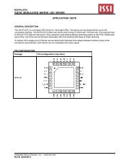
FxLED Driver For Today's Appliances
FxLED Driver For Today's Appliances
FxLED Driver For Today's Appliances
- No tags were found...

Create successful ePaper yourself
Turn your PDF publications into a flip-book with our unique Google optimized e-Paper software.
August 2013 • 1623 Buckeye Dr.Milpitas, CA. 95035 • Tel: 408.969.6600 • Support: analog@issi.com • www.issi.com<br />
1
PWM Data<br />
In this article, we will explore how to use ISSI’s<br />
<strong>FxLED</strong> TM drivers to open up a new dimension in<br />
visibility by using specific colors to make the User<br />
Interface (UI) look sleek and informative.<br />
<strong>For</strong> this application example, an air conditioning<br />
appliance was designed with sensors that detect<br />
a room’s ambient air quality. The IS31FL3218 was<br />
selected to drive a dual colored linear display of 18<br />
Red and 18 Green LEDs to graphically display the<br />
sensed air quality.<br />
The IS31FL3218 is the optimum LED driver since it<br />
is comprised of 18 constant current channels each<br />
with independent PWM control. The average output<br />
current of each channel can be adjusted in 256<br />
steps by changing the PWM duty cycle through an<br />
I2C interface. This fine level of LED dimming control<br />
is optimum for creating smooth color light transition<br />
effects such as a gradual modulation of LED brightness<br />
at turn ON and turn OFF resulting in an “LED<br />
Breathing” effect.<br />
Gamma Correction<br />
In order to perform a better visual LED breathing<br />
effect ISSI recommends using a gamma corrected<br />
PWM value to set the LED intensity. Gamma correction,<br />
also known as gamma compression or encoding,<br />
is used to encode linear luminance to match the<br />
non-linear characteristics of an LED display. Since<br />
the IS31FL3218 can modulate the brightness of the<br />
LEDs with 256 steps, a gamma correction function<br />
can be applied when computing each subsequent<br />
LED intensity step resulting in changes in brightness<br />
that match the human eye’s brightness curve. This<br />
results in a reduced number of steps for the LED<br />
intensity setting, yet still appears linear to the<br />
human eye.<br />
Choosing more gamma steps results in a more<br />
continuous and smooth-looking breathing effect,<br />
especially when creating very long breathing cycles.<br />
The recommended number of gamma steps is defined<br />
by the breath cycle T. When T=1s, choose 32<br />
gamma steps, when T=2s, choose 64 gamma steps.<br />
The user must decide the final number of gamma<br />
steps required to generate the preferred visual effect<br />
on the LED display which can vary with differences<br />
in LED characteristics. (See the gamma step<br />
comparison below).<br />
Table 1-32 Gamma steps with 256 PWM step<br />
C(0) C(1) C(2) C(3) C(4) C(5) C(6) C(7)<br />
0 1 2 4 6 10 13 18<br />
C(8) C(9) C(10) C(11) C(12) C(13) C(14) C(15)<br />
22 28 33 39 46 53 61 69<br />
C(16) C(17) C(18) C(19) C(20) C(21) C(22) C(23)<br />
78 86 96 106 116 126 138 149<br />
C(24) C(25) C(26) C(27) C(28) C(29) C(30) C(31)<br />
161 173 186 199 212 226 240 255<br />
Fig 1 - Gamma Correction (32 steps)<br />
256<br />
224<br />
192<br />
160<br />
128<br />
96<br />
64<br />
32<br />
0<br />
0<br />
4 8 12 16 20 24 28 32<br />
Intensity Steps<br />
August 2013 • 1623 Buckeye Dr.Milpitas, CA. 95035 • Tel: 408.969.6600 • Support: analog@issi.com • www.issi.com<br />
2
PWM Data<br />
Fig 2 - Gamma Correction (64 steps)<br />
256<br />
224<br />
192<br />
160<br />
128<br />
96<br />
64<br />
32<br />
0<br />
0<br />
8 16 24 32 40 48 56 64<br />
Intensity Steps<br />
In this application, each of the IS31FL3218 output<br />
channels was configured to drive two LEDs of the<br />
same color, Red or Green. This resulted in nine<br />
channels for Red and the other nine channels for<br />
Green; altogether 36 LEDs were used.<br />
Table 2-64 Gamma steps with 256 PWM step<br />
C(0) C(1) C(2) C(3) C(4) C(5) C(6) C(7)<br />
0 1 2 3 4 5 6 7<br />
C(8) C(9) C(10) C(11) C(12) C(13) C(14) C(15)<br />
8 10 12 14 16 18 20 22<br />
C(16) C(17) C(18) C(19) C(20) C(21) C(22) C(23)<br />
24 26 29 32 35 38 41 44<br />
C(24) C(25) C(26) C(27) C(28) C(29) C(30) C(31)<br />
47 50 53 57 61 65 69 73<br />
C(32) C(33) C(34) C(35) C(36) C(37) C(38) C(39)<br />
77 81 85 89 94 99 104 109<br />
C(40) C(41) C(42) C(43) C(44) C(45) C(46) C(47)<br />
114 119 124 129 134 140 146 152<br />
C(48) C(49) C(50) C(51) C(52) C(53) C(54) C(55)<br />
158 164 170 176 182 188 195 202<br />
C(56) C(57) C(58) C(59) C(60) C(61) C(62) C(63)<br />
209 216 223 230 237 244 251 255<br />
Fig 3 - IS31FL3218 schematic for driving Red and Green LEDs<br />
SDA<br />
SCL<br />
SDB<br />
+5V<br />
R71<br />
4.7K<br />
R72<br />
4.7K<br />
R73<br />
100K<br />
J04<br />
OR<br />
C20<br />
104P<br />
R74<br />
3.3K<br />
3<br />
5<br />
6<br />
24<br />
2<br />
4<br />
VCC<br />
IS31FL3218<br />
SDA<br />
SCL<br />
SDB<br />
R_EXT<br />
GND<br />
OUT1<br />
OUT2<br />
OUT3<br />
OUT4<br />
OUT5<br />
OUT6<br />
OUT7<br />
OUT8<br />
OUT9<br />
OUT10<br />
OUT11<br />
OUT12<br />
OUT13<br />
OUT14<br />
OUT15<br />
OUT16<br />
OUT17<br />
OUT18<br />
7<br />
8<br />
9<br />
10<br />
11<br />
12<br />
13<br />
14<br />
15<br />
16<br />
17<br />
18<br />
19<br />
20<br />
21<br />
22<br />
23<br />
1<br />
SEG2<br />
SEG3<br />
SEG4<br />
SEG5<br />
SEG6<br />
SEG18<br />
SEG9<br />
SEG8<br />
SEG7<br />
SEG10<br />
SEG11<br />
SEG12<br />
SEG13<br />
SEG14<br />
SEG15<br />
SEG16<br />
SEG17<br />
SEG1<br />
+5V-2<br />
SEG1<br />
SEG2<br />
SEG3<br />
SEG4<br />
SEG5<br />
SEG6<br />
SEG7<br />
SEG8<br />
SEG9<br />
SEG10<br />
SEG11<br />
SEG12<br />
SEG13<br />
SEG14<br />
SEG15<br />
SEG16<br />
SEG17<br />
SEG18<br />
1<br />
2<br />
3<br />
4<br />
5<br />
6<br />
7<br />
8<br />
9<br />
10<br />
11<br />
12<br />
13<br />
14<br />
15<br />
16<br />
17<br />
18<br />
19<br />
COM1<br />
SEG1<br />
SEG2<br />
SEG3<br />
SEG4<br />
SEG5<br />
SEG6<br />
SEG7<br />
SEG8<br />
SEG9<br />
SEG10<br />
SEG11<br />
SEG12<br />
SEG13<br />
SEG14<br />
SEG15<br />
SEG16<br />
SEG17<br />
SEG18<br />
LED Connector<br />
August 2013 • 1623 Buckeye Dr.Milpitas, CA. 95035 • Tel: 408.969.6600 • Support: analog@issi.com • www.issi.com<br />
3
Fig 4 - Schematic of LED arrangement, Red and Green LEDs are paired<br />
Fig 5 - LED bar placement of Red and Green LEDs<br />
The 18 Red LEDs are put into a straight row while<br />
the other 18 Green LEDs are placed into another<br />
row beneath the Red row (Fig 5). With this arrangement<br />
it is possible to color mix the two rows of Red<br />
and Green LEDs to generate a hue of Red/Green<br />
colors. The pure Green color is used to indicate<br />
good air quality while the solid Red color indicates<br />
poor air quality. Colors obtained by mixing Red and<br />
Green, for example Yellow, would indicate a variation<br />
in levels of air quality between good and poor,<br />
see Fig. 6 below.<br />
To make the display even more fancy and attractive,<br />
animation was added to the color legend. <strong>For</strong> this<br />
application the color illumination would initialize<br />
at the center of the bar graph and expand all the<br />
way to both the left and right sides. After the entire<br />
bar graph is fully illuminated the LEDs begin to turn<br />
OFF starting from the left and right sides, collapsing<br />
towards the center. The illumination cycle is continuously<br />
repeated so as to aesthetically attract attention<br />
to the air quality status, see Fig. 7 below.<br />
Fig 6 - Color legend to indicate air quality<br />
Fig 7 - Moving visual effect<br />
Good<br />
Fair<br />
Poor<br />
August 2013 • 1623 Buckeye Dr.Milpitas, CA. 95035 • Tel: 408.969.6600 • Support: analog@issi.com • www.issi.com<br />
4
Fig. 8 shows the block diagram of the implementation.<br />
A micro-controller (MCU) is used to send commands<br />
and data to set up the internal registers of the<br />
IS31FL3218 <strong>FxLED</strong> driver. The programmed <strong>FxLED</strong><br />
driver outputs PWM signals on its output channels<br />
which drive the LED rows, this results in the desired<br />
color mixing and breath lighting effects.<br />
Fig - 8 Block Diagram<br />
Breath Effect<br />
To further implement the gradually turn-ON and<br />
turn-OFF lighting effect, simply known as ‘breathing’<br />
effect, the output is further divided into 32 or 64<br />
brightness levels, as shown in Tables 1 and 2. Note<br />
that increasing the number of brightness steps will<br />
cause the ‘breathing’ effect to appear smoother.<br />
After setting the (x,y) value to the desired color, it is<br />
next multiplied by the brightness value, n, to obtain<br />
the complete color mixing equation,<br />
(RED:GREEN)n = (xn:yn) = [(x*n/32):(y*n/32)]n<br />
MCU 12C Bus<br />
ISSI<br />
<strong>FxLED</strong><br />
IS31FL3218<br />
PWM<br />
With gamma correction:<br />
(RED:GREEN)n = (xn:yn) =<br />
[(x*C(n)/255):(y*C(n)/255)]n<br />
Where, n is an integer between 0 and 31;<br />
<strong>For</strong> gamma corrected values C(n), refer to table 1<br />
<strong>For</strong> this application, the Air Conditioner’s main MCU is<br />
used to set up the values of the IS31FL3218’s internal<br />
registers. Once the initial set up is completed, the main<br />
MCU is freed up from the necessity of performing LED<br />
control functions. It can resume its original control<br />
tasks for the air conditioner.<br />
Color Mixing<br />
Color mixing is accomplished by varying the channel<br />
to channel RED and Green LED brightness levels. To<br />
accomplish this, the 18 internal PWM registers are<br />
programmed so they output different pulse widths for<br />
each of the 18 output channels; the longer the pulse<br />
width the brighter the LED on that channel. The pulse<br />
width of each output channel is controlled by an 8-bit<br />
value stored in the <strong>FxLED</strong> PWM registers. The following<br />
equation shows how Red and Green color mixing is<br />
accomplished,<br />
RED:GREEN = (x) : (y) = [0..255] : [0..255]<br />
where, x and y are any integer values between 0 to 255.<br />
<strong>For</strong> example,<br />
when x=0, y=255, GREEN color is obtained;<br />
when x=255, y=0, RED color is obtained;<br />
when x=255, y=255, YELLOW color is obtained;<br />
when x=64, y=148, GREENISH YELLOW is obtained;<br />
The resulting numbers, xn and yn must be rounded<br />
off into an integer between 0 and 255. Please note<br />
that x and y can’t be too small or color difference<br />
will not be noticeable.<br />
<strong>For</strong> example, if the air quality is detected to be<br />
middle to good; the color to display is Greenish Yellow<br />
in which x=64 and y=148.<br />
At time = 0, the LED is off, therefore, n=0, then,<br />
(RED:GREEN)=(64*0/32:148*0/32)=(0:0)<br />
At time = 1, the LED starts to turn on at brightness<br />
level 1, n=1, then,<br />
(RED:GREEN) = (64*1/32:148*1/32) = (2:2.625) or<br />
(2: 3)<br />
At time = 8, the LED is in 25% bright, n=8, then, (RED<br />
:GREEN)=(64*8/32:148*8/32)=(16:37).<br />
By sending different values to each individual PWM<br />
register, different color mix and brightness can be<br />
achieved. The IS31FL3218 guarantees the output current<br />
of each LED channel is precisely matched so the<br />
color of each LED will be perfectly uniform on the bar<br />
graph. The result is an aesthetically pleasing and informative<br />
display worthy of today’s sleek appliances.<br />
August 2013 • 1623 Buckeye Dr.Milpitas, CA. 95035 • Tel: 408.969.6600 • Support: analog@issi.com • www.issi.com<br />
5
ISSI <strong>FxLED</strong> Product Line<br />
The <strong>FxLED</strong> family of Matrix, Multichannel and RGB<br />
LED drivers provides system designers with a wide<br />
range of options for bringing eye-catching color<br />
functionality to consumer electronics. <strong>For</strong> example,<br />
the Matrix line of LED drivers can be used to build<br />
an LED graphic panel for message boards and animated<br />
graphic displays; the Multichannel drivers can<br />
be used with light guides for informative appliance<br />
displays and the RGB drivers are perfect for low-cost<br />
color lighting. Overall, ISSI’s broad portfolio of <strong>FxLED</strong><br />
drivers simplifies the blending of Red-Green-Blue<br />
LEDs to produce a broad range of predefined colors<br />
and lighting sequences for driving 3 to 144 LEDs.<br />
<strong>For</strong> more information, please visit our website at<br />
http://www.issi.com/US/product-analog-fxled-driv<br />
er.shtml or send your enquiry to analog@issi.com<br />
August 2013 • 1623 Buckeye Dr.Milpitas, CA. 95035 • Tel: 408.969.6600 • Support: analog@issi.com • www.issi.com<br />
6