IS31LT3910 T8 Evaluation Board Guide - Integrated Silicon Solution ...
IS31LT3910 T8 Evaluation Board Guide - Integrated Silicon Solution ...
IS31LT3910 T8 Evaluation Board Guide - Integrated Silicon Solution ...

Create successful ePaper yourself
Turn your PDF publications into a flip-book with our unique Google optimized e-Paper software.
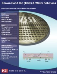
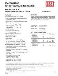
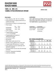
<strong>IS31LT3910</strong> <strong>T8</strong> <strong>Evaluation</strong> <strong>Board</strong> <strong>Guide</strong>DescriptionThe <strong>IS31LT3910</strong> is a peak current mode control LEDdriver IC. The <strong>IS31LT3910</strong> operates in constantoff-time mode. It allows efficient operation of HighBrightness (HB) LEDs with voltage sources rangingfrom 8VDC to 450VDC or 110VAC/220VAC. The<strong>IS31LT3910</strong> includes a PWM dimming input that canaccept an external control signal with a duty ratio of 0 -100% and a frequency of up to a few kilohertz. It alsoincludes a 50 - 240mV linear dimming input which canbe used either for linear dimming or for temperaturecompensation of the LED current. The <strong>IS31LT3910</strong> isideally suited for buck LED drivers. Since the<strong>IS31LT3910</strong> operates in peak current mode control, thecontroller achieves good output current regulationwithout the need for any loop compensation. Itachieves good PWM dimming response because theresponse time is limited only by the rate of rise and fallof the inductor current, enabling very fast rise and falltime.Features• Wide input range from 8VDC to 450VDC or110VAC/220 VAC• Temperature compensation to regulate LED current• Application from a few mA to more than 1A output• Constant off-time operation• Linear and PWM dimming capability• Requires few external components for operationApplications• DC/DC or AC/DC LED driver applications• General purpose constant current source• Signal and decorative LED lighting• Backlighting LED driverQuick StartRecommended Equipment• 90~240VAC/50~60Hz power supply• LEDs (12 in series and 24 in parallel)• MultimeterAbsolute Maximum Ratings• ≤ 265VAC power supply• ≤ 42V Vout (Total Vf)Caution: Do not exceed the conditions listed above,otherwise the board will be damaged or the outputwill be limited.ProcedureThe <strong>IS31LT3910</strong> <strong>Evaluation</strong> <strong>Board</strong> is fully assembledand tested. Follow the steps listed below to verify boardoperation.Caution: Do not turn on the power supply until allconnections are completed.AC1AC2<strong>IS31LT3910</strong><strong>Board</strong>LED+LED-LEDArray1) Connect the positive terminal of the LEDs to theLED+ pin of the DEMO and the negative terminalof the LEDs to the LED- pin of the DEMO.2) Connect the input pins (L and N) of the DEMO toAC power supply.3) Turn on the power supply.Ordering InformationPART #<strong>IS31LT3910</strong>_<strong>T8</strong>_EBTEMPRANGE-40 °C to85°CIC PACKAGESOP-8(5.0 x 6.0mm)For pricing, delivery, and ordering information, please contact ISSI at analog_mkt@issi.com or call+1-408-969-6600<strong>Integrated</strong> <strong>Silicon</strong> <strong>Solution</strong>, Inc. – www.issi.comR1.0, 08/26/20111
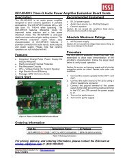
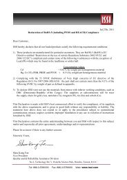
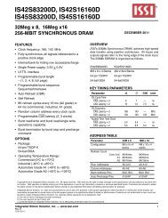
<strong>IS31LT3910</strong> <strong>T8</strong> <strong>Evaluation</strong> <strong>Board</strong> <strong>Guide</strong><strong>IS31LT3910</strong>Figure 1. <strong>IS31LT3910</strong> <strong>Evaluation</strong> <strong>Board</strong> SchematicFigure 2. Picture of <strong>Evaluation</strong> <strong>Board</strong>NOTE: Physical dimensions are (L x W x H): 28.1mm x 17mm x 12mmFigure 3. PCB Layout- Top LayerFigure 4. PCB Layout- Bottom LayerLine Regulation Rate and EfficiencyInput Voltage Input Power PF Output Voltage Output Current EfficiencyAC:90V 18.45W 0.851 38.42V 0.416A 86.63%AC:110V 18.39W 0.886 38.42V 0.420A 87.75%AC:130V 18.31W 0.873 38.39V 0.420A 88.06%AC:180V 18.37W 0.826 38.37V 0.422A 88.14%AC:220V 18.57W 0.809 38.35V 0.422A 87.15%AC:240V 18.68W 0.801 38.32V 0.422A 86.57%<strong>Integrated</strong> <strong>Silicon</strong> <strong>Solution</strong>, Inc. – www.issi.comR1.0, 08/26/20112
<strong>IS31LT3910</strong> <strong>T8</strong> <strong>Evaluation</strong> <strong>Board</strong> <strong>Guide</strong>Bill of MaterialsNo. Name Description Ref Des. Qty. MFR P/N1 X Capacitor 0.1uF,275V C1, C1.1 22 Film Capacitor 10nF,630V C2 13 AL Capacitor 33uF,100V C7 14 AL Capacitor 22uF,250V C3, C4 25 SMD Capacitor 10uF,25V,0805,X7R C5 16 SMD Capacitor 1uF,25V,0805,X7R C8 17 SMD Capacitor 390pF,25V,0805,X7R C6 18 Inductor 3mH,10%,8*10,Isat>100mA L3, L3.1 29 EE Inductor 0.65mH,Isat≥800mA L5, L6 210 SMD Inductor 10 uH,Isat≥800mA L4 111 Zener Diode 6.5V,5% DZ1 112 Zener Diode 39V,5% DZ2 113 FR Diode 1A,600V,ESIJ,SMA D8, D9 114 FR Diode 1N4148 D10 115 Opto-coupler P521GB IC2 116 N-MOSFET 4N60,4A,600V,TO-220 Q1 117 Fuse 1A,250V,3*10 Fuse 118 IC <strong>IS31LT3910</strong>,SOP-8 IC1 119 Resistor 4.7Ω,1W,1% R11 120 Resistor 4.7Ω,1W,1% R12 121 Resistor 220KΩ,1W,1% R4, R5 222 Resistor 150KΩ,0805,1% R6 123 Resistor 4.7KΩ,0805,1% R1, R2 224 Resistor 0.47Ω,0805,1% R9, R10 225 Resistor 10Ω,0805,1% R7 226 Resistor 33Ω,0805,1% R8 227 Resistor 100Ω,0805,1% R16 228 Resistor 1KΩ,0805,1% R15 229 Resistor 30K,0805,1% R13 1<strong>Integrated</strong> <strong>Silicon</strong> <strong>Solution</strong>, Inc. – www.issi.comR1.0, 08/26/20113
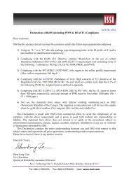
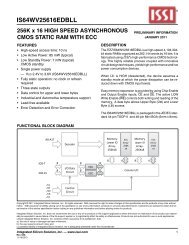
<strong>IS31LT3910</strong> <strong>T8</strong> <strong>Evaluation</strong> <strong>Board</strong> <strong>Guide</strong>EMI test<strong>Integrated</strong> <strong>Silicon</strong> <strong>Solution</strong>, Inc. – www.issi.comR1.0, 08/26/20114
<strong>IS31LT3910</strong> <strong>T8</strong> <strong>Evaluation</strong> <strong>Board</strong> <strong>Guide</strong>Copyright © 2011 <strong>Integrated</strong> <strong>Silicon</strong> <strong>Solution</strong>, Inc. All rights reserved. ISSI reserves the right to make changes to this specification and its products at any timewithout notice. ISSI assumes no liability arising out of the application or use of any information, products or services described herein. Customers are advisedto obtain the latest version of this device specification before relying on any published information and before placing orders for products.<strong>Integrated</strong> <strong>Silicon</strong> <strong>Solution</strong>, Inc. does not recommend the use of any of its products in life support applications where the failure or malfunction of theproduct can reasonably be expected to cause failure of the life support system or to significantly affect its safety or effectiveness. Products are not authorizedfor use in such applications unless <strong>Integrated</strong> <strong>Silicon</strong> <strong>Solution</strong>, Inc. receives written assurance to its satisfaction, that:a.) the risk of injury or damage has been minimized;b.) the user assume all such risks; andc.) potential liability of <strong>Integrated</strong> <strong>Silicon</strong> <strong>Solution</strong>, Inc is adequately protected under the circumstance<strong>Integrated</strong> <strong>Silicon</strong> <strong>Solution</strong>, Inc. – www.issi.comR1.0, 08/26/20115