Dahon Eco 3 Folding Bike Shifters Manual
Dahon Eco 3 Folding Bike Shifters Manual
Dahon Eco 3 Folding Bike Shifters Manual

You also want an ePaper? Increase the reach of your titles
YUMPU automatically turns print PDFs into web optimized ePapers that Google loves.
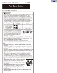
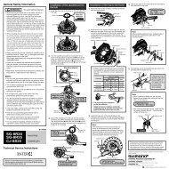
General Safety Information<br />
WARNING<br />
• Use neutral detergent to clean the chain. Do not use alkali-based or acid based detergent such as rust cleaners as it may<br />
result in damage and/or failure of the chain.<br />
• Use the reinforced connecting pin only for connecting the narrow type of chain.<br />
• There are two different types of reinforced connecting pins available. Be sure to check the table below before selecting<br />
which pin to use. If connecting pins other than reinforced connecting pins are used, or if a reinforced connecting pin or tool<br />
which is not suitable for the type of chain is used, sufficient connection force may not be obtained, which could cause the<br />
chain to break or fall off.<br />
Chain<br />
9-speed super narrow<br />
chain such as<br />
CN-7701 / CN-HG93<br />
8- / 7- / 6-speed narrow<br />
chain such as<br />
CN-HG50 / CN-IG51<br />
Reinforced connecting pin<br />
6.5mm<br />
7.1mm<br />
Silver<br />
Black<br />
Chain tool<br />
TL-CN32 / TL-CN23<br />
TL-CN32 / TL-CN23<br />
• If it is necessary to adjust the length of the chain due to a change in the number of sprocket<br />
Reinforced Connecting Pin<br />
teeth, make the cut at some other place than the place where the chain has been joined<br />
using a reinforced connecting pin or an end pin. The chain will be damaged if it is cut at a<br />
place where it has been joined with a reinforced connecting pin or an end pin.<br />
• Check that the tension of the chain is correct and that the chain is not damaged. If the<br />
tension is too weak or the chain is damaged, the chain should be replaced. If this is not<br />
done, the chain may break and cause serious injury.<br />
End Pin<br />
Link Pin<br />
• Check that the wheels are fastened securely before riding the bicycle. If the wheels are loose in any way, they may come off<br />
the bicycle and serious injury may result.<br />
• Obtain and read the service instructions carefully prior to installing the parts. Loose, worn, or damaged parts may cause<br />
injury to the rider.<br />
We strongly recommend only using genuine Shimano replacement parts.<br />
• Read these Technical Service Instructions carefully, and keep them in a safe place for later reference.<br />
Note<br />
• The reinforced connecting pins cannot be used with the UG chain, otherwise the connections will not move properly and<br />
noise will occur.<br />
• If gear shifting operations do not feel smooth, wash the derailleur and lubricate all moving parts.<br />
• If the amount of looseness in the links is so great that adjustment is not possible, you should replace the derailleur.<br />
• You should periodically clean the derailleur and lubricate all moving parts (mechanism and pulleys).<br />
• If gear shifting adjustment cannot be carried out, check the degree of parallelism at the rear end of the bicycle. Also check if<br />
the cable is lubricated and if the outer casing is too long or too short.<br />
• If you hear abnormal noise as a result of looseness in a pulley, you should replace the pulley.<br />
• If the wheel becomes stiff and difficult to turn, you should lubricate it with grease.<br />
• Do not apply any oil to the inside of the hub, otherwise the grease will come out.<br />
• You should periodically wash the sprockets in a neutral detergent and then lubricate them again. In addition, cleaning the<br />
chain with neutral detergent and lubricating it can be a effective way of extending the useful life of the sprockets and the<br />
chain.<br />
• If the chain keeps coming off the sprockets during use, replace the sprockets and the chain.<br />
• Use an outer casing which still has some length to spare even when the handlebars are turned all the way to both sides.<br />
Furthermore, check that the shifting lever does not touch the bicycle frame when the handlebars are turned all the way.<br />
• Grease the inner cable and the inside of the outer casing before use to ensure that they slide properly.<br />
• Use a frame with internal cable routing is strongly discouraged as it has tendencies to impair the SIS shifting function due to<br />
its high cable resistance.<br />
• Operation of the levers related to gear shifting should be made only when the front chainwheel is turning.<br />
• For smooth operation, use the specified outer casing and bottom bracket cable guide.<br />
• To ensure the best performance, be sure to use only the specified type of chain. The wide type chain cannot be used.<br />
• For maximum performance we highly recommend Shimano lubricants and maintenance products.<br />
• Parts are not guaranteed against natural wear or deterioration resulting from normal use.<br />
• For any questions regarding methods of installation, adjustment, maintenance or operation, please contact a professional<br />
bicycle dealer.<br />
Specifications<br />
Shifting lever<br />
Model number<br />
Gears<br />
Rear derailleur<br />
Model number<br />
Gears<br />
Tooth combination<br />
Mounting the shifting lever<br />
Install the brake lever in a position where it will not obstruct brake<br />
operation.<br />
Do not use in a combination which causes brake operation to be<br />
obstructed.<br />
Handlebar<br />
SL-RS43-7<br />
SIS 7 - gears<br />
7<br />
14, 16, 18, 20, 22, 24, 34T<br />
14, 16, 18, 20, 22, 24, 28T<br />
13, 15, 17, 19, 21, 24, 34T<br />
Half grip<br />
Tightening torque:<br />
2 N·m {18 in. lbs.}<br />
SL-RS43-6<br />
SIS 6 - gears<br />
Type<br />
Gears<br />
Total capacity<br />
Rear largest sprocket<br />
Rear smallest sprocket<br />
Smartcage<br />
7 / 6<br />
43T<br />
28-34T<br />
11T<br />
Smartcage<br />
7 / 6<br />
43T<br />
28-34T<br />
11T<br />
Smartcage<br />
7 / 6<br />
43T<br />
28-34T<br />
11T<br />
GS<br />
6<br />
34T<br />
28T<br />
14T<br />
SS<br />
6<br />
28T<br />
28T<br />
14T<br />
SS<br />
7 / 6<br />
17T<br />
28T<br />
11T<br />
Front chainwheel tooth difference 20T<br />
20T<br />
20T 20T 13T ––<br />
Sprocket tooth configurations<br />
3 mm Allen Key<br />
RD-TX70<br />
RD-TX50<br />
Leave a gap of 0.5 mm between the Revo-shift<br />
lever and the half grip.<br />
RD-TX30<br />
6<br />
RD-TY18<br />
14, 16, 18, 21, 24, 34T<br />
14, 16, 18, 21, 24, 28T<br />
Gear shifting operation<br />
Pedaling becomes<br />
heavier<br />
RD-FT30<br />
Pedaling becomes<br />
lighter<br />
Cable securing and stroke adjustment<br />
< RD-TX70 / RD-TX50 / RD-FT30 ><br />
Place the outer casing so that it does not touch the basket and<br />
mudguard, otherwise it may cause a problem with the performance of<br />
the derailleur.<br />
Set the outer casing (RD-TX70/RD-TX50/RD-FT30) so that its<br />
length is as follows.<br />
• If routing the casing upward:<br />
(The chain should be on the largest chainring and on<br />
the largest sprocket.)<br />
Add 10 mm to the length of the outer casing from the<br />
end that is inserted into the outer casing holder to the<br />
end which is inserted into the link.<br />
Chain position<br />
Largest<br />
sprocket<br />
• If routing the casing downward:<br />
(The chain should be on the largest chainring and on the largest<br />
sprocket.)<br />
Set the length of the outer casing so that it describes a smooth arc,<br />
and so that the link stops in a position where there is a small gap<br />
between the link and the link stop.<br />
Largest<br />
sprocket<br />
1. Top adjustment<br />
Largest<br />
chainring<br />
Chain position<br />
Largest<br />
chainring<br />
Link<br />
Link stop<br />
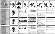
Connect the inner cable to the<br />
derailleur as shown in the illustration.<br />
Turn the top adjustment screw to adjust so that the guide pulley is<br />
below the outer line of the smallest sprocket when looking from the<br />
rear.<br />
Outer line of smallest<br />
sprocket<br />
Link<br />
max.<br />
angle<br />
max.<br />
angle<br />
Inner cable<br />
L<br />
RD-TY18<br />
Outer casing<br />
holder<br />
3. Low adjustment<br />
Turn the low adjustment screw so that the guide pulley moves to a<br />
position directly below the largest sprocket.<br />
Largest<br />
sprocket<br />
Guide pulley<br />
2<br />
SIS Adjustment<br />
Operate the shifting lever several times to move<br />
the chain to the 2nd sprocket. Then, while<br />
pressing the lever just enough to take up the play<br />
in the lever, turn the crank arm.<br />
When shifting to 3rd<br />
adjustment<br />
ballel<br />
1<br />
RD-TX70/50<br />
RD-FT30<br />
RD-TX30<br />
1 2<br />
RD-TX70 / TX50 / TX30<br />
Tighten the outer cable adjusting<br />
barrel until the chain returns to<br />
the 2nd sprocket. (clockwise)<br />
Low adjustment<br />
screw<br />
RD-TY18<br />
When no sound at<br />
all is heard<br />
adjustment<br />
ballel<br />
RD-FT30<br />
4. How to use the B-tension adjustment screw<br />
< RD-TX70 / RD-TX50 / RD-TX30 ><br />
Mount the chain on the smallest chainring and the largest sprocket,<br />
and turn the crank arm<br />
backward. Then turn the B-<br />
Largest sprocket Smallest sprocket<br />
tension adjustment screw to<br />
2<br />
2<br />
adjust the guide pulley as close<br />
to the sprocket as possible but<br />
not so close that it touches.<br />
Next, set the chain to the<br />
smallest sprocket and repeat the<br />
above to make sure that the<br />
1 2<br />
pulley does not touch the<br />
sprocket.<br />
1<br />
1 B-tension<br />
adjustment screw<br />
RD-TX70/50<br />
RD-FT30<br />
Play<br />
RD-TX30<br />
Loosen the outer casing<br />
adjustment barrel until the chain<br />
touches the 3rd sprocket and<br />
makes noise. (counter clockwise)<br />
Technical Service Instructions<br />
Rear Drive System<br />
SI-6KP0A<br />
Installation of the rear derailleur<br />
Direct-mount type<br />
Tightening torque:<br />
8 - 10 N·m<br />
{70 - 86 in. lbs.}<br />
Push in and tighten<br />
Installation of the freewheel<br />
5 mm Allen Key<br />
Bracket type<br />
Tightening torque:<br />
3 - 4 N·m<br />
{26 - 34 in. lbs.}<br />
Frame<br />
Bracket bolt<br />
Bracket<br />
Bracket nut<br />
Guide pulley<br />
1 2<br />
1 2<br />
RD-TX70 / TX50 / TX30<br />
Top<br />
adjustment<br />
screw<br />
RD-FT30<br />
2. Connection and securing of cable<br />
Connect the cable to the rear derailleur and, after taking up the initial<br />
slack in the cable, reattach to the rear derailleur as shown in the<br />
illustration.<br />
Secure the cable by pulling it with pliers with a force of 5 - 10 kg.<br />
Best setting<br />
The best setting is when the shifting lever is operated<br />
just enough to take up the play and the chain touches<br />
the 3rd sprocket and makes noise.<br />
* Return the lever to its original position (the position<br />
where the lever is at the 2nd sprocket setting and it has<br />
been released) and then turn the crank arm clockwise.<br />
If the chain is touching the 3rd sprocket and making<br />
noise, turn the outer casing adjustment barrel<br />
clockwise slightly to tighten it until the noise stops and<br />
the chain runs smoothly.<br />
Operate lever to change gears, and check that no<br />
noise occurs in any of the gear positions.<br />
For the best SIS performance, periodically lubricate all power-transmission<br />
parts.<br />
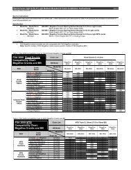
In order to realize the best performance, we recommend that the following combination be used.<br />
Series<br />
Gears<br />
Shifting lever<br />
Outer casing<br />
Rear derailleur<br />
Right<br />
Multiple freewheel<br />
Chain<br />
Bottom bracket cable guide<br />
This service instruction explains how to use<br />
and maintain the Shimano bicycle parts<br />
which have been used on your new bicycle.<br />
For any questions regarding your bicycle or<br />
other matters which are not related to<br />
Shimano parts, please contact the place of<br />
purchase or the bicycle manufacturer.<br />
7 - gears<br />
SL-RS43-7<br />
SIS40<br />
RD-TX70/RD-TX50<br />
RD-TX30<br />
MF-TZ37/HG50<br />
MF-HG37/TZ07<br />
CN-HG50<br />
SM-SP18/BT18<br />
6 - gears<br />
MF-HG40-6/HG22<br />
MF-TZ06<br />
CN-HG50<br />
SM-SP18/BT18<br />
7 - gears<br />
SIS40<br />
MF-TZ37/TZ07<br />
MF-HG50<br />
CN-HG50<br />
SM-SP18/BT18<br />
6 - gears<br />
SL-RS43-6 SL-RS43-7 SL-RS43-6<br />
SIS40<br />
RD-TX70/RD-TX50<br />
RD-TX30/RD-TY18<br />
Tourney<br />
One Holland, Irvine, California 92618, U.S.A. Phone: +1-949-951-5003<br />
RD-TX70/RD-TX50<br />
RD-TX30<br />
RD-FT30<br />
Industrieweg 24, 8071 CT Nunspeet, The Netherlands Phone: +31-341-272222<br />
Please note: specifications are subject to change for improvement without notice. (English)<br />
© Apr. 2005 by Shimano Inc. XBC SZK Printed in Singapore<br />
SIS40<br />
RD-TX70/RD-TX50<br />
RD-TX30/RD-TY18<br />
RD-FT30<br />
MF-HG40-6/HG22<br />
MF-TZ06<br />
CN-HG50<br />
SM-SP18/BT18<br />
3-77 Oimatsu-cho, Sakai, Osaka 590-8577, Japan<br />
Chain length<br />
To install<br />
To disassemble<br />
< GS > Largest<br />
Largest < SS > Smallest<br />
chainring<br />
chainring<br />
sprocket<br />
Add 2 links (with the chain on<br />
both the largest sprocket and<br />
the largest chainring)<br />
Chain<br />
Freewheel removal tool<br />
TL-FW30<br />
Tightening torque:<br />
30 N·m {260 in. lbs.}<br />
Largest<br />
chainring<br />
Chain<br />
Guide pulley<br />
Tension pulley<br />
Right angle to the ground<br />
Tightening torque:<br />
5 - 7 N·m {44 - 60 in. lbs.}<br />
Pull<br />
Note: Be sure that the cable is<br />
securely in the groove.<br />
Groove<br />
Inserting the inner cable<br />
Insert the inner cable into the outer casing from the end with the<br />
marking on it. Apply grease from the end with the marking in<br />
order to maintain cable operating<br />
efficiency.<br />
Marking<br />
Cutting the outer casing<br />
When cutting the outer casing, cut the opposite<br />
end to the end with the marking. After cutting the<br />
outer casing, make the end round so that the<br />
inside of the hole has a uniform diameter.<br />
Attach the same outer end<br />
cap to the cut end of the outer<br />
Outer end cap<br />
casing.<br />
Replacing the inner cable<br />
Replace the inner cable by carrying out<br />
steps ➀ to ➂ as shown in the illustrations.<br />
➀<br />
➁<br />
➂
E - 30<br />
SG<br />
E - 40<br />
SG<br />
o n l y<br />
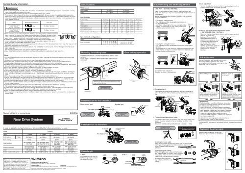
General Safety Information<br />
• Use neutral detergent to clean the chain. Do not use alkali-based or acid based detergent such as rust cleaners as it may<br />
result in damage and/or failure of the chain.<br />
• Use the reinforced connecting pin only for connecting the narrow type of chain.<br />
• There are two different types of reinforced connecting pins available. Be sure to check the table below before selecting<br />
which pin to use. If connecting pins other than reinforced connecting pins are used, or if a reinforced connecting pin or tool<br />
which is not suitable for the type of chain is used, sufficient connection force may not be obtained, which could cause the<br />
chain to break or fall off.<br />
• If it is necessary to adjust the length of the chain due to a change in the number of sprocket<br />
Reinforced Connecting Pin<br />
teeth, make the cut at some other place than the place where the chain has been joined<br />
using a reinforced connecting pin or an end pin. The chain will be damaged if it is cut at a<br />
place where it has been joined with a reinforced connecting pin or an end pin.<br />
• Be careful not to let the cuffs of your clothes get caught in the chain while riding, otherwise<br />
you may fall off the bicycle.<br />
End Pin<br />
Link Pin<br />
• Check that the tension of the chain is correct and that the chain is not damaged. If the tension is too weak or the chain is<br />
damaged, the chain should be replaced. If this is not done, the chain may break and cause serious injury.<br />
• Check that there are no cracks in the crank arms before riding the bicycle. If there are any cracks, the crank arm may break<br />
and you may fall off the bicycle.<br />
• Obtain and read the service instructions carefully prior to installing the parts. Loose, worn, or damaged parts may cause<br />
injury to the rider.<br />
We strongly recommend only using genuine Shimano replacement parts.<br />
• Read these Technical Service Instructions carefully, and keep them in a safe place for later reference.<br />
Note<br />
• The reinforced connecting pins cannot be used with the UG chain, otherwise the connections will not move properly and<br />
noise will occur.<br />
• Apply grease to the thread section of the bottom bracket and to the inside thread of the adapter before installing the bottom<br />
bracket.<br />
• In addition, if pedaling performance does not feel normal, check this once more.<br />
• Check that there is no looseness in any joints or connections before riding the bicycle. (BB-FC, FC-PD)<br />
• Do not wash the bottom bracket with high-pressure jets of water.<br />
• If you feel any looseness in the bottom bracket axle, the bottom bracket should be replaced.<br />
• If gear shifting operations do not feel smooth, wash the derailleur and lubricate all moving parts.<br />
• If the amount of looseness in the links is so great that adjustment is not possible, you should replace the derailleur.<br />
• You should periodically wash the chainrings in a neutral detergent and then lubricate them again. In addition, cleaning the<br />
chain with neutral detergent and lubricating it can be a effective way of extending the useful life of the chainrings and the<br />
chain.<br />
• If the chain keeps coming off the chainrings during use, replace the chainrings and the chain.<br />
• Use an outer casing which still has some length to spare even when the handlebars are turned all the way to both sides.<br />
Furthermore, check that the shifting lever does not touch the bicycle frame when the handlebars are turned all the way.<br />
• Grease the inner cable and the inside of the outer casing before use to ensure that they slide properly.<br />
• Operation of the levers related to gear shifting should be made only when the front chainwheel is turning.<br />
• For smooth operation, use the specified outer casing and bottom bracket cable guide.<br />
• To ensure the best performance, be sure to use only the specified type of chain. The wide type chain cannot be used.<br />
• For maximum performance we highly recommend Shimano lubricants and maintenance products.<br />
• Parts are not guaranteed against natural wear or deterioration resulting from normal use.<br />
• For any questions regarding methods of installation, adjustment, maintenance or operation, please contact a professional<br />
bicycle dealer.<br />
Technical Service Instructions<br />
In order to realize the best performance, we recommend that the following combination be used.<br />
Series<br />
Gears<br />
Shifting lever<br />
Outer casing<br />
Chain<br />
9-speed super narrow<br />
chain such as<br />
CN-7701 / CN-HG93<br />
8- / 7- / 6-speed narrow<br />
chain such as<br />
CN-HG50 / CN-IG51<br />
Front derailleur<br />
WARNING<br />
Front chainwheel<br />
Left<br />
Bottom bracket<br />
Chain<br />
Bottom bracket cable guide<br />
Reinforced connecting pin<br />
6.5mm<br />
7.1mm<br />
Silver<br />
Black<br />
Front Drive System<br />
Right<br />
Left<br />
Chain tool<br />
TL-CN32 / TL-CN23<br />
TL-CN32 / TL-CN23<br />
Tourney<br />
7 - gears<br />
6 - gears<br />
3 - gears 3 - gears<br />
SL-RS43-L<br />
SL-RS43-L<br />
SIS40<br />
SIS40<br />
FD-C051/FD-TY30<br />
FD-C050/FD-TY10<br />
FC-TX70/TC-TX71/FC-TY33<br />
FC-TS38A/FC-TY40/FC-TS32<br />
BB-UN26<br />
BB-UN26<br />
CN-HG50<br />
CN-HG50<br />
SM-SP18/BT18<br />
SM-SP18/BT18<br />
SI-6KS0A<br />
Specifications<br />
Shifting lever<br />
Model number<br />
Gears<br />
Mounting the shifting lever<br />
SL-RS43-L<br />
SIS 3 - gears<br />
FD-TY30<br />
Front Derailleur<br />
Model number<br />
FD-C051/C050<br />
Chainstay angle (a ) 66°-69°<br />
63°-66°<br />
66°-69°<br />
Front derailleur installation<br />
band diameter (Normal type)<br />
S, M, L S<br />
Front derailleur installation<br />
band diameter (Top route type)<br />
S, M, L<br />
Front chainwheel<br />
Model number<br />
Front chainwheel tooth combination<br />
Crank arm length<br />
Pedal thread dimensions<br />
Bottom bracket cup thread dimensions<br />
Applicable front derailleur<br />
Bottom Bracket<br />
Type<br />
Triple<br />
* FC-TY40 : 47.5mm ––– YL117<br />
Chain line<br />
47.5mm<br />
Install the brake lever in a position where it will not obstruct brake<br />
operation.<br />
Do not use in a combination which causes brake operation to be<br />
obstructed.<br />
Half grip<br />
Handlebar<br />
3 mm Allen Key<br />
Tightening torque:<br />
2 N·m {18 in. lbs.}<br />
FD-TY10<br />
S, M<br />
S, M<br />
66°-69°<br />
FC-TX71 FC-TY33 FC-TS38A FC-TX70<br />
Chainstay angle<br />
48T-38T-28T<br />
42T-34T-24T<br />
170mm<br />
170mm<br />
BC 9/16" X 20 T.P.I. (English thread) BC 9/16" X 20 T.P.I. (English thread)<br />
BC 1.37" X 24 T.P.I. (68, 73 mm) BC 1.37" X 24 T.P.I. (68, 73 mm)<br />
FD-C051 FD-C051/TY30 FD-C051/TY30 FD-C050 FD-C050/TY10 FD-C050/TY10<br />
Spindle length<br />
122.5mm<br />
Leave a gap of 0.5 mm between the Revo-shift<br />
lever and the half grip.<br />
Installation of the bottom bracket<br />
Install using the special tool TL-UN74.<br />
First install the main body, then the adapter.<br />
Tightening torque:<br />
50 - 70 N·m {435 - 608 in. lbs.}<br />
Installation of the front chainwheel<br />
Use the cotterless crank extractor (TL-FC10) to install the<br />
front chainwheel.<br />
Shell width<br />
68mm<br />
Adapter<br />
Stamped marking<br />
D-NL<br />
FC-TY40<br />
Thread dimensions<br />
BC1.37 X 24 T.P.I.<br />
Gear shifting operation<br />
Pedaling becomes<br />
heavier<br />
Front Chainwheel<br />
Bottom Bracket<br />
S H IMANO<br />
S G<br />
S H I MA NO<br />
F o r N A R R OW<br />
Ch a i n<br />
FC-TS32<br />
Pedaling becomes<br />
lighter<br />
Installation of the front derailleur<br />
1. < FD-C051 / FD-C050 / FD-TY30 / FD-TY10 ><br />
Adjust and then install the front derailleur as shown in the illustration. Do not<br />
remove the Pro-Set alignment block at this time.<br />
Gear teeth should<br />
come within this<br />
range 1 - 3 mm<br />
Chain length<br />
< GS > < SS ><br />
Add 2 links (with the chain on both<br />
the largest sprocket and the largest<br />
chainring)<br />
Largest<br />
chainring<br />
Chain<br />
Pro-Set alignment block<br />
2. The level section of the chain guide outer plate should be<br />
directly above and parallel to the largest chainring.<br />
3. Secure using a 9 mm spanner (TY30, TY10) or a 5 mm<br />
Allen key (C051, C050).<br />
Tightening torque:<br />
5 - 7 N·m {44 - 60 in. lbs.}<br />
Adjustment<br />
Largest<br />
chainring<br />
Smallest<br />
sprocket<br />
Be sure to follow the sequence described below.<br />
1. Low adjustment<br />
< FD-C051 / FD-C050 / FD-TY30 / FD-TY10 ><br />
First remove the Pro-Set alignment block. Next,<br />
set so that the clearance between the chain guide<br />
inner plate and the chain is 0 - 0.5 mm.<br />
FD-TY30/TY10<br />
Largest<br />
sprocket<br />
Chain position<br />
Smallest<br />
chainring<br />
Pro-Set alignment block<br />
Pro-Set gauge<br />
Chainwheel<br />
(largest chainring)<br />
Chain guide<br />
Largest<br />
chainring<br />
Chain<br />
Guide pulley<br />
Tension pulley<br />
Right angle to the ground<br />
Chain guide inner<br />
plate<br />
Chain<br />
FD-C051/C050<br />
Low<br />
adjustment<br />
screw<br />
2. Connection and securing of cable<br />
While firmly pulling the cable, tighten the fixing bolt with a 9 mm spanner (TY30,<br />
TY10) or a 5 mm Allen key (C051, C050) to secure the cable.<br />
Tightening torque: 5 - 7 N·m {44 - 60 in. lbs.}<br />
Inserting the inner cable<br />
Insert the inner cable into the outer casing from the end with the marking on it.<br />
Apply grease from the end with the marking in order to maintain<br />
cable operating efficiency.<br />
Cutting the outer casing<br />
When cutting the outer casing, cut the opposite end to the<br />
end with the marking. After cutting the outer casing, make<br />
the end round so that the inside of the hole has a uniform<br />
diameter.<br />
Attach the same outer end cap to the<br />
cut end of the outer casing.<br />
3. Adjustment of cable tension<br />
Outer end cap<br />
Marking<br />
After taking up the initial slack in the cable, re-secure to the front derailleur as<br />
shown in the illustration.<br />
Normal type<br />
Top route type<br />
Cut off the excess length of inner cable and then install the inner end cap.<br />
< FD-C051 / FD-C050 ><br />
Top route type<br />
4. Top adjustment<br />
Set so that the clearance between<br />
the chain guide outer plate and the<br />
chain is 0 - 0.5 mm.<br />
Smallest<br />
sprocket<br />
Chain position<br />
Largest<br />
chainring<br />
5. Adjustment of the intermediate chainring<br />
Set the chain onto the largest sprocket, and at the front, move the chain from<br />
the largest chainring to the intermediate chainring. Adjust using the cable<br />
adjusting bolt so that the clearance between the chain guide inner plate and<br />
the chain is 0 - 0.5 mm.<br />
Largest<br />
sprocket<br />
5 mm allen key<br />
Chain position<br />
Intermediate<br />
chainring<br />
Replacing the inner cable<br />
Replace the inner cable by carrying out steps ➀<br />
to ➂ as shown in the illustrations.<br />
FD-TY30/TY10<br />
FD-C051/C050<br />
Outer casing<br />
adjustment barrel<br />
➀<br />
➁<br />
Chain guide<br />
inner plate<br />
Chain<br />
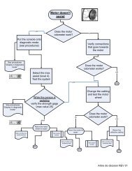
6. Troubleshooting chart<br />
After completion of steps 1 - 5, move the shifting lever to check the<br />
shifting. (This also applies if shifting becomes difficult during use.)<br />
If the chain falls to the crank side<br />
If shifting is difficult from the<br />
intermediate chainring to the largest<br />
chainring<br />
If shifting is difficult from the<br />
intermediate chainring to the<br />
smallest chainring<br />
If there is interference between the<br />
chain and the front derailleur inner<br />
plate at the largest chainring<br />
If there is interference between the<br />
chain and the front derailleur outer<br />
plate at the largest chainring<br />
If the intermediate chainring is<br />
skipped when shifting from the<br />
largest chainring<br />
If there is interference between the<br />
chain and front derailleur inner plate<br />
when the rear sprocket is shifted to<br />
the largest sprocket when the<br />
chainwheel is at the intermediate<br />
chainring position.<br />
If shifting is difficult from the largest<br />
chainring to the intermediate<br />
chainring<br />
If the chain falls to the bottom<br />
bracket side<br />
Note:<br />
Pass the cable through<br />
as shown in the<br />
illustration.<br />
Wire fixing bolt<br />
Normal type<br />
Tighten the top adjustment screw<br />
clockwise (about 1/4 turn).<br />
Loosen the top adjustment screw<br />
counterclockwise (about 1/8 turn).<br />
Loosen the low adjustment screw<br />
counterclockwise (about 1/4 turn).<br />
Tighten the top adjustment screw<br />
clockwise (about 1/8 turn).<br />
Loosen the top adjustment screw<br />
counterclockwise (about 1/8 turn).<br />
Loosen the outer casing adjustment<br />
barrel counterclockwise (1 or 2 turns).<br />
Tighten the outer casing adjustment<br />
barrel clockwise (1 or 2 turns).<br />
Tighten the low adjustment screw<br />
clockwise (about 1/2 turn).<br />
Top adjustment<br />
screw<br />
Chain guide<br />
outer plate<br />
Chain<br />
This service instruction explains how to use<br />
and maintain the Shimano bicycle parts<br />
which have been used on your new bicycle.<br />
For any questions regarding your bicycle or<br />
other matters which are not related to<br />
Shimano parts, please contact the place of<br />
purchase or the bicycle manufacturer.<br />
One Holland, Irvine, California 92618, U.S.A. Phone: +1-949-951-5003<br />
Industrieweg 24, 8071 CT Nunspeet, The Netherlands Phone: +31-341-272222<br />
Please note: specifications are subject to change for improvement without notice. (English)<br />
© Apr. 2005 by Shimano Inc. XBC SZK Printed in Singapore<br />
3-77 Oimatsu-cho, Sakai, Osaka 590-8577, Japan<br />
Tightening torque:<br />
35 - 50 N·m {305 - 435 in. lbs.}<br />
Securely tighten<br />
Pull<br />
Pull<br />
➂