E-Bike ® Service Manual 24V MODELS - V is for Voltage
E-Bike ® Service Manual 24V MODELS - V is for Voltage
E-Bike ® Service Manual 24V MODELS - V is for Voltage

You also want an ePaper? Increase the reach of your titles
YUMPU automatically turns print PDFs into web optimized ePapers that Google loves.
SERVICEMANUAL<strong>24V</strong> <strong>MODELS</strong>
E-<strong>Bike</strong> <strong>Service</strong> <strong>Manual</strong><strong>24V</strong> <strong>MODELS</strong>EV Global Motors Company10900 Wilshire BoulevardSuite 310Los Angeles, CA 90024Tel: 310/208-7076Fax: 310/208-2444www.ebike.com
Copyright © 2000 EV Global Motors CompanySecond EditionSeptember, 2000LIT-82001-00-00All rights reserved. No parts of th<strong>is</strong> publication may bereproduced or transmitted in any <strong>for</strong>m or by any meanswithout the prior perm<strong>is</strong>sion of EV Global MotorsCompany.Although every precaution has been taken to assure th<strong>is</strong>publication <strong>is</strong> complete and accurate, EV Globalassumes no liability <strong>for</strong> errors or om<strong>is</strong>sions. All in<strong>for</strong>mationcontained in th<strong>is</strong> publication <strong>is</strong> based on the latestin<strong>for</strong>mation available at the time of publication and <strong>is</strong> subjectto change without notice.
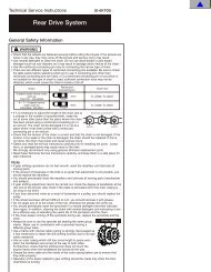
TABLE OF CONTENTSChapter One: General In<strong>for</strong>mation 1-1Beep/LED CodesTermsVehicle Identification NumberKey numberModel CodeHow to Read the Model CodeTermsLubricantsThreadlockRecommended Maintenance ScheduleSpecial ToolsChapter Two: Specifications 2-1Mechanical SpecificationsGear RatiosElectrical SpecificationsTorque SpecificationsPer<strong>for</strong>mance SpecificationsFrame SpecificationsChapter Three:Battery Pack 3-1Charging the BatteriesReplacing the BatteriesReplacing the ChargerBattery PackChapter Four: Handlebar and Controls 4-1Handlebar PositionHandlebar Height AdjustmentHandlebar ReplacementThrottle Control-HousingAccessory Control HousingHeadsetChapter Five: Brakes 5-1Brake Cable ReplacementBrake LeverBrake Lever Free Play AdjustmentBrake PadBrake Pad AlignmentCaliper ArmD<strong>is</strong>c BrakeChapter Six: Shifter and Derailleur 6-1ShifterShifter CableDerailleurChapter Seven: Chain and Crankset 7-1ChainCrank ArmChainringPedalBottom-Bracket CartridgeChapter Eight: Electrical 8-1Connector IdentificationRight Side CoverLeft Side CoverControllerQuick-Release ConnectorMotorHeadlightTaillightTroubleshootingElectrical Schematic
1-1Chapter OneGENERALINFORMATIONBEEP/LED CODESThe E-<strong>Bike</strong> beeps and flashes various codes to alert the rider to particular conditions. The followingchart l<strong>is</strong>ts the codes and describes their various functions. Beep codes cons<strong>is</strong>t of a series oflong and short beeps, like Morse code. A long beep <strong>is</strong> represented by a dash (-). A short beep <strong>is</strong> representedby a dot (•).Code Meaning Beep LEDsOK The battery pack <strong>is</strong> - - - - • -installed and properlyconnected.GO Sounds at power knob ON. - - • - - - The charge levelThe system <strong>is</strong> on andLEDs cycle twiceready to operate.Pedal ass<strong>is</strong>t The system requests • - - •pedal ass<strong>is</strong>t. Soundswhen on a steep hillor when the motor hasoverheated.Over heat 1 The motor <strong>is</strong> - - - ••••overheated.Followed by the pedalThe system will d<strong>is</strong>able the ass<strong>is</strong>t code (• - - •)motor within 3-5every 8 secondsseconds.Over heat 2 Sounds at power knob ON - - - - • -if the motor has beend<strong>is</strong>abled.in sequence.System refusal An error has been - • - - -detected. The systemwill not operate.Battery state of Indicates the battery Green = 100-60%charge state of charge within 3 Yellow = 60-20%seconds of power knob ON. Red = 20-0%Low battery The system will shut • - • •- - - Charge level LEDsdown within 3 to 5seconds.cycle continuouslyin sequence.
1-2VEHICLE IDENTIFICATION NUMBERThe 17-digit vehicle identification number(VIN) <strong>is</strong> printed on a label that <strong>is</strong> affixed tothe inside face of the right frame seat stay.Th<strong>is</strong> label also contains the gross-vehicleweight rating and recommended tire inflationpressure.KEY NUMBERThe 4-digit key number <strong>is</strong> stamped on theupper portion of the key shaft.MODEL CODEModel code Model prefix Year Description Color 1 Color 2 Color 3B1 Bicycles99-B124BV00-BK,RD 1B1 1999 Base Black (BK) Rally Red (RD) NA99-B124CV00-BK,RD 2B1 1999 Com<strong>for</strong>t Black (BK) Rally Red (RD) NA99-B124TV00-ML,CR 2B1 1999 Touring Metallic Metallic NABlue (ML) Cranberry (CR)HOW TO READ THE MODEL CODEModel Year99 B1 24 C V 00 BKProduct Line& Category Power System Model Brake Type Battery Type ColorB1 = Bicycle, 24 = 24 Volts Base = B V=V-brake 00=Lead-Acid ML=Metallic BlueConventional Com<strong>for</strong>t = C D=D<strong>is</strong>k brake CR = Metallic Cranberry RedTouring = TBK = BlackRD = Rally RedTERMSLeft and RightMost of the time, left and right in th<strong>is</strong> manualrefer to the rider’s point of view when seatedon the E-<strong>Bike</strong> and facing <strong>for</strong>ward. Theone exception to th<strong>is</strong> rule involves the brakecalipers. Left and right on the calipers refers toa technician’s point of view when standing infront of the E-<strong>Bike</strong> and looking directly at thefront brake caliper or when standing behind theE-<strong>Bike</strong> and looking directly at the rear brakecaliper.NOTE, CAUTION and WARNINGThe terms NOTE, CAUTION and WARN-ING have specific meaning in th<strong>is</strong> manual. ANOTE provides additional in<strong>for</strong>mation to makea procedure easier or clearer.A CAUTION emphasizes precautions thatmust be taken to avoid damage to your tools orto the E-<strong>Bike</strong>.A WARNING alerts you to a situation wherenegligence could lead to injury or death. TakeWARNINGS seriously. Failure to heed aWARNING could result in serious personalinjury or death.
1-3LUBRICANTSGreaseThe bearings and other mechanical componentsin the E-<strong>Bike</strong> operate at relativelylow temperatures so most automotive greasesare inappropriate <strong>for</strong> use on the E-<strong>Bike</strong>.Always use grease made specifically <strong>for</strong> abicycle, such as grease from Bullshot,Campagnolo, Fin<strong>is</strong>h Line, Pedros, Phil Wood,and Shimano.OilAlways use oils made specifically <strong>for</strong> bicycleuse. Bicycle oils need to be thin enough topenetrate tight places, they should be durableso they can withstand exposure to the elements,and they must res<strong>is</strong>t the accumulationof dirt.Suitable oils <strong>for</strong> the E-bike include Alsop,Bullshot, Campagnolo, Fin<strong>is</strong>h Line, Lube Wax,Phil Wood Tenacous Oil, Pedros, Superlube,and Triflow.Motor oil, WD40, 3-in-1 Oil, sewingmachine oil, gun oil, and other common oilsare not suitable and should not be used.In general, applying oil from a drip applicapromoteover-lubrication, which leads toexcessive accumulation of dirt. Apply oil sparingly.Apply enough oil to do the job, but not somuch that it starts to drip from the component.After applying any oil, wipe off the excess.THREADLOCKA threadlocking compound should be usedon most fasteners on the E-<strong>Bike</strong>.Threadlocking compound prevents looseningcaused by vibration and helps seal out mo<strong>is</strong>ture.Loctite 242 (blue) or equivalent <strong>is</strong> recommended<strong>for</strong> threadlocking applications. Loctite242 <strong>is</strong> a medium-strength threadlocking compoundthat permits d<strong>is</strong>assembly with commonhand tools.Be<strong>for</strong>e applying Loctite to threads, cleanthe thread surface of oil, grease, and otherresidue. Apply a small amount of Loctite.Excess compound could work its way downthe threads and bond parts together. Thetorque chart in Chapter Two includes Loctiterecommendations <strong>for</strong> particular fasteners.RECOMMENDED MAINTENANCE SCHEDULEComponent or Condition Inspect be<strong>for</strong>e every ride Inspect every 5 to 10 rides*Brake pad adjustmentXWheel quick release adjustmentXTire pressureXTire wear/damageXHead/tail/brake light operationXMirror positionXControls and d<strong>is</strong>playXSeat post quick release adjustmentXBrake pad wearXBrake cable tension/wear X XSpoke tensionXWheel trueXHub bearings adjustmentXHub bearing lubricationXChain lubricationXDerailleur adjustmentXReflectorsXBattery and chargerXHeadset adjustmentXBottom bracket adjustmentXTighten all bolts, nuts, and mountingXhardware* Depending upon length of ride and riding conditions. Inspect more frequently when riding in dusty or wetconditions.
1-4SPECIAL TOOLSThe following special tools are needed <strong>for</strong> servicing the E-<strong>Bike</strong>.ToolHex wrench set: 4mm, 5mm, 6mmHex wrench setHex wrench set: 2mm, 5mm, 3mmFourth hand cable stretcherChain checkerChain breaker (screw type)Crank wrenchCable and housing cutterGearclean brush32mm & 36mm head wrenchPedal wrenchSpoke wrench (black)Spoke wrench (red)Tire lever setFreewheel toolBottom-bracket-cartridge toolPart numberPark AWS-1Park AWS-11CPark AWS-3Park BT-2Park CC-2CPark CT-3Park CCW-14RPark CN-4CPark GSC-1Park HCW-15Park PW-3Park SW-0Park SW-2Park TL-1CPark Tool FR-1Park Tool BBT-2
2-1Chapter TwoSPECIFICATIONSTable 1: Mechanical SpecificationsComponentHeadsetStack heightDimensionsForkTypeSteerer tubeTravelStem 1Std. modelC & T modelsStem 2HandlebarStd modelR<strong>is</strong>eWidthHandleSeat postStd modelSeat post spacerSeat post, suspensionC & T modelsSeat post spacerTiresStd & C modelsT modelRimsSpokesFrontRearBottom bracket (B/B)FreewheelChainringChainring clearanceCrankarmChainSpecification33 mm (1.30 in.)25.4 mm x 34 mm x 30 mm w/sealPU Allen key adjustable1-1/8 in.65 mm17 degrees, 110 mm extension40 degrees, 110 mm extension28.6 mm x 25.4 mm x 150 mm with quill30 mm, 10 degrees620 mm200 mm300 mm x 30.0 mm O.D.100 mm x 30.1 mm ID x 34.9 mm O.D.350 mm x 27.2 mm O.D.100 mm x 27.3 I.D. x 34.9 mm O.D.26 x 1.95 in., black26 x 1.95 in., Skinwall black26 x 1.5 in., 14G x 36H, double wall266 mm, 14G stainless with brass nipples216 mm & 219 mm, 14G stainless with brass nipples127 mm cartridge14-28 T, 7-speed33 T16~17 mm (0.63~0.67 in.)170 mm (6.7 in.)1/2 x 3/32 x 110 L
2-2Chapter TwoTable 2: Gear RatiosChainring Freewheel Gear Inches Ratio33T 14T 61.3 0.42 (14/33)33T 16T 53.6 0.48 (16/33)33T 18T 47.7 0.55 (18/33)33T 20T 42.9 0.61 (20/33)33T 22T 39.0 0.67 (22/33)33T 24T 35.8 0.73 (24/33)33T 28T 30.6 0.85 (28/33)Table 3: Electrical SpecificationsComponentBattery (WP12-12)TypeCapacityChargerInputOutputCharger cordLengthWireSpecification2 in seriesDeep d<strong>is</strong>charge, sealed AGM lead-acid12 volts, 12 amp hours.115 VAC, 60/50 Hz, 2 amps24 VDC, 3 amps1.2 m (4 ft.)18 AWG, 2-wire with ground
SPECIFICATIONS 2-3Table 4: Torque SpecificationsItem kg-cm in.-lb. ft.-lb. Special InstructionsHandlebar-binder bolt 140~200 - 10~15 Apply LoctiteHandlebar-arm clamp bolts 140~200 - 10~15 Apply LoctiteStem-binder bolt (stem-2 quill bolt) 180~250 - 13~18Headset locknut 40~50 34.7~43.4Accessory control clamp bolt 30~40 26.5~34.7 -Throttle-control clamp bolt 30~40 26.5~34.7 -Controller mounting screw 15 13.0 -Brake-lever clamp bolt 30~40 26.5~34.7 -Brake-caliper pinch bolt 140~200 - 10~15 Apply LoctiteBrake-pad nut 63.6~85.2 53~71 -Caliper pivot bolt 85.2~106.8 71~89 - Apply LoctiteLeft-side-cover mounting screws 10 8.6 - Apply LoctiteRight-side-cover mounting screws 10 8.6 - Apply LoctiteBattery-terminal-block mounting screw 10 8.3 -Battery compartment mounting screw 10 8.3 -Battery pack handle 15 13.0 -Battery cover screw 20~30 17.4~26.5 Apply LoctiteCharger-board mounting screw 10 8.6 -Derailleur mounting bolt 84 70 -Derailleur pinch-mechan<strong>is</strong>m nut 42 36.5 -Shifter clamp bolt 30~40 26.5~34.7 -Mirror-mounting screw 30~40 26.5~34.7 -Chain guard screws 15 13.0 - Apply LoctiteLeft bottom-bracket cover screws 20~30 17.4~26.5 - Apply LoctiteCrank-arm mounting bolt 200~250 - 14.4~18.1 Apply grease to the boltthreadsPedal 30~50 26.5~43.4 - Apply grease to the studthreadsBottom-bracket cartridge adapter ring 300~400 - 21.7~28.9 Apply grease to the threadsChainring bolt 350~450 - 25~32 Apply oil to the bolt threadsMotor torque arm 15 13.0 - Apply LoctiteHeadlight mount 15 13.0 -Taillight mounting nut 20 17.4Horn mounting nut 15 13.0 -Cord access cover 5 4.2 -Frame mounted connector 10 8.6 - Apply LoctiteFront fender 15 13.0 -Rear fender 15 13.0 -Table 5: Per<strong>for</strong>mance Specifications*ItemTop speedRange (E mode, flat, no wind)Maximum gradeabilityAccelerationSpecification13.5-14.0 mph18-20 miles11% grade, 6 mph0-10 mph in 5.3 seconds*200-pound rider with tires inflated to 60 psi.
2-4Frame SpecificationsHead Tube163 mm (6.4 in.)Frame Size (Center to top)419 cm (16.5 in.)72˚RC 431.5 mm(17.0 in.)Wheel Base 1062.3 mm (41.8 in.)
3-1Chapter ThreeBATTERY PACKCHARGING THE BATTERIESThe E-<strong>Bike</strong> includes a charger that <strong>is</strong> anintegral part of the battery pack. Batteries canbe charged when the battery pack <strong>is</strong> on-boardthe E-bike or when the battery pack <strong>is</strong>removed <strong>for</strong> remote charging.To assure maximum battery life, alwaysfully recharge the battery after each ride. If theE-<strong>Bike</strong> will not be used <strong>for</strong> more than oneweek, remove the battery pack from the E-<strong>Bike</strong> and store it in a cool, dry place. Thecontroller uses a small amount of power wheneverthe battery pack <strong>is</strong> installed in the E-<strong>Bike</strong>. Consequently, the batteries slowly d<strong>is</strong>chargewhenever the battery pack <strong>is</strong> in place,even if the power knob <strong>is</strong> OFF. To prevent totalbattery d<strong>is</strong>charge during extended periods ofnon-use, remove the battery pack and store itin a cool, dry place. A stored battery should berecharged at least every three months to helpmaintain per<strong>for</strong>mance and quality.On-board Charging1. Be sure the power knob <strong>is</strong> turned OFF.2. Turn the battery-compartment latchesclockw<strong>is</strong>e, and open the door.3. Retrieve the charging cord from the compartmentabove the bottom bracket.4. Plug the female end of the charging cordinto the receptacle on the batterycharger.(Figure 1)FIG.1WARNINGThe charger <strong>is</strong> equipped with a cooling fan. Ifthe cooling fan does not operate when thecharging cord <strong>is</strong> plugged in and the red LED <strong>is</strong>on, unplug the charger from the electrical outletimmediately. Determine why the fan <strong>is</strong> notoperating be<strong>for</strong>e charging the battery pack.Replace the charger if necessary.5. Plug the male end of the charging cord intoa standard 110V/60 cycle electrical outlet. Thered LED on the charger and the cooling fan willautomatically turn on. The LED switches togreen and the cooling fan turns off when thebattery pack <strong>is</strong> fully charged.Remote Charging1. Remove the battery pack from the E-<strong>Bike</strong>.2. Set the battery pack on its side so the battery-packcover faces up and the handle <strong>is</strong> tothe side.
3-23. Retrieve the charging cord from the compartmentabove the bottom bracket.4. Plug the female end of the charging cordinto the receptacle on the battery charger.WARNINGThe charger <strong>is</strong> equipped with a cooling fan. Ifthe cooling fan does not operate when thecharging cord <strong>is</strong> plugged in and the red LED <strong>is</strong>on, unplug the charger from the electrical outletimmediately. Determine why the fan <strong>is</strong> notoperating be<strong>for</strong>e charging the battery pack.Replace the charger if necessary.5. Plug the male end of the charging cord intoa standard 110V/60 cycle electrical outlet. Thered LED on the charger and the cooling fan willautomatically turn on. The LED switches togreen and the cooling fan turns off when thebattery pack <strong>is</strong> fully charged.REPLACING THE BATTERIESThe battery pack contains two sealed leadacidbatteries that are connected in series. Thefollowing procedure describes how to removeand replace the two batteries.CAUTIONAlways replace both batteries as a set. Do notmix old batteries with new batteries, and do notmix different brands of batteries.WARNINGNever use a battery that <strong>is</strong> cracked or broken.Battery acid <strong>is</strong> highly corrosive and can causesevere burns if it comes in contact with youreyes or skin.Chapter Three5. Invert the battery case. Tap the case againstthe bench or floor to d<strong>is</strong>lodge the batteriesfrom the battery pack.6. Remove each battery and its damper strap(Figure 3).FIG. 2BlackBullet ConnectorBlackInterconnect Wire(Blue)Bullet ConnectorFuseRedNOTEContact your state or local agency <strong>for</strong> in<strong>for</strong>mationon proper battery d<strong>is</strong>posal.7. Properly d<strong>is</strong>pose of the old batteries.Installation1. Wrap the damper strap around the first battery(Figure 3).Removal1. Remove the battery pack from the E-<strong>Bike</strong>.2. Remove the two cover screws from the batterypack, and remove the cover.3. D<strong>is</strong>connect and remove the blue interconnectwire that connects the two batteries toeach other in series. Note the fuse on the interconnectcable (Figure 2).4. D<strong>is</strong>connect the battery-pack leads (blackand red) from the spade connectors on eachbattery.FIG.32. Set the battery into the compartment so theend with the spade connectors faces thecharger. Press the battery into the compartmentuntil it bottoms.
3-33. Repeat <strong>for</strong> the second battery.4. Inspect the fuse on the blue interconnectwire. Replace the fuse as necessary.5. Connect the blue interconnect wire to theupper battery’s positive terminal and to thelower battery’s negative terminal.6. Connect the red lead from the battery packto the positive terminal on the lower battery.7. Connect the black lead from the batterypack to the negative terminal on the upper battery.8. Fit the cover onto the battery pack. Be sureno wire <strong>is</strong> pinched beneath the cover.9. Apply Loctite 242 (blue) to the threads ofthe two cover screws, and secure the cover inplace.Installation1. Be sure the insulator (B, Figure 6) <strong>is</strong> inplace in the battery pack.2. If removed, install the spacer (A, Figure 6)onto each mounting stud in the battery pack.3. Set the charger board into place on themounting studs. Secure the board in place withthe charger-board mounting screws and washer(Figure 5).REPLACING THE CHARGERRemovalWARNINGMake sure the charger <strong>is</strong> not plugged in duringservice.1. Remove the batteries from the battery pack.2. Remove the three charger-cover screwsthat secure the cover to the vent (A, Figure 4).3. Lift the cover from the charger, and d<strong>is</strong>connectthe three electrical connectors from thecharger board.4. Remove the screw that secures the chargerboard to the bracket (B, Figure 4).FIG. 5AAABAAFIG.45. Remove the three charger-board mountingscrews (Figure 5), and remove the chargerboard. Do not lose the spacer (A, Figure 6)from each mounting stud.BAFIG. 64. Secure the board to the bracket with themounting screw (B, Figure 4).5. Plug the connectors from the cover intotheir mates in the charger board.6. Fit the cover in place over the chargerboard. Be sure the two charger wires are notpinched under the cover.7. Secure the cover in place with the threecharger-cover screws (A, Figure 4).8. Reinstall the batteries and the battery-packcover.
3-4BATTERY PACKRemoval1. Turn the power knob OFF.2. Open the battery compartment door.3. Release the gate latch, and open the batterygate.4. Use the handle to pull the battery pack fromthe compartment. Be sure to support the bottomof the battery pack with your free hand.Installation1. Set the lower end of the battery pack intothe battery compartment, and tilt the batteryinto place.NOTEThe E-<strong>Bike</strong> beeps the OK (_ _ _ _•_) wheneverthe battery pack <strong>is</strong> reinstalled and goodcontact ex<strong>is</strong>ts between the battery pack andterminal block in the E-<strong>Bike</strong>.2. Close the gate over the battery, and securethe gate latch.3. Close the battery compartment door, andturn the latches counterclockw<strong>is</strong>e.BATTERY PACK TESTCharger operation test1. Plug the female end of the charging cord intothe port on the charger.2. Plug the male end into a 110-volt outlet.3. Watch the battery charger LED and per<strong>for</strong>mthe indicated procedure.a. If the battery charger LED does not illuminate,the charger <strong>is</strong> faulty and shouldbe replaced. Unplug the charging cord,and check the battery voltage (be<strong>for</strong>echarging) as described below.b. If the battery charger LED turns tored and the cooling fan <strong>is</strong> not operating,the charger <strong>is</strong> faulty and should bereplaced. Unplug the charger, andcheck the battery voltage (be<strong>for</strong>e charging) as described below.c. If the battery charger LED turns red andthe cooling fan operates, per<strong>for</strong>m thecharger output test described below.d. If the battery charger LED turns green,per<strong>for</strong>m the charger output testdescribed below.Charger Output Test1. Remove the cover from the battery pack.2. Connect a voltmeter’s positive (+) test probeto the positive (+) battery terminal, and connectthe voltmeter’s negative (-) test probe tothe battery negative terminal as shown inFigure 7. Note the reading on the voltmeter.3. With the voltmeter still connected asdescribed in step 2, plug the charger into a110-volt outlet. Note the reading on the voltmeter.4. Compare the two readings.a. If the reading <strong>is</strong> higher when the charger<strong>is</strong> plugged in, the charger <strong>is</strong> operatingproperly. Per<strong>for</strong>m the battery voltagetest (be<strong>for</strong>e charging).b. If the two readings are the same, thecharger has failed and should bereplaced.Battery <strong>Voltage</strong> Test, Be<strong>for</strong>e Charging1. Let the battery stand <strong>for</strong> one hour.2. Remove the cover from the battery pack.3. Connect a voltmeter’s positive (+) test probeto the positive (+) battery terminal, and connectthe voltmeter’s negative (-) test probe tothe battery negative terminal as shown inFigure 7.4. Note the reading on the voltmeter.5. If the reading <strong>is</strong> less than 12 volts, the battery<strong>is</strong> faulty and should be replaced.
3-5Battery <strong>Voltage</strong> Test, After ChargingNOTEThe charger must be operational <strong>for</strong> th<strong>is</strong> test tobe valid. Per<strong>for</strong>m the charger output test be<strong>for</strong>eper<strong>for</strong>ming th<strong>is</strong> test.1. Charge the battery as described in th<strong>is</strong>chapter.2. Unplug the charger, and let the batterystand <strong>for</strong> one hour.3. Remove the cover from the battery pack.4. Connect a voltmeter’s positive (+) testprobe to the positive (+) battery terminal, andconnect the voltmeter’s negative (-) test probeto the battery negative terminal as shown inFigure 7.5. Note the reading on the voltmeter.6. The reading should be 12.5 volts or greater.If the reading <strong>is</strong> less than 12.5 volts, the battery<strong>is</strong> faulty and should be replaced.FIG. 7
4-1Chapter FourHANDLEBAR POSITIONHANDLEBARand CONTROLSNOTEThe handlebar may be adjusted to suit therider’s preference. The following proceduredescribes how to set the handlebar to the stockposition.1. Loosen the handlebar-binder bolts (A,Figure 1).HANDLEBAR HEIGHT ADJUSTMENT1. Loosen the stem-binder bolt three or fourturns counterclockw<strong>is</strong>e (A, Figure 3). If the boltr<strong>is</strong>es from the steering stem, strike the bolt witha plastic mallet to <strong>for</strong>ce the stem wedge down.AB10~20˚ACFIG. 2FIG.12. Position the handlebar so the ends pointdown slightly. The handlebar grips should <strong>for</strong>ma 10-20˚ angle with a line that parallels thefloor. See Figure 2.3. Be sure the knurled portion of the handlebar<strong>is</strong> centered within the handlebar binder.4. Tighten the handlebar-binder bolts to thetorque specification in Table 4.FIG. 3BBA
4-2CAUTIONThe "Minimum Insert" mark on the handlebarstem must not sit above the top of the headset.2. Ra<strong>is</strong>e or lower the stem within the headtube until the handlebar <strong>is</strong> at the desiredheight.3. Rotate the handlebar from side to side, andalign the handlebar with the wheel or <strong>for</strong>kdropouts.4. Tighten the stem-binder bolt to the torquespecification in Table 4.HANDLEBAR REPLACEMENTRemoval1. Note how the brake cables, shifter cable,and electrical wires are routed around theheadlight. They will have to be rerouted alongthe same path during installation.2. Remove the following components from theright handlebar:a. The handlebar grip.b. The brake-lever housingc. The throttle control and throttle stop.3. Remove the following from the left handlebar:a. The mirror.b. The handlebar gripc. The shifter.d. The brake-lever housing.e. The accessory control.4. Remove the two handlebar-binder bolts (A,Figure 1).5. Remove the handlebar clamp (B, Figure 1)and the handlebar.6. Install the accessory control as describedin th<strong>is</strong> chapter.THROTTLE CONTROL (RIGHT SIDE)Removal1. Remove the battery from the battery compartment.2. Remove the right side cover from the E-<strong>Bike</strong>.3. Pull the cable inlet cover around the headtube, and remove the cable inlet cover from theleft side cover.4. D<strong>is</strong>connect the throttle control connector (F,Figure 4) from the controller board. Note howthe throttle control wire <strong>is</strong> routed through theframe. The new wire will have to be reroutedalong the same path.BehindBehindcontrollercontrollerconnectorsconnectorsKGFIG. 4H JIBlackRedChapter FourCD E FYellow5. Pull the wire so the connector passesthrough the frame and emerges at the cableinlet in the left side cover (Figure 5).LA BNMHorn boardController boardInstallation1. Fit the handlebar into place in the binder onthe handlebar arm. Be sure the knurled portionof the handlebar <strong>is</strong> centered in the binder.2. Fit the handlebar clamp into place aroundthe handlebar.3. Apply Loctite 242 (blue) to the threads ofthe handlebar-binder bolts, and install the boltsfinger tight.4. Position the handlebar as described in th<strong>is</strong>chapter, and tighten the handlebar-binder boltsto the torque specification in Table 4.5. Install the throttle control as described inth<strong>is</strong> chapter.FIG. 5
HANDLEBAR and CONTROLS 4-36. Tw<strong>is</strong>t and remove the right handlebar gripfrom the handlebar.7. D<strong>is</strong>connect the front brake cable from theS-hook (C, Figure 1). Note how the front brakecable <strong>is</strong> routed around the headlight. It willhave to be routed along the same path duringassembly.8. Loosen the right-brake-lever clamp bolt,and slide the brake lever body from the righthandlebar. Guide the front brake cable aroundthe headlight as you remove the brake lever.9. Lay the brake lever over the frame top tubeso it <strong>is</strong> out of the way. Do not severely bend orkink the cable.10. Loosen the set bolt on the throttle control.11. Slide the throttle control and throttle stopoff the handlebar. Pull its wire free of the headlightbracket.Installation1. Fit the throttle stop onto the bottom of thethrottle control (Figure 6).2. Slide the throttle control and the throttle stoponto the right handlebar.6. Finger tighten the clamp bolt to hold brakebody in place. Use the S-hook to secure thefront brake cable to the shifter cable (C, Figure 1).7. Tw<strong>is</strong>t the right handlebar grip onto the handlebaruntil the grip <strong>is</strong> flush with the end of thehandlebar.8. Slide the brake lever body against the handlebargrip. Position the brake lever asdescribed in Chapter Five, and torque theclamp bolt to the specification in Table 4.9. Slide the throttle control/throttle stopassembly against the brake lever. Rotate thethrottle control so the LEDs point to the rider’seyes.Tighten the clamp bolt so there <strong>is</strong> enoughfriction to hold it in place. Do not over tightenthe clamp bolt.10. Reinstall the right side cover.FIG. 7ACCESSORY CONTROL (LEFT SIDE)RemovalFIG. 63. Feed the connector end of the throttle controlwire through the cutout in the headlightbracket (Figure 7).4. Feed the cable around the head tube,through the cable inlet in the left side cover,and plug the connector into position (F, Figure4) on the controller panel.5. Slide the right-brake-lever body onto theright handlebar. Guide the front brake cablearound the headlight as you install the brakelever body.1. Remove the battery from the battery compartment.2. Remove the right side cover from the E-<strong>Bike</strong>.3. Pull the cable inlet cover around the headtube, and remove the cable inlet cover from theleft side cover.4. D<strong>is</strong>connect the accessory control connector(E, Figure 4) from the controller board.Note how the accessory control wire <strong>is</strong> routedthrough the frame. The new wire will have to bererouted along the same path.5. Pull the wire so the connector passesthrough the frame and emerges at cable inletin the left side cover (Figure 5).
4-46. Loosen the mirror-mounting bolt (Figure 8),and remove the mirror from the handlebar end.Chapter FourFIG.10FIG. 87. Tw<strong>is</strong>t the left handlebar grip from the handlebar.Do not lose the shim that sits betweenthe handlebar grip and the shifter body.8. D<strong>is</strong>connect the shifter cable from the S-hook (C, Figure 1). Note how the cable <strong>is</strong> routedaround the headlight. It will have to be routedalong the same path during assembly.9. Loosen the shifter clamp bolt, and slide theshifter body from the handlebar (Figure 9).FIG. 9Guide the shifter cable around the headlight asyou remove the shifter. Lay the shifter over theframe top tube so it <strong>is</strong> out of the way. Do notseverely bend or kink the cable.10. Loosen the clamp bolt on the brake-leverbody (Figure 10), and remove the body fromthe handlebar. Guide the brake cable aroundthe headlight as your remove the lever body.Lay the lever body over the frame top tube soit <strong>is</strong> out of the way.11. Loosen the set bolt on the accessory control.Slide the housing off the handlebar. Pull itswire free of the headlight bracket.Installation1. Slide the accessory control onto the lefthandlebar.2. Feed the connector end of the accessorycontrol wire through the cutout in the headlightbracket (Figure 7).3. Feed the wire around the head tube, throughthe cable inlet in the left side cover, and plugthe connector into position (E, Figure 4) on thecontroller panel.4. Slide the rear-brake-lever body onto the lefthandlebar. Take care to guide the rear brakecable around the headlight.5. Slide the shifter body onto the left handlebar.Guide the shifter cable around the headlight.6. Slide the shim onto the handlebar. Tw<strong>is</strong>t thehandlebar grip onto the handlebar until the grip<strong>is</strong> flush with the handlebar end.7. Slide the shifter against the handlebargrip/shim.8. Position the shifter body as described inChapter Six, and tighten the shifter-body clampbolt to the torque specification in Table 4.9. Slide the brake-lever body against theshifter. Position the brake lever as described inChapter Five, and torque the brake-leverclamp bolt to the specification in Table 4.10.Fit the mirror mount into the handlebar end(Figure 8). Position the mirror, and tighten themirror mounting bolt to the torque specificationin Table 4.11. Slide the accessory control against thebrake lever. Rotate the accessory control onthe handlebar to the same relative position asthe throttle control housing. Tighten the clampbolt so there <strong>is</strong> enough friction to hold it inplace. Do not over tighten the clamp bolt.12. Use the S-hook to secure the shifter cableto the front brake cable (C, Figure 1).
HANDLEBAR and CONTROLS 4-513. Reinstall the cable inlet cover and rightside cover.HEADSETA 36-mm spanner (Park Tool HCW-15) <strong>is</strong>required <strong>for</strong> servicing the headset.D<strong>is</strong>assembly1. Remove the front wheel.2. Mark the stem height with tape so it can beeasily reset to the correct height during assembly.3. Break the stem-binder bolt (A, Figure 3)loose while the handlebar/arm assembly <strong>is</strong> stillattached to the stem.4. Loosen the handlebar-arm clamp bolts (B,Figure 3), and remove the handlebar/armassembly from the stem.5. Use a bungee cord or wire to suspend thehandlebar assembly from the frame.6. Remove the stem from the <strong>for</strong>k column.7. V<strong>is</strong>ually inspect the position of cone in theadjustable race and in the <strong>for</strong>k crown. Notehow far the cone protrudes from its respectivecup (Figure 11). Th<strong>is</strong> will help during assembly.8. Remove the headset locknut with the Park36 mm wrench (Figure 12).9. Remove the washer and the headlightFIG. 1211. Carefully lower the <strong>for</strong>ks from the headtube.12. Remove the lower bearing (A, Figure 13).Note how the bearing <strong>is</strong> oriented (the closedside of the retainer facing up toward lowerhead-tube race). The bearing will have to beinstalled in th<strong>is</strong> position during assembly.13. Remove the rubber seal (B, Figure 13)from the <strong>for</strong>k-crown race. Note how the seal <strong>is</strong>oriented. It will have to be installed in th<strong>is</strong> positionduring assembly.14. Remove the upper bearing from the headtube. Note how the bearing <strong>is</strong> oriented (theclosed side of the retainer facing down towardthe upper head-tube race). The bearing willhave to be installed in th<strong>is</strong> position duringassembly.ABFIG. 11bracket from the <strong>for</strong>k column.10. Support the <strong>for</strong>ks, and remove theadjustable race from the <strong>for</strong>k column.NOTEThe bearing must be reinstalled with the properorientation during assembly. Look <strong>for</strong> thelower bearing when removing the <strong>for</strong>ks. Thebearing may come out with the <strong>for</strong>k-crown raceor it could remain behind in the head tube.FIG. 13Assembly1. Clean the bearings, head-tube races, <strong>for</strong>kcrownrace, and adjustable race with solvent.2. Lightly coat the upper head-tube race andthe lower head-tube race with grease. A 1-mmbead in each race should be sufficient.3. Pack the bearings with grease.
4-6NOTEThe grease in the lower head-tube race shouldhold the bearing in place during assembly.4. Press each bearing into the grease in thehead-tube. Be sure the closed side of eachbearing faces the race in the head tube (Figure 14).12. Fit the headlight bracket and washer on the<strong>for</strong>k column. Be sure their notches engage theslot in the column (B, Figure 15).13. Thread the headset locknut onto the <strong>for</strong>kcolumn.14. Install the wheel onto the <strong>for</strong>ks. Torque theheadset locknut to the specification in Table 4.15. Check the headset free play by per<strong>for</strong>mingthe following.NOTEDo not check <strong>for</strong> headset free play by graspingthe bottom of the <strong>for</strong>ks. Normal movement inthe suspension could be m<strong>is</strong>interpreted asbearing free play.FIG. 145. Set the seal in place on the <strong>for</strong>k-crownrace. Be sure the seal <strong>is</strong> oriented in the samedirection you noted during removal.6. Apply grease to the threads of the <strong>for</strong>k column.7. Fit the <strong>for</strong>k column up into the head tube.8. Thread the adjustable race (A, Figure 15)onto the <strong>for</strong>k column.FIG. 159. Let the <strong>for</strong>ks drop down so the <strong>for</strong>ks are supportedby the adjustable race.10.Turn the adjustable race until the <strong>for</strong>ks aredrawn up into the head tube.11. Inspect the position of each cone relative toits race. Each cone should be in the positionyou noted during removal.BAa. Grasp the <strong>for</strong>k crown with one hand (theupper stanchions above the <strong>for</strong>k boots)and grasp the lower <strong>for</strong>k tube with theother.b. Try to move the <strong>for</strong>ks back and <strong>for</strong>th. Youshould not notice any play in the headset.c. If free play <strong>is</strong> noticed, adjust the headsetby tightening the adjustable race.d. If looseness cannot be eliminated without the bearings becoming excessivelytight, the headset must be overhauled.16. Reinstall the stem into the <strong>for</strong>k column. Setthe stem to the height you noted during d<strong>is</strong>assembly.Torque the stem-binder bolt to thespecification in Table 4.17.Slide the handlebar assembly onto thestem. Be sure the top of the arm <strong>is</strong> below thestem crown.18.Tighten the handlebar-arm clamp bolts tothe specification in Table 419. Check <strong>for</strong> tight bearings by per<strong>for</strong>ming thefollowing.a. Turn the handlebars from side to side.The <strong>for</strong>ks should turn smoothly with nobinding. The bearings are too tight if youfeel jerky, incremental movementinstead of a smooth, fluid motion.b. Lift the E-<strong>Bike</strong> by the top frame tube,and watch the front wheel. It shouldfreely rotate to one side or the other. Thebearings are too tight if the wheel doesnot fall to one side when you lift the E-<strong>Bike</strong>.c. If necessary, adjust the headset by looseningthe adjustable race.
5-1Chapter FiveBRAKESV-BRAKESNOTEWhen working on the brake calipers and pads,the terms "left" and "right" refer to the technician’spoint of view when standing in front ofthe E-<strong>Bike</strong> and looking at the front brakecaliper or when standing behind the E-<strong>Bike</strong>and looking at the rear brake caliper.5. Pull the cable housing from the adjustingbarrel, and slide the inner cable through theslots in the brake lever, adjusting barrel, andadjuster locknut (Figure 2).BRAKE CABLE REPLACEMENTRemoval1. Squeeze the caliper arms together, and d<strong>is</strong>connectthe cable guide from the bracket onthe left caliper arm (A, Figure 1).BFIG. 26. Pull the brake lever toward the handlebar,and d<strong>is</strong>connect the inner-cable barrel (Figure3) from the cable anchor on the lever.AFIG. 12. Loosen the caliper pinch bolt (B, Figure 1),and free the brake-cable inner wire from thepinch mechan<strong>is</strong>m.3. Loosen the adjuster locknut at the brakelever.4. Turn the barrel adjuster and the adjusterlocknut until their slots align with the slot in thebrake lever body.FIG. 3NOTEIf the cable housing <strong>is</strong> not damaged, the rearbrakeinner wire can be removed andreplaced without removing the cable housingor the left side cover.
5-27. Remove the brake cable. If you are replacingthe rear brake cable, remove the left sidecover, and remove the cable from the rear inleton the side cover.Installation1. At the brake lever, align the slots in thebrake lever, barrel adjuster, and the barrel locknut.2. Pull the brake lever to the handlebar, and fitthe inner cable barrel into the cable anchor inthe brake lever (Figure 3).3. Slide the inner cable through the slots inthe brake lever, barrel adjuster, and the barrellocknut (Figure 2).4. Turn the barrel adjuster three full turns outfrom its fully-in position.Turn the barrel adjuster and locknut so theirslots do not align with the slot in the brakelever.5. If necessary, align the brake pads asdescribed in th<strong>is</strong> chapter.6. Route the cable to the caliper. If you arereplacing a rear brake cable, route the cablethrough the rear cable inlet in the left sidecover.7. Fit the cable guide into the bracket on theleft caliper arm (A, Figure 1).8. Squeeze the caliper arms together, andconnect the cable guide to the bracket on theleft caliper arm.9. Secure the inner wire in the brake-caliperpinch mechan<strong>is</strong>m by per<strong>for</strong>ming the following:a. Feed the brake cable inner wire throughthe slot in the pinch mechan<strong>is</strong>m.b. Use the fourth-hand cable stretcher(Park Tool BT-2) to pull the inner wireuntil the combined clearance betweeneach brake pad and the rim equals2 mm (0.08 in.).c. Tighten the pinch bolt (B, Figure 1) to thespecification in Table 4.d. Crimp a new end cap onto the end of theinner wire.10. Depress and release the brake lever severaltimes, and check the caliper arm balance.a. The brake pads should contact the rim atthe same time when the brakes areapplied.b. The gap between each pad and the rimshould equal 1 mm (0.04 in.) when thebrake lever <strong>is</strong> released.CAUTIONDo not set the caliper-arm spring tension toohigh.c. If necessary, balance the caliper arms byturning the spring-tension adjuster (B,Figure 4) on either arm.FIG.411. Adjust the brake lever free play asdescribed in th<strong>is</strong> chapter.BRAKE LEVERRemoval1. Remove the handlebar grip from the handlebar.2. If removing the left brake lever, per<strong>for</strong>m thefollowing:a. Loosen the mounting screw, and removethe mirror from the left-end of the handlebar(Figure 5).FIG. 5Chapter FiveBb. Loosen the set screw on the shifter, andremove the shifter from the handlebar.Lay the shifter over the handlebar so it <strong>is</strong>out of the way.A
BRAKES 5-33. Squeeze the caliper arms together, and d<strong>is</strong>connectthe cable guide from the bracket onthe left caliper arm (A, Figure 1).4. Loosen the adjuster locknut at the brakelever.5. Turn the barrel adjuster and the adjusterlocknut until their slots align with the slot in thebrake lever body.6. Pull the inner cable from the adjusting barrel,and slide the inner cable through the slotsin the brake lever, adjusting barrel, andadjuster locknut (Figure 2).7. D<strong>is</strong>connect the cable end from the cableanchor in the brake lever (Figure 3).8. Loosen the brake-lever clamp bolt (Figure6), and slide the brake lever body from the handlebar.the handlebar grip so it <strong>is</strong> flush with the handlebarend.7B. When installing the left brake lever, installthe shifter onto the handlebar as described inChapter Six.8. Set the brake lever to a 25~35° angle by per<strong>for</strong>mingthe following:a. Set the E-<strong>Bike</strong> in an upright position ona level surface.b. Slide the brake-lever body against theshifter (left brake lever) or against thehandlebar grip (right brake lever).c. Rotate the brake lever so it <strong>is</strong> <strong>for</strong>ms a25~35° angle with a line that parallelsthe floor (Figure 7).d. Tighten the brake lever clamp bolt to thetorque specification in Table 4.25 - 35˚FIG.6Installation1. Fit a new brake-lever body onto the handlebar,and slide the brake-lever body against thethrottle control.2. Turn the barrel adjuster and the adjusterlocknut until their slots align with the slot in thebrake lever body.3. Connect the end of the brake-cable innerwire to cable anchor in the brake lever (Figure3).4. Slide the inner cable through the slots inthe brake lever, adjuster barrel and adjusterlocknut (Figure 2). Fit the cable into barreladjuster.5. Turn the barrel adjuster and adjuster locknutso their slots do not align with the slot in thebrake lever.6. Squeeze the caliper arms together, and fitthe cable guide into the bracket on the leftcaliper arm (A, Figure 1). Be sure the guideend <strong>is</strong> completely seated in the bracket.7A. When installing the right brake lever, installFIG.79. Adjust the brake lever free play asdescribed in th<strong>is</strong> chapter.BRAKE LEVER FREE PLAY ADJUSTMENT1. Pull the brake lever to simulate a panicstop, and then release the brake lever. Repeatth<strong>is</strong> at least ten times. Th<strong>is</strong> assures that allcomponents are properly installed and seated.2. Pull the brake lever until the brake pads justtouch the rim.3. Measure the clearance between the brakelever and the handlebar grip. Th<strong>is</strong> d<strong>is</strong>tanceshould be 25 mm (0.98 in.).4. Turn the barrel adjuster as necessary toadjust clearance to within specification.(Turning the adjuster out tightens the innerwire; turning the adjuster in loosens the wire.)When the brake lever <strong>is</strong> within specification,tighten the adjuster locknut.5. Squeeze the caliper arms together, andremove the cable guide from the bracket on theleft caliper arm (A, Figure 1). The brake-
5-4lever free play <strong>is</strong> properly adjusted if the cableguide can be easily removed from the bracket.6. If you cannot easily release the cable guidefrom the bracket, per<strong>for</strong>m the following:a. Turn the adjusting barrel at the brakelever in (clockw<strong>is</strong>e) one full turn. Try toremove the cable guide again.b. If you still cannot release the cableguide, turn the adjusting barrel in anadditional turn.c. If the cable guide still does not release,loosen the pinch bolt (B, Figure 1) andrelease 2-3 mm (0.079-0.118 in.) ofinner wire from the pinch mechan<strong>is</strong>m.d. Repeat the adjusting procedure.BRAKE PADThe brake pads in the E-<strong>Bike</strong> use athreaded-stud/curved-washer system (Figure8). Convex and concave washers on each sideof the brake caliper arm control how the pad <strong>is</strong>positioned against the wheel.FIG.8RemovalA B C D ENOTEDo not mix the parts during d<strong>is</strong>assembly. Theconvex and concave washers become matedthrough use, and they must be reinstalled inthe same position during assembly.1. Squeeze the caliper arms together, and d<strong>is</strong>connectthe cable guide from the bracket (A.Figure 1) on the left caliper arm.2. Remove the brake pad nut from the pad stud(F, Figure 8).3. Remove the plain washer (E, Figure 8), theconcave washer (D, Figure 8), and the convexwasher (C, Figure 8) from the pad stud.F4. Remove the brake pad from the caliper arm.5. Remove the convex (B, Figure 8) and concavewashers (A, Figure 8) from the brakepad. D<strong>is</strong>card the old pad. Do not mix theinboard and the outboard parts.InstallationBrake pads on the E-<strong>Bike</strong> are not interchangeable.The pads are marked left ("L")and right ("R"). Be sure to install a left pad ona left caliper arm and a right pad on a rightarm.1. Find the left ("L") or right ("R") marking onthe new brake pad. Be sure to install the correctpad onto the caliper arm.2. Install the inboard concave washer (A,Figure 8) onto the stud of the new brake pad.The flat side of the washer must face the brakepad.3. Install the inboard convex washer (B, Figure8) onto the pad stud so the convex side facesthe concave washer.4. Fit the brake-pad stud through the cutout inthe caliper arm.5. Slide the convex washer (C, Figure 8) ontothe pad stud so the convex side faces out.6. Install the concave washer (D, Figure 8) sothe flat side of the washer faces out.7. Install the plain washer (E, Figure 8).8. Apply Loctite to the threads of the pad stud,and install the brake pad nut (F, Figure 8).Tighten the nut to the torque specification inTable 4.9. Align the brake pads as described in th<strong>is</strong>chapter.BRAKE PAD ALIGNMENTChapter FiveBrake efficiency <strong>is</strong> affected by four parameters:toe, vertical-angle, tangent, and height.Toe alignment determines how the brakepadface sits against the brake surface of therim. When properly adjusted, a pad’s trailingend (the end facing the front) should reach therim be<strong>for</strong>e the leading end (Figure 9).Vertical alignment sets the position of thepad’s vertical plane relative to the brake surfaceof the rim (Figure 10). The pad’s verticalplane should parallel the vertical plane of thebrake surface of the rim.
BRAKES 5-5Front FrontGood heightToo Too high highFIG. 9Good verticalod verticle-anglealignmentalignmentPoor verticalPoor verticle-anglealignmentalignmentFIG. 12Toe, vertical alignment, tangent, and heightmust be set whenever the brake pads, caliperarms, or wheels are replaced.Toe and Vertical AlignmentToe can be set by manually manipulatingthe pad or by using a spacer. Both methodsare described below.<strong>Manual</strong> MethodFIG. 10Tangent alignment sets the position of thehorizontal ax<strong>is</strong> of the pad relative to the wheelrim. The d<strong>is</strong>tance between the top of the wheelrim and the top of the pad should be the sameat each end of the pad. (Figure 11)Good tangentPoor tangent1. Loosen the pad mounting nut just enoughso the pad can be manipulated by hand.2. Adjust the brake cable so the face of thepad almost touches the rim.3. <strong>Manual</strong>ly set the toe by pulling the leadingedge of the pad (rear side) away from the rimwhile pressing the trailing edge (front side) tothe rim.4. Tighten the pad mounting nut enough tohold the pad in position.5. V<strong>is</strong>ually inspect the pad <strong>for</strong> vertical-anglealignment. If necessary, manipulate the pad sothe pad face parallels the surface of the rim(Figure 10).Spacer MethodPoor tangentFIG. 11Height adjustment locates the brake pad inthe rim brake surface. When height <strong>is</strong> properlyadjusted, the pad will press as near to the topof the rim as possible without interfering withthe tire (Figure 12). Pad alignment procedure<strong>is</strong> described below.1. Loosen the pad mounting nut just enoughso the pad can be manipulated by hand.2. Put a spacer between the leading edge(rear edge) of the pad and the rim.3. Adjust the brake cable so the face of thetrailing edge (front edge) of the pad touchesthe rim.4. Tighten the pad mounting nut enough tohold the pad in position.
5-65. V<strong>is</strong>ually inspect the pad <strong>for</strong> vertical-anglealignment. If necessary, manipulate the pad sothe face of the pad parallels the rim (Figure10).Tangent Alignment1. Look at each pad from the side, and note theposition of the top of the pad relative to the rim.The d<strong>is</strong>tance from the top of the pad to the topof the rim should be the same at each end ofthe pad (Figure 11).2. If one end of the pad <strong>is</strong> closer to the rim thanthe other, rotate the pad around the shoe studto adjust tangent alignment.4. Inspect the caliper-mounting boss in theframe.a. Be sure the threads of the caliper-mountingboss are clean.b. The mating surface caliper-mountingboss should also be clean. Dress thearea with emery cloth if necessary.c. Inspect the caliper-mounting boss <strong>for</strong>cracks or other signs of wear.InstallationChapter Five1. Check that the washer <strong>is</strong> in place on thecaliper-arm pivot bolt (Figure 13).Pad Height1. Look at each pad from the side, and notewhere the pad engages the brake surface ofthe rim. (Figure 12).2. To adjust the height, move the brake stud upor down in the caliper slot. Adjust height so thepad presses against the top of the rim withoutinterfering with the tire. The top of the padshould be 1 mm (0.04 in.) below the top of therim.3. If pad height cannot be adjusted withoutaffecting vertical alignment, correctly set thepad height.4. Torque the pad mounting nut to the specificationin Table 4.5. If removed, reconnect the cable guide to thebracket in the left caliper arm.FIG. 132. Apply Loctite 242 (blue) to the threads ofthe caliper pivot bolt.3. Align the pin on the caliper bushing with theindexing hole in the caliper-mount boss(Figure 14).CALIPER ARMRemoval1. Squeeze the caliper arms together, and d<strong>is</strong>connectthe cable guide from the bracket onthe left caliper arm (A, Figure 1).2. Loosen and unthread the caliper pivot bolt.(A, Figure 4)3. Remove the caliper arm. Do not lose thewasher that sits behind the caliper pivot bolt.FIG. 14
BRAKES 5-74. Thread the caliper-pivot bolt into the calipermountingboss. As you tighten the pivot bolt,be sure the pin engages then indexing hole inthe boss.5. Torque the caliper pivot bolt to the specificationin Table 4.6. Align the brake pads as described in th<strong>is</strong>chapter.7. Squeeze the caliper arms together, and connectthe cable guide to the bracket on the leftcaliper arm (A, Figure 1).8. Secure the inner wire in the brake-caliperpinch mechan<strong>is</strong>m by per<strong>for</strong>ming the following:a. Feed the brake cable inner wire throughthe slot in the pinch mechan<strong>is</strong>m.b. Use the fourth-hand cable stretcher(Park Tool BT-2) to pull the inner wireuntil the combined clearance betweeneach brake pad and the rim equals 2mm (0.08 in.).c. Tighten the pinch bolt (B, Figure 1) to thespecification in Table 4.d. Crimp a new end cap onto the end of theinner wire.9. Depress and release the brake lever severaltimes, and check the caliper arm balance.a. The brake pads should contact the rim atthe same time when the brakes areapplied.b. The gap between each pad and the rimshould equal 1 mm (0.04 in.) when thebrake lever <strong>is</strong> released.CAUTIONDo not set the caliper-arm spring tension toohigh.c. If necessary, balance the caliper arms byturning the spring-tension adjuster (B,Figure 4) on either arm.10. Adjust the brake lever free play asdescribed in th<strong>is</strong> chapter.DISC BRAKEBrake Pad Clearance Adjustment1. Hold the adjuster (A, Figure 15) with anAllen wrench, and loosen the adjuster locknut(B, Figure 15).FIG. 15A2. Spin the wheel and turn the adjuster clockw<strong>is</strong>euntil the brake pads barely scrape againstthe brake d<strong>is</strong>c.3. Back out the adjuster 1/2 turn (counterclockw<strong>is</strong>e).4. Hold the adjuster with an Allen wrench, andtighten the locknut (B, Figure 15) securely.5. Set the pads by sharply apply the brakesfour or five times.NOTE:A slight amount of pad scraping <strong>is</strong> normal,especially with new brakes or new brake pads.6. Spin the wheel and check <strong>for</strong> brake pad/d<strong>is</strong>cscraping. Repeat the adjustment procedure ifscraping <strong>is</strong> noted.B
6-1Chapter SixSHIFTER andDERAILLEURSHIFTERRemoval1. Remove the shift cable from the S-hook(Figure 1) that holds the cable to the frontbrake cable.2. Loosen the mounting screw in the mirrorhousing, and remove the mirror from the end ofthe handlebar Figure 2.3. Remove the handlebar grip from the left endof the handlebar. Do not lose the shim betweenthe grip and the shifter housing.4. Loosen the shifter clamp bolt, and slide theshifter housing from the handlebar (Figure 3).Guide the shifter cable around the headlight asyou remove the shifter housing.FIG. 1FIG. 35. If you are not servicing the shifter or thecable, lay the shifter over the top tube. Secureit in place so it will remain out of the way. Donot severely bend or kink the cable.InstallationFIG. 21. Slide the shifter housing onto the left end ofthe handlebar (Figure 3).2. Gently route the shifter cable over andbehind the headlight as you slide the shifterhousing against the brake-lever body.
6-23. Slide the shim onto the handlebar. Install thehandlebar grip so the grip end <strong>is</strong> flush with thehandlebar end.4. Slide the shifter body against the grip shim.5. Rotate the shifter body so the barreladjuster <strong>is</strong> below the brake lever. Tighten theshifter clamp bolt to the specification in Table 4.6. Check the operation of the brake lever.Reposition the shifter body as necessary.7. Secure the shift cable to the front brakecable with the S-hook (Figure 1). Be sure therear brake cable <strong>is</strong> position behind the S-hook.8. Fit the mirror housing into the handlebar end(Figure 2). Tighten the mirror mounting screwto the specification in Table 4.SHIFTER CABLERemovalNOTEBe<strong>for</strong>e removing the shifter cable, note howthe cable <strong>is</strong> routed along the frame. The newcable will have to be routed along the samepath.1. Operate the shifter and move the chain tothe outermost cog.2. Remove the right side cover from the E-<strong>Bike</strong>.3. Note how the shifter cable <strong>is</strong> routed alongthe top tube and the right seat stay. The cablewill have to be rerouted along the same path.4. At the derailleur, remove the end cap (A,Figure 4) from the end of the inner wire.5. Loosen the pinch-mechan<strong>is</strong>m nut (B, Figure6. Slide the lower cable housing (C, Figure 4)off the inner wire. Do not lose the ferrule fromeither end of the lower cable housing.7. Release the inner wire from the two housingstops on the right seat stay (A, Figure 5).8. Slide the tube (B, Figure 5) that sitsbetween the two housing stops off the innerwire.FIG. 5Chapter Six9. Pull the shifter cable from the cable inlet inthe right side cover.10.Slide the upper cable housing from theinner wire (Figure 6). Do not lose the ferrulefrom either end of the upper cable housing.ABCFIG. 6BAFIG. 44). Pull the shifter cable from the derailleurpinch mechan<strong>is</strong>m and out of the barreladjuster.FIG. 7
SHIFTER and DERAILLEUR 6-311. Remove the shifter from the handlebar asdescribed in th<strong>is</strong> chapter.12. Gently pry the cover plate from the insideface of the shifter housing (Figure 7).13. Pull the tw<strong>is</strong>t unit from the shifter housing.Slide the shifter housing down the inner wireand remove it.14. Push the inner wire into the tw<strong>is</strong>ter unit untilthe barrel end of the inner wire emerges fromthe socket in the tw<strong>is</strong>ter unit (Figure 8).15. Pull the inner wire from the tw<strong>is</strong>ter unit.c. Use your hand to move the derailleur toits innermost position.d. Hold the derailleur against the stop andcheck the guide-pulley alignment.e. The guide pulley should align with theinnermost cog as shown in Figure 10.f. If necessary, adjust the inward limit byturning the L-screw. Tighten the L-screwto move the derailleur outward. Loosenthe L-screw to move the derailleurinward.H ScrewFIG. 8FIG. 9NOTEThe shifter inner wire can be removed andreplaced without removing the cable housings.InstallationA fourth–hand tool (Park Tool BT-2) <strong>is</strong>required to per<strong>for</strong>m th<strong>is</strong> procedureCAUTIONDo not use solvent to clean the shifter housingand tw<strong>is</strong>t unit. The solvent could attack theplastic in these parts.1. Clean the shifter housing and tw<strong>is</strong>t unit withsoap and water. Dry them thoroughly be<strong>for</strong>eproceeding.2. Preset the derailleur adjustment screwsbe<strong>for</strong>e installing the cable.a. Stand behind the E-<strong>Bike</strong>, and checkthe position of the derailleur. The guidepulley should align with the outermostcog as shown in Figure 9.b. If necessary, adjust the outward limit byturning the H-screw. Tighten the H-screwto adjust the guide pulley inward. Loosenthe H-screw to adjust the derailleur outward.FIG. 10L ScrewCAUTIONLubricate the shifter and cable with Grip ShiftJonn<strong>is</strong>not grease or petroleum jelly. No otherlubricant <strong>is</strong> suitable <strong>for</strong> the shifter.3. Thoroughly lubricate the shifter-housing barrel,spring, cable groove, shifter-housing clip,and the tw<strong>is</strong>t unit with Grip Shift Jonn<strong>is</strong>notgrease or petroleum jelly.4. Feed the free end of the inner wire throughthe socket in the tw<strong>is</strong>t unit until the barrel endof the wire <strong>is</strong> seated in the socket (Figure 11).
6-4FIG. 115. Feed the inner wire along the cable groove(Figure 12) in the shifter housing and outthrough the barrel adjuster.FIG. 126. Fit the tw<strong>is</strong>t unit into the shifter housing. Pullfirmly on the inner wire while pressing the tw<strong>is</strong>tunit into the shifter housing. Be sure the end ofthe tw<strong>is</strong>t unit engages the clip in the shifterhousing (Figure 13).Chapter Six7. Check that the cable <strong>is</strong> still seated in thegroove in the shifter housing, and install thecover plate (Figure 7).8. Check the operation of the shifter. Pull theinner wire while you operate the shifter. Theinner wire should move in and out, and theshifter should click along its detents.9. Slip the shifter onto the handlebar.10. Lubricate the upper cable housing with oil,and slide the inner wire through the uppercable housing. Be sure the inner wire passesthrough the ferrule at each end of the cable.Slide the upper cable along the inner wire untilthe ferrule <strong>is</strong> seated inside the barrel adjusterat the shifter housing.11.Route the shift cable around the headlight,through the cable inlet in the right side cover,and along the top tube.12. Slide the tube (B, Figure 5) over the freeend of the inner wire and up to the cable housing.13. Fit the inner wire through the two housingstops on the right seat stay (A, Figure 5). Besure the ferrule from the upper cable housingfits into the upper housing stop and that thetube <strong>is</strong> secure between both housing stops.14. Lubricate the lower cable housing with oil.Be sure a ferrule <strong>is</strong> in place on each end of thelower cable housing, and install the inner wirethrough the lower cable housing (C, Figure 4).Fit the upper ferrule into the seat in the lowerhousing stop.15. Feed the inner wire through the barreladjuster on the derailleur and through thepinch mechan<strong>is</strong>m. The lower-housing ferruleshould be seated in the barrel adjuster, and theinner wire should be properly routed throughthe pinch mechan<strong>is</strong>m.16. Finger tighten the pinch-mechan<strong>is</strong>m nut sothe inner wire <strong>is</strong> held securely in the pinchplategroove, and check the following:a. The inner wire should follow the goove inthe pinch plate.b. When looking directly at the pinch mechan<strong>is</strong>mstud, the tab on the pinch plateshould be on the outboard side of theinner wire (Figure 14).FIG. 13
SHIFTER and DERAILLEUR 6-5Derailleur AdjustmentTabFIG. 14Correct17. Loosen the pinch-mechan<strong>is</strong>m nut, and usethe fourth-hand tool to pull the slack from theinner wire.18.Torque the pinch-mechan<strong>is</strong>m nut (B, Figure4) to the specification in Table 4. Check that theinner cable <strong>is</strong> still contained within the groovein the pinch-mechan<strong>is</strong>m plate.19. Fit an end cap (A, Figure 4) over the endof the inner wire, and crimp it onto the wire.20. Install the shifter onto the left handlebar asdescribed in th<strong>is</strong> chapter.21. Adjust the derailleur as described in th<strong>is</strong>chapter.22. Set the cable tension as described in th<strong>is</strong>chapter.DERAILLEURPinch plateDerailleur LubricationApply lubricant to the following points on thederailleur. See Figure 15.1. Each edge of the pulley-wheel dust cap.2. Both ends of each pivot on the parallelogram.3. Threads of the mounting bolt.4. Threads of the barrel adjuster.5. Threads of the pinch-mechan<strong>is</strong>m.Mounting boltIncorrectTabB-ScrewThree screws, the H-, L-, and B-screws, areused to adjust the derailleur. The H-screw setsthe outward limit of the derailleur’s movement.The L-screw sets its inward limit. The B-screwadjusts the d<strong>is</strong>tance between the bottom of thecogset and the derailleur’s guide pulley.A fourth–hand tool (Park Tool BT-2) <strong>is</strong>required to per<strong>for</strong>m th<strong>is</strong> procedure1. Check the cable attachment to the derailleurpinch mechan<strong>is</strong>m.a. Inspect the position of the inner wire inthe pinch-mechan<strong>is</strong>m. The innerwireshould follow the groove in the pinchplate, and the tab on the pinch plateshould be on the outboard side of thecable when you look directly at thepinch-mechan<strong>is</strong>m stud (Figure 14).b. Loosen the pinch-mechan<strong>is</strong>m nut. Usethe <strong>for</strong>th-tool to pull the slack from theinner wire.c. Torque the pinch-mechan<strong>is</strong>m nut to thespecification in Table 4.d. Check that the inner cable <strong>is</strong> still contained within the groove in the pinchmechan<strong>is</strong>mplate.2. Set the derailleur as close as possible to thecogset by per<strong>for</strong>ming the following.a. Shift the chain to the innermost cog.b. Completely loosen the B-screw.c. Back-pedal, and check <strong>for</strong> bouncing atthe guide pulley (Figure 16). The B-screw <strong>is</strong> too loose if bouncing <strong>is</strong> noticed.d. Tighten the B-screw one turn, and repeatthe bounce check.BouncingGuidepulleyFIG. 16FIG. 15Tension pulley
6-63. Set the derailleur’s outward limit by per<strong>for</strong>mingthe following.a. Shift the derailleur so the chain <strong>is</strong> on theoutermost cog.b. Stand behind the E-<strong>Bike</strong>, and checkthe position of the derailleur. Theguide pulley should align with the outermost cog as shown in Figure 9.c. If necessary, adjust the outward limit byturning the H-screw. Tighten the H-screw to adjust the guide pulley inward.Loosen the H-screw to adjust thederailleur outward.4. Set the derailleur’s inward limit by per<strong>for</strong>mingthe following.a. Shift the derailleur so the chain rests onthe innermost cog.b. Stand behind the E-<strong>Bike</strong>, and checkthe position of the derailleur. The guidepulley should align with the innermostcog as shown in Figure 10.c. If necessary, adjust the inward limit byturning the L-screw. Tighten the L-screwto move the derailleur outward. Loosenthe L-screw to move the derailleurinward.Setting Cable TensionA fourth–hand tool (Park Tool BT-2) <strong>is</strong>required to per<strong>for</strong>m th<strong>is</strong> procedure.1. Loosen the nut on the derailleur pinch mechan<strong>is</strong>m.2. Turn the derailleur barrel adjuster to its full-inposition, and then back out the adjuster threefull turns.3. Turn the shifter barrel adjuster to its fully-inposition, and then back out the adjuster onefull turn.NOTEDo not pull the inner wire so much that thederailleur begins to move.4. Use a fourth-hand tool to pull the slack outof the inner wire.5. Torque the pinch-mechan<strong>is</strong>m nut to thespecification in Table 4. Check that the innerwire <strong>is</strong> still positioned within the pinch-mechan<strong>is</strong>mgroove.Derailleur Installation1. Lubricate the derailleur as described above.2. Align the mounting bolt with the hole in thehanger.3. Rotate the derailleur clockw<strong>is</strong>e so the stoptab on the derailleur mounting plate (or the endof the B-screw) <strong>is</strong> <strong>for</strong>ward (clockw<strong>is</strong>e) of thestop tab on the derailleur hanger.4. Thread the mounting bolt into the hanger butdo not completely secure the bolt at th<strong>is</strong> time.5. Rotate the derailleur counterclockw<strong>is</strong>e untilthe derailleur stop tab presses against the stoptab on the hanger.6. Tight the mounting bolt to the torque specificationin Table 4.
7-1Chapter SevenCHAINand CRANKSETCHAINInspectionThe chain inspection tool (Part Tool CC-2C)<strong>is</strong> required <strong>for</strong> th<strong>is</strong> service.1. Install the chain inspection tool onto thechain according to the manufacturer’s instructions.Be sure both of the tool’s pegs are insidea chain link.2. Rotate the tool’s dial so the pegs pressagainst the inside of the chain rollers.3. Read the number opposite the V-notch onthe dial.a. 0-1 indicates the chain <strong>is</strong> in good condition.b. 1-2 indicates the chain <strong>is</strong> moderatelyworn.c. 2-3 indicates the chain <strong>is</strong> approachingthe wear limit.d. 3 or more indicates the chain <strong>is</strong> wornbeyond the wear limit.Checking Chain Length1. Secure the E-bike in the stand so the E-<strong>Bike</strong> <strong>is</strong> at an angle it would be in if it wereupright on level ground.2. Shift the derailleur so the chain rides on theoutermost cog.3. Examine angle <strong>for</strong>med by a line through thecenter of the two derailleur pulleys and theground or floor.a. The chain length <strong>is</strong> perfect if th<strong>is</strong> line <strong>is</strong>perpendicular (90 degrees) to theground (Figure 1).b. Chain length <strong>is</strong> acceptable if the tensionpulley <strong>is</strong> 1.75 in. or less <strong>for</strong>ward or rearward of the guide pulley.FIG. 690˚4. Examine the chain.a. The chain <strong>is</strong> too long if it sags in theupper chain run as shown in Figure 2.b. The chain <strong>is</strong> too long if the chain contactsitself or any part of the derailleur afterthe chain leaves the tensioner pulley(Figure 3).FIG. 7
7-2Chapter Seven3. Fit the chain breaker onto a link in thechain’s lower run. Be sure the chain rollers arefully seated in the tool’s cradle and that thedriving pin <strong>is</strong> centered on the chain rivet.4. Turn the tool handle until the driving pin justtouches the rivet.FIG. 3Excessive contact5. Shift the derailleur so the chain rides on theinnermost cog.6. Examine the chain as it passes through thederailleur.a. If the chain passes through the derailleurwithout bending twice, the chain <strong>is</strong> tooshort. See Figure 4.NOTEThe rivet should be pressed the minimum d<strong>is</strong>tancenecessary to separate the chain and nomore. Do not drive the rivet completely fromthe inner plate on the inboard side of the chain.The chain can be separated once the rivetextends 0.5 to 1.0 mm into the inside of theinner chain plate. See Figure 5.FIG. 4RemovalInsufficientBendInsufficient BendA chain breaker (Park CT-3) <strong>is</strong> required <strong>for</strong>removing and installing the chain.1. Shift the chain to the outermost cog.2. Inspect the driving pin of the chain breaker.Replace the tool if the pin <strong>is</strong> not straight.CAUTIONSome chain breakers have two cradles. Thecradle furthest from the guide pin <strong>is</strong> <strong>for</strong> removing/installingthe chain. The cradle closest tothe guide pin <strong>is</strong> <strong>for</strong> adjusting a tight link. Besure to use the correct cradle <strong>for</strong> the task.FIG. 55. Turn the tool handle five full turns, but nomore.6. Remove the tool from the chain.7. Flex the chain laterally, and separate thechain.8. Remove the chain from the E-<strong>Bike</strong>.Cleaning1. Immerse the chain in solvent.2. Use a stiff brush to clean the both sides ofthe chain.3. Use the brush carefully when cleaning therollers. Take special care to see that the rollersare completely clean.4. Rinse the chain in clean solvent.5. Dry the chain with compressed air.Installation1. If necessary, move the derailleur so it <strong>is</strong>under the outermost cog.
CHAIN and CRANKSET 7-32. Take the non-riveted end of the chain andfeed it under and around the rear of the tensionpulley on the derailleur. Following the derailleurcage, route the chain up the front and over thetop of the guide pulley. Once the chainemerges from the derailleur cage, route itunder and around the outermost cog.3. Next route the chain around the chainring.4. Move the chain so the two free ends meet atthe middle of the lower chain run.5. Join the two ends together by slipping theend of the inner plate under the rivet protrudinginward from the outer plate.6. Fit the chain tool onto the chain. Pay attentionto the following:a. If the tool has two cradles, fit the chainover the cradle furthest away from thetool handle.b. Be sure the rollers are fully seated on thetool cradle.c. Turn the tool handle so the drive pin <strong>is</strong>centered on the rivet.d. Check that the side plates are properlyaligned.7. Turn the tool handle, and drive the rivetthrough the chain until the rivet <strong>is</strong> centeredwithin the link. The rivet <strong>is</strong> properly installedwhen an equal amount of rivet protrudes fromthe outside of each outer side plate (Figure 6).CAUTIONUse oil designed <strong>for</strong> bicycles. Automotive andhousehold oils are unsuitable <strong>for</strong> the E-<strong>Bike</strong>chain.1. Oil the contact areas between the inner andouter side plates on each link (A, Figure 7) aswell as the contact areas between the innerside plates and each end of the rollers (B,Figure 7).FIG. 72. If the chain <strong>is</strong> installed on the E-<strong>Bike</strong>, backpedal <strong>for</strong> 30 seconds. If the chain <strong>is</strong> notinstalled, wiggle the chain <strong>for</strong> 30 seconds. Th<strong>is</strong>helps the lubricant penetrate the crevices inthe chain.3. Use a clean cloth to wipe excess lubricantfrom the chain.CRANK ARMRemovalAABBFIG. 6LubricationNOTEDo not apply excessive amounts of oil to thechain. Excessive lubrication promotes theaccumulation of dirt, which accelerates chainwear.A cotterless crank wrench (Park Tool CCW-14R) <strong>is</strong> required <strong>for</strong> th<strong>is</strong> service.1. If the pedal will also be serviced, remove thepedal from the crank arm.2. Measure the clearance between the outsideface of the chainring and the right chain stay.a. Check the clearance on the rear side ofthe chainring.b. Check the chainring clearance at severalplaces, and write down the smallestvalue.c. Compare th<strong>is</strong> value to the specificationin Table 1.d. The chainring and/or chain stay <strong>is</strong> damagedif the measurement <strong>is</strong> not withinthe specified range.3. Loosen and remove the crank-arm mounting bolt (Figure 8).
7-4Chapter SevenFIG. 84. Inspect the position of the spindle end. Theend of the spindle should be recessed withinthe crank-arm square hole. If the spindle end <strong>is</strong>flush with the surface of the crank-arm squarehole, the crank arm <strong>is</strong> excessively worn andmust be replaced.5. If you intend to reinstall the crank arm, markone corner of the spindle end and a correspondingmark on the crank arm (Figure 9).The marks will facilitate assembly.FIG. 107. Turn the crank wrench handle clockw<strong>is</strong>e,and press the crank arm off the spindle.8. If you are removing the right arm, removethe chainring from the chain, and suspend thechain from the frame with a bungee cord.Inspection1. Inspect the spindle flats <strong>for</strong> signs of a looseor worn crank arm. The crank-arm marks onthe spindle flats should not extent along theentire surface of the flat (Figure 11). If they do,the crank arm <strong>is</strong> worn and must be replaced.GoodReplaceFIG. 96. Carefully thread the crank wrench onto thecrank arm. Finger tighten the wrench until itbottoms in the crank arm, and then snug it inplace with an adjustable wrench. When properlyinstalled, you should be able to turn thecrank wrench handle with your fingers. (Figure10)CAUTIONIf the crank wrench body starts to rotate or ifthe body appears to pull from the crank armwhen you tighten the crank wrench, removethe crank wrench body and identify the problem.The crank wrench threads may be damaged.Correct the problem be<strong>for</strong>e proceeding.FIG. 11FIG. 12
CHAIN and CRANKSET 7-52. Inspect the square hole in the crank arm(Figure 12). The flats of the hole should bestraight and even. Replace the crank arm if itssquare hole shows signs of wear or damage.3. Inspect the crank arm <strong>for</strong> cracks or othersigns of wear. Pay particular attention to thearea around the mounting holes at either endof the crank arm. Replace the crank arm if it <strong>is</strong>worn.4. Inspect the spider arms (the crank-armspokes) on the right crank arm. Replace thecrank arm if any spider arm <strong>is</strong> cracked orshows other signs of damage.Installation2. Examine the inboard side of the crankarm/chainring.Note that the chainring <strong>is</strong>mounted so the cutout with the tab aligns withthe crank arm (Figure 13). The chainring willhave to be mounted in th<strong>is</strong> position duringinstallation.When installing both crank arms, install theright crank arm first, and then install the leftcrank arm so it <strong>is</strong> oriented 180° from the rightarm.1. If you are installing a new right crank arm ora new chainring, check chainring wobble asdescribed below.2. Clean the flats of the spindle with acetone oralcohol.3A. If you are reinstalling the old crank arm, fitthe crank arm onto the spindle so the mark youmade on the crank arm aligns with the mark onthe spindle end. (Figure 9) Tap the crank armonto the spindle with a plastic mallet.3B. If installing a new right crank arm and/ornew chainring, per<strong>for</strong>m the following:a. Rotate the spindle so the reference mark(from the chainring wobble test) <strong>is</strong> at theposition that produced the least amountof wobble.b. Fit the chainring into the chain.c. Rotate the derailleur <strong>for</strong>ward, and fit thecrank arm onto the spindle so that thearm <strong>is</strong> at 6 o’clock.d. Tap the crank arm onto the spindle witha plastic mallet.4. Apply grease to the crank-arm mounting bolt.5. Install the crank-arm mounting bolt, andtorque it to the specification in Table 4.6. Repeat <strong>for</strong> the left crank arm if necessary.Be sure the left crank arm <strong>is</strong> 180˚ opposite theright crank arm.CHAINRINGRemovalFIG. 133. Remove the five chainring bolts, and removethe chainring from the crank arm.Installation1. Fit the chainring onto the spider (the crankarmspokes) so the chainring mounting holesalign with the threaded hole on the spider.2. Be sure the cutout with the tab (Figure 13)aligns with the crank arm.3. Apply oil to the threads of the chainringbolts.4. Finger tighten all five chainring bolts, andthen torque the bolts to the specification inTable 4.Chainring Wobble CheckWhen installing a new right crank arm or reinstallinga right crank arm with a new chainring,you must install the crank arm in the positionthat produces the least amount of chainringwobble. Per<strong>for</strong>m the following to determine thatposition.1. Place a reference mark in one corner of theend of right spindle.2. Rotate the spindle so the reference mark <strong>is</strong>at 12 o’clock.3. Fit the right crank arm onto the spindle sothe arm points to 6 o’clock.4. Strike the arm with a rubber mallet so thearm <strong>is</strong> securely seated on the spindle.1. Remove the right crank arm as described inth<strong>is</strong> chapter.
7-6FIG. 145. Set your hand against the frame down tubewith the end of your <strong>for</strong>efinger touching theinside of the chainring (Figure 14).6. Rotate the crank arm and note the amountof wobble in the chainring.7. Remove the crank arm by striking the armwith the rubber mallet.8. Rotate the spindle so the reference mark <strong>is</strong>now at 3 o’clock, and repeat steps 3-7.9. Rotate the spindle so the reference mark <strong>is</strong>at 6 o’clock, and repeat steps 3-7.10. Rotate the spindle so the reference mark <strong>is</strong>at 9 o’clock, and repeat steps 3-7.11. Note the position that produces the leastamount of chainring wobble. Install the crankarm with the reference mark in that position.PEDALThe pedal on the right side has right-handthreads. The pedal on the left side has lefthandthreads. Keep th<strong>is</strong> in mind when removingand installing pedals onto the crank arms.Removal1. Rotate the crank so the arm with the pedalbeing removed points towards the rear of theE-bike.2. Place a wrench onto the pedal flats so theshaft of the wrench <strong>is</strong> horizontal and pointing<strong>for</strong>ward.3. Break the pedal loose.4. While facing the crank, hold the pedal withone hand and the wrench with the other.Rotate the pedal <strong>for</strong>ward (normal pedalingmotion) and remove the pedal.5. Repeat th<strong>is</strong> procedure <strong>for</strong> the oppositepedal.Installation1. Inspect the ends of the pedal stud. Eachpedal <strong>is</strong> identified by an “L” or “R” stamped onthe stud.2. Grease the threads of the pedal stud.3. Thread the left pedal onto the left crank arm.Tighten the pedal stud as far as possible byhand.4. Face the pedal, and fit a wrench onto thepedal flats. Hold the pedal with one hand andhold the wrench with the other (Figure 15).5. Rotate the crank arm rearward (opposite theFIG. 15Chapter Sevendirection of normal pedal rotation) until thepedal <strong>is</strong> snug.6. Tighten the pedal to the torque specificationin Table 4.CAUTIONMetal burrs are often created when the pedal<strong>is</strong> tightened against the crank arm. Use a ragto wipe up excess grease so you will not haveto deburr your finger.7. Use a rag to wipe excess grease from thecrank arm.8. Repeat th<strong>is</strong> procedure <strong>for</strong> the right pedal.BOTTOM-BRACKET CARTRIDGEThe E-<strong>Bike</strong> uses a Chinhaur CH52-73bottom-bracket cartridge. Th<strong>is</strong> cartridgethreads into the right side of the bottom bracket.Its adapter ring threads into the left side ofthe bottom bracket.The adapter ring on th<strong>is</strong> cartridge has standardright-hand threads. The main body, however,has left-hand threads.
CHAIN and CRANKSET 7-7A bottom-bracket-cartridge tool (Park ToolBBT-2) <strong>is</strong> required <strong>for</strong> removing and installingthe bottom-bracket cartridge.Removal1. Remove both crank arms.2. Remove the left bottom-bracket cover(Figure 16).InstallationNOTEThe bottom-bracket cartridge has very finethreads that are easily damaged. Check thethreads in the bottom-bracket shell be<strong>for</strong>einstallation. Dress or tap the threads as necessary.1. Apply grease to the threads of the cartridgemain body.NOTEThe main body uses left-hand threads.FIG. 163. Install the bottom-bracket cartridge tool ontothe adapter ring, and remove the ring from theleft side of the bottom-bracket shell (Figure 17).NOTEThe main body of the cartridge has left-handthreads. Turn the cartridge clockw<strong>is</strong>e to remove it.2. Carefully threads the cartridge into the rightside of the bottom-bracket shell. Turn the mainbody counterclockw<strong>is</strong>e until the cartridge <strong>is</strong>snug in the bottom-bracket shell.3. Apply grease to the threads of the adapterring.4. Carefully thread the adapter ring into the leftside of the bottom-bracket shell.5. Fit the bottom-bracket-cartridge tool onto theadapter ring, and torque the ring to the specificationin Table 4 (Figure 17).6. Install the left bottom-bracket cover (Figure16). Apply Loctite (red) to the threads of thebottom-bracket-cover screws, and torque thescrews the specification in Table 4.4. Install the bottom-bracket cartridge tool ontothe main body of the cartridge, and remove thecartridge from the right side of the bottombracket.FIG. 17
8-1Chapter EightELECTRICALCONNECTOR IDENTIFICATIONAll electrical components in the E-<strong>Bike</strong>are connected to the controller, which <strong>is</strong>mounted between the side covers. Refer toFigure 1. Except <strong>for</strong> the brake sensor connectors,which are interchangeable, each component’sconnector <strong>is</strong> mated. It can only be connectedto its proper place in the E-<strong>Bike</strong>.Behind controller connectorsH JI CK GDBlack ERedFYellow NHorn boardL MA BController boardController Board ConnectorsFIG. 1Reference Number Component/Function Connector TypeA Brake sensor, left 2-pinB Brake sensor, right 2-pinC Headlight 3-pinD Taillight/Brake light 6-pinE Accessory control 7-pinF Throttle control 7-pinBehind Controller ConnectorsReference Number Component/Function Connector TypeG Power (red, from battery terminal block) SpadeH Power (black, from battery terminal block) SpadeI Motor temperature sensor (2 black wires) 2-pinJ Horn board (yellow and white wires) 2-pinHorn Board ConnectorsReference Number Component/Function Connector TypeL Controller (yellow and white wires) 2-pinM Horn (red and white wires) 2-pinN Power (red and black wires from 2-pinbattery terminal block)
8-2RIGHT SIDE COVERRemoval1. Open the door to the battery compartment.2. Remove the three rubber plugs from theright side cover holes. Note that the small pluggoes in the lower hole.3. Remove the three side cover screws. Thescrew from the lower hole <strong>is</strong> smaller than thetwo upper screws. It will have to be reinstalledin the same location.4. Lift the side cover from the E-<strong>Bike</strong>.5. If necessary, remove the cable inlet coverfrom the left side cover. Pull the cable inletcover <strong>for</strong>ward and around the head tube untilthe tabs clear the left side cover (Figure 2).LEFT SIDE COVERRemovalChapter Eight1. Be sure the power knob <strong>is</strong> OFF, and removethe battery from the battery compartment.2. Remove the right side cover from the E-<strong>Bike</strong>.3. Remove the cable inlet cover from the leftside cover.4. Remove the three battery-compartmentscrews (Figure 3) at the front of the batterycompartment.5. Remove the upper right controller screw (A,Figure 4). Do not lose the washer behind th<strong>is</strong>screw.6. Remove the three left-side-cover screws.One <strong>is</strong> located behind the controller (D, Figure4), one <strong>is</strong> behind the steering head, and thethird <strong>is</strong> above the bottom bracket.FIG. 2Installation1. If removed, install the cable inlet cover intothe left side cover. Slide the tabs of the inletcover onto the tongues of the side cover(Figure 2). Gently push the cable inlet cover soit follows the side-cover contour around thehead tube and rests in place in the left sidecover.2. Fit the right side cover into place on the E-<strong>Bike</strong>. Be sure no cables or wires are pinchedbetween the side cover and the frame.3. Apply Loctite 242 (blue) to the threads of theside cover mounting screws.4. Install the screws. Be sure the short screw <strong>is</strong>installed in the lower hole. Torque the sidecover mounting screws to the specification inTable 4.5. Close and secure the battery compartmentdoor.FIG. 3FIG. 4DBC7. Carefully, pivot the right side cover awayfrom the E-<strong>Bike</strong> until the battery-compartmentpasses between the front wheel and <strong>for</strong>warddown tube.A
ELECTRICAL 8-38A. If you do not need to completely removethe left side cover <strong>for</strong>m the E-<strong>Bike</strong>, use awire or bungee cord to suspend the side cover<strong>for</strong>m the seat.8B. If the side cover must be completelyremoved, per<strong>for</strong>m the following:a. Squeeze the arms of the rear-brakecaliper together, and d<strong>is</strong>connect therear-brake cable guide from the bracketon the left caliper arm (A, Figure 5).b. Loosen the brake-cable pinch bolt (B,Figure 5), and release the inner cableend from the pinch mechan<strong>is</strong>m.c. Carefully pull the brake cable from therear inlet in the left side cover.Installation1. If removed, route the rear brake cablethrough the rear inlet in the left side cover.2. Pivot the side cover into place. Carefully fitthe battery compartment door between the7. If the brake cable was d<strong>is</strong>connected from therear brake, per<strong>for</strong>m the following:a. Feed the end of the brake cable innerwire through the pinch mechan<strong>is</strong>m.b. Tighten the brake-caliper pinch bolt (B,Figure 5) to the specification in Table 4.c. Squeeze the arms of the rear-brakecaliper together, and connect the cableguide to the bracket on the left caliperarm (A, Figure 5).d. If necessary, adjust the brakes.CONTROLLERRemoval1. Be sure the power knob <strong>is</strong> OFF, and removethe battery from the battery compartment.2. Remove the right side cover from the E-<strong>Bike</strong>.3. D<strong>is</strong>connect all the connectors (A-F, Figure1) from the controller board.FIG. 5Afront wheel and the <strong>for</strong>ward down tube, and fitthe side cover onto the left side of the E-<strong>Bike</strong>. Be sure all electrical wires and cablesfit into the cable inlet at the front of the left sidecover.3. Install the three battery-compartmentscrews (Figure 3) finger tight.4. Apply Loctite 242 (blue) to the threads ofeach left-side-cover mounting screw, andinstall each screw finger tight.5. Install the upper right controller mountingscrew (A, Figure 4) along with the washer.Apply Loctite 242 (blue) to the threads of thescrew and finger tighten the screw.6. Torque the controller mounting screw andthe three side-cover mounting screws to thespecifications in Table 4.BNOTEOn early-production models, the blue groundwire <strong>is</strong> secured to the controller heat sink bythe rear controller mounting screw (B, Figure4). On later-production models, th<strong>is</strong> wire <strong>is</strong>secured by a separate ground screw thatmounts to the heat sink just above the rearcontroller mounting screw (B, Figure 4).4. On later-production models, remove theground screw and d<strong>is</strong>connect the blue groundwire from the heat sink.5. Hold the controller in place, and remove thethree controller mounting screws (A, B, & C,Figure 4). When removing the rear controllermountingscrew (B, Figure 4), note the twostepped washers that sit on either side of thehole in the heat sink. They must be reinstalledin the same positions during assembly.6. Lift the controller from the E-bike, d<strong>is</strong>connectthe four connectors (G-J, Figure 1) frombehind the controller, and then remove thecontroller.Installation1. Apply Loctite 242 (blue) to the threads of thecontroller-mounting screws.2. Attach the following connectors to theirmates on the back of the controller:a. The red power connector (G, Figure 1).
8-4b. The black power connector (H, Figure 1).c. The motor connector (I, Figure 1)d. The horn-board connector (J, Figure 1).3. Fit the controller into place in the E-<strong>Bike</strong>,and install the three controller mountingscrews (A, B, & C, Figure 4). Finger tighten thescrews at th<strong>is</strong> point. When installing the rearmounting screw (B, Figure 4), be sure astepped washer fits into each side of themounting hole on the heat sink.4A. On early-production models, be sure theblue motor ground wire from the motor harness<strong>is</strong> installed under the rear controller-mountingscrew (B, Figure 4).4B. On later-production models, use theground screw to secure the blue ground wire tothe controller heat sink. Th<strong>is</strong> screw mounts tothe threaded hole above the rear controllermounting screw (B, Figure 4).5. Torque the three controller-mounting screwsto the specification in Table 4.6. Connect the following connectors to theirmates on the controller board:a. Brake-sensor connectors (A and B,Figure 1).b. Headlight connector (C, Figure 1).c. Taillight/brake-light connector (D, Figure 1).d. Accessory control connector (E, Figure 1).e. Throttle control connector (F, Figure 1).7. Install the right side cover.FIG. 6CAQUICK-RELEASE (QR) CONNECTORThe QR connector <strong>is</strong> the electrical connectionwhere the motor connects to the controller.The QR connector sits inside the QR housing,which <strong>is</strong> affixed to the left chain stay (A, Figure6).BQR Housing D<strong>is</strong>assembly.1. Roll the seal off the upper cable port (B,Figure 6) on the housing.2. Roll the O-ring off the lower cable port (C,Figure 6) on the housing.3. Release the latch, and open the housing.4. D<strong>is</strong>connect the QR connector (A, Figure 7).Th<strong>is</strong> <strong>is</strong> a red and blue connector on some models,red and black on others.5. D<strong>is</strong>connect the temperature-sensor connector(B, Figure 7).FIG. 7QR Housing AssemblyChapter EightA1. Connect the temperature-sensor connectorfrom the controller to its mate from the motor.2. Connect the QR connector from the controllerto its mate from the motor.3. Fit the QR connector into place in the QRhousing. Be sure the connection engages thelocating dot in the housing.4. Fit the temperature-sensor connector intothe housing.5. Route the motor and controller wires out therespective ports in the housing.6. Close the housing lid, and secure the latch.Be sure the motor and controller wires are notpinched in the housing or the cable ports whenyou close the lid.CAUTIONThe O-ring and seal must properly installed onthe upper and lower cable ports. They helpkeep water out of the QR housing.6. Roll the O-ring up the motor wire and overthe lower cable port (C, Figure 6) until the O-ring rests against the QR housing.B
ELECTRICAL 8-57. Fit the seal (B, Figure 6) over the uppercable port until its rolled end rests against theQR housing.8. Use a cable tie to secure the QR housing tothe left chain stay.MOTORRemovalInstallation1. Apply grease to the axle threads.2. From the left side of the E-<strong>Bike</strong>, positionthe wheel so the outmost cog <strong>is</strong> between theupper and lower chain runs.3. Rotate the derailleur rearward so the outmostcog engages the upper chain run.The motor <strong>is</strong> an integral part of the rearhub. Removing the motor cons<strong>is</strong>ts of d<strong>is</strong>connectingthe motor at the motor junction, andthen removing the rear wheel. The procedure<strong>is</strong> described below.1. Shift the chain to the outermost rear cog onthe freewheel.2. Squeeze the top of rear brake arms togetherand free the rear brake cable from thebracket on the left arm (A, Figure 5).FIG. 9FIG. 83. D<strong>is</strong>connect the motor from the controller byd<strong>is</strong>assembling the QR housing as describedabove.4. Remove the hardware that secures themotor torque arm to the left chain stay (Figure8).5. Remove the axle cover from each end of theaxle.6. Remove the axle nut and washer on eachside of the hub. If necessary, hold one nut tightwhile you break the other loose.7. Rotate the derailleur clockw<strong>is</strong>e (rearward)around its mounting bolt and lower the wheelfrom the frame until the rear cogs clear thederailleur.8. Remove the wheel from the left side of theE-<strong>Bike</strong>.4. Lift the wheel rearward and up into the axleslots in the dropouts. Be sure the outmost cogremains engaged with the top chain run.5. When the wheel <strong>is</strong> properly installed, thewasher and nut will be outboard of the dropout.(Figure 9)6. If removed, loosely reinstall the axle nutsand washers. Be sure the textured side of thewashers faces inward toward the hub.7. Finger tighten the axle nuts.8. Secure the motor torque arm to the frameseat stay. Apply Loctite 242 (blue) to thethreads of the mounting bolt, and tighten thenut securely (Figure 8).9. Assemble the QR housing as describedabove.10. Reconnect the rear brake cable to thebracket on the left caliper arm (A, Figure 5).11. Center the wheel between the chain andseat stays. Move the axle as necessary withinthe dropout so the wheel <strong>is</strong> centered. Th<strong>is</strong> <strong>is</strong>critical. Take the time to assure that the wheel<strong>is</strong> properly centered between the chain staysand between the seat stays.12. Also operate the brake to assure that therim <strong>is</strong> centered between the brake pads.13. Once the wheel <strong>is</strong> centered, torque theaxle nuts to the specification in Table 4.
8-6HEADLIGHTD<strong>is</strong>assembly1. Unscrew the bezel (A, Figure 10) from theheadlight housing.2. Remove the bezel and lens (B, Figure 10).3. Remove the headlight reflector (A, Figure11) from the housing.4. Loosen the set screw (B, Figure 11), andremove the bulb socket from the headlightreflector.Chapter EightHeadlight Bulb Replacement1. D<strong>is</strong>assemble the headlight as describedabove in th<strong>is</strong> chapter.2. Squeeze the bulb socket contacts together,and unhook the bulb from the headlight socket.3. Hook a new bulb onto the socket contacts.Be sure there are good connections betweenthe bulb hooks and socket contacts.4. Fit the socket into the headlight reflector,and secure the socket in place with the setscrew.5. Assemble the headlight as described above.Headlight AdjustmentFIG. 10AFIG. 11AssemblyBCABCAdjust the headlight according toDepartment of Motor Vehicle regulations inyour state.1. Set the E-<strong>Bike</strong> on a level surface approximately25 feet from a wall.2. Have a friend sit on the bike and hold it vertically.Be sure the tires are inflated to theproper inflation pressure when adjusting theheadlight.3. Draw a horizontal line on the wall that <strong>is</strong> 35inches above the floor/ground.4. Turns the headlight on.5. The main beam of light should be centeredon the horizontal line. That <strong>is</strong>, there should bean equal amount of light above and below theline. If necessary, adjust the headlight by per<strong>for</strong>mingthe following:a. Loosen the headlight locknut (Figure 12)behind the headlight housing.b. Tilt the headlight housing up or downuntil the beam <strong>is</strong> centered on the horizontalline.c. Tighten the locknut. Torque the headlightlocknut to the specification in Table 4.1. Slide the socket into the headlight reflector,and secure the socket in place with the setscrew (B, Figure 11).2. Fit the reflector (A, Figure 11) into the headlighthousing. Be sure the cutouts in the reflectorengage the tabs in the housing.3. Install the lens (B, Figure 10) so the cutoutsengage the tabs in the headlight housing.4. Screw the bezel (A, Figure 10) in place. Donot over tighten the plastic threads.FIG. 12
ELECTRICAL 8-7TAILLIGHTTROUBLESHOOTINGReplacementThe LEDs in the taillight cannot bereplaced. If the taillight LEDs burn out, install anew taillight assembly.1. Be sure the power knob <strong>is</strong> OFF, and removethe battery from the compartment.2. D<strong>is</strong>connect the taillight/brake light connectorunder the seat (Figure 13).General instructionsFind the symptom that describes the conditionyou are trying to correct. Follow that troubleshootingprocedure step-by-step until theproblem <strong>is</strong> corrected. Per<strong>for</strong>m the troubleshootingprocedures in the indicated orderunless instructed to proceed to another step.Be<strong>for</strong>e moving on to a next step, reconnect anypart that had been d<strong>is</strong>connected unlessinstructed otherw<strong>is</strong>e.A. The battery does not beep OK when yousecure the battery in the battery compartment.FIG. 133. Remove the two taillight mounting nuts(Figure 14), and remove the taillight assemblyfrom the seat bracket.1. Turn the headlight on. If the light turns on,the battery and the connection are fine.Proceed to step 3.2. If the headlight does not turn on, push thebottom of the battery into the battery compartmentwith your hand. The problem <strong>is</strong> solved ifthe E-<strong>Bike</strong> beeps OK.3. If the headlight does not come on, check thebattery voltage. Recharge the battery if necessary.4. Replace the controller.B. The system beeps GO when the powerknob <strong>is</strong> turned ON, but the motor does notoperate.FIG. 144. Fit a new taillight assembly in place, andsecure it with the two taillight mounting nuts.Torque the nuts to the specification in Table 4.5. Connect the taillight/brake light connector(Figure 13).1. Check the operation of the brake sensors byoperating each brake lever. The brake lightshould turn on when a brake lever <strong>is</strong> pulled.The brake light should also turn off when abrake lever <strong>is</strong> released. If the brake light operatesproperly when each brake lever <strong>is</strong> pulledand released, proceed to step 5.2. Check the brake sensor connectors at thecontroller board (A & B, Figure 1). Be sureeach connector securely engages its mate inthe board.3. Operate each brake lever again. If the brakelight operates properly when each brake lever<strong>is</strong> pulled and released, reset the unit by turningthe power knob ON and then OFF. Turn thepower knob ON, and check the operation ofthe motor. If the motor does not operate, proceedto step 5.
8-84. If the brake light does not operate properlywhen a brake lever <strong>is</strong> pulled and released or ifthe brake light <strong>is</strong> always on, a brake sensorhas failed. Replace the brake lever body withthe defective sensor.5. Check the throttle control connector (F,Figure 1). Be sure the connector <strong>is</strong> securelyconnected to the controller.6. Check the res<strong>is</strong>tance of the throttle.a. Turn the power knob OFF, and removethe battery from the battery compartment.b. D<strong>is</strong>connect the throttle controlconnector (F, Figure 1) from thecontroller board.c. Measure the res<strong>is</strong>tance between theblack and red terminals in the connectorwhen the throttle <strong>is</strong> not applied andwhen it <strong>is</strong> fully applied.Throttle res<strong>is</strong>tance (black to redterminals):No throttle: 10K ± 1K ohmsFull throttle: 10K ± 1K ohmsd. Check the res<strong>is</strong>tance between black andbrown terminals when the throttle <strong>is</strong> notapplied and when it <strong>is</strong> fully applied.Throttle res<strong>is</strong>tance (black to brownterminals):No throttle: 500 ± 500 ohmsFull throttle: 5000 ± 500 ohmse. If any res<strong>is</strong>tance <strong>is</strong> outside of the specifiedrange, replace the throttle control.7. Check the output of the controller by per<strong>for</strong>mingthe following:a. Attach the positive probe of the voltmeterto the positive battery terminal (G,Figure 1) on the controller.b. Connect the negative probe to the heatsink on the controller.c. Turn the power knob ON.The voltageshould read zero. Operate the throttleand watch the meter. The voltage shouldjump to 24 volts. If either reading <strong>is</strong> outsidethe specification, replace the controller.NOTE:The QR connector (A, Figure 7) <strong>is</strong> red andblue in some models but red and black in others.Chapter Eight8. Check the connections at the QR connector.a. Open the QR housing on the left chainstay (A, Figure 6).b. Check QR connector (A, Figure 7) andthe temperature-sensor connector (B,Figure 7). The connector from the motormust securely engage its mate from theharness. If the connector <strong>is</strong> loose, pressit together.c. Install the battery, turn the power knobON, and operate the throttle. If the motoroperates, the connection was the problem.Close the QR housing. If necessary,secure the housing to the left chain staywith a cable tie.9. Check the voltage at the QR connection.a. D<strong>is</strong>connect the QR connector at the QRhousing (A, Figure 7).b. Connect the probes of a voltmeter to thered (+) and blue (-) terminals on the harnessside of the connection.c. Turn the power knob ON and operate thethrottle. There should be 24 volts at theharness side of the connector when thethrottle <strong>is</strong> operated. If the voltage <strong>is</strong> within specification, replace the motor. If not,replace the wiring between the QR connectorand the controller.C. The unit does not beep GO when thepower knob <strong>is</strong> turned ON.1. Charge the battery. Turn the power knob ON.If the system beeps GO, the problem <strong>is</strong>resolved.2. Check the operation of the power switch.a. Turn the power knob OFF, and removethe battery from the battery compartment.b. D<strong>is</strong>connect the throttle control connector(F, Figure 1) from the controllerboard.c. Connect an ohmmeter to the red andorange terminals in the throttle controlconnector.d. Check the continuity when the powerknob <strong>is</strong> OFF and when it <strong>is</strong> ON. Thereshould be no continuity when the switch<strong>is</strong> OFF. There should be continuity whenthe switch <strong>is</strong> ON. Replace the throttlecontrol if it fails either continuity test.
ELECTRICAL 8-93. Check the temperature-sensor connectionbehind the controller (I, Figure 1). Be sure theconnector <strong>is</strong> secure. Install the battery, andturn the power knob ON. If the system beepsGO, you have corrected the problem.4. Check the temperature-sensor connection inthe QR housing.a. Open the QR housing, and check thatthe temperature-sensor connector <strong>is</strong>secure (B, Figure 7).b. Check system operation by turning thepower knob OFF and then ON. If thesystem beep GO, you have correctedthe problem.5. Check the temperature sensor by per<strong>for</strong>mingthe following.a. D<strong>is</strong>connect the temperature-sensor connector(B, Figure 7) in the QR housing.b. Connect a jumper across the terminals inthe harness side of the connector. (The24-gauge black wires.)c. Turn the switch ON. The temperaturesensor <strong>is</strong> bad if the unit beeps GO.d. If the system does not beep GO, per<strong>for</strong>mth<strong>is</strong> test at the temperature-sensor connectoron the controller (I, Figure 1).Jump the connector. If the system beepsGO, the problem <strong>is</strong> in the wire. Replaceit. If the system does not beep GO,replace the controller.D. The headlight does not operate when theswitch <strong>is</strong> turned on.1. Turn on the headlight switch and check theoperation of the taillight. Press the horn buttonand check the operation of the horn. If thehorn, headlight, and taillight do not operate,check the three-amp fuse (F3 in the schematic)inside the controller.a. Remove the controller, open the controllerlid, and inspect the fuse LED.b. If the LED <strong>is</strong> on, replace the three-ampfuse (F3).c. If the LED <strong>is</strong> not on, check the fuse (F1)on the controller fuse module. If you finda 16-amp fuse, replace it with a 25-ampfuse. If you find a blown 25-amp fuse,replace the controller.2. Check the power by operating the horn. If itdoes not sound, charge the battery, and retestthe horn. If the horn sounds, continue withstep 3.3. Check the headlight bulb. Replace the bulbif it <strong>is</strong> burned out.4. Check the headlight connector (C, Figure 1).5. Check the continuity of the headlightswitch.a. Turn the power knob OFF, and removethe battery from the battery compartment.b. D<strong>is</strong>connect the accessory control connector(E, Figure 1) from the controllerboard.c. Connect an ohmmeter between the blueand white terminals in the connector.d. Check the continuity when the headlightswitch <strong>is</strong> turned OFF and turned ON.e. There should be no continuity when theheadlight switch <strong>is</strong> OFF. There should becontinuity when the headlight switch <strong>is</strong>ON. Replace the accessory control if itfails either of these tests.6. Check the voltage at the bulb socket.a. Reinstall the battery.b. Remove the bulb socket from the headlight reflector.c. Connect a voltmeter’s positive lead to thesocket contact with the black wire.Connect the voltmeter’s negative lead tothe socket contact with the white wire.d. Turn the headlight switch ON, and measurethe voltage between the contacts.<strong>Voltage</strong> should read 24 volts DC. If thevoltage reading <strong>is</strong> 24 VDC, replace thebulb or the socket. If the voltage <strong>is</strong> not24 volts DC, proceed to step 7.7. Check the voltage at the headlight wire.a. Be sure the headlight switch <strong>is</strong> OFF.b. D<strong>is</strong>connect the headlight socket wiresfrom the two leads from the headlightwire.c. Turn the headlight switch ON, and checkvoltage between the white (-) and black(+) leads of the headlight wire. <strong>Voltage</strong>should read 24 volts DC. If voltage <strong>is</strong> <strong>24V</strong>DC, replace the bulb socket. If the voltage<strong>is</strong> not 24 VDC, proceed to step 8.8. Check the continuity of the headlight wire.a. Be sure the power knob <strong>is</strong> OFF, andremove the battery from the batterycompartment.b. D<strong>is</strong>connect the headlight connector (C,Figure 1) from the controller board.c. Remove the headlight reflector asdescribed in th<strong>is</strong> chapter.
8-10d. Tw<strong>is</strong>t the ends of the headlight wiretogether (black and white), and checkthe continuity across the black and whiteterminals in the headlight connector (C,Figure 1). If there <strong>is</strong> no continuity,replace the headlight wire.E. The horn does not sound when the button<strong>is</strong> pressed.1. Turn on the headlight switch and check theoperation of the taillight. Press the horn buttonand check the operation of the horn. If thehorn, headlight, and taillight do not operate,check the three-amp fuse (F3 in the schematic)inside the controller.a. Remove the controller, open the controllerlid, and inspect the fuse LED.b. If the LED <strong>is</strong> on, replace the three-ampfuse (F3).c. If the LED <strong>is</strong> not on, check the fuse (F1)on the controller fuse module. If you finda 16-amp fuse replace it with a 25-ampfuse. If you find a blown 25-amp fuse,replace the controller.2. Check the power supply by turning on theheadlight. If the light does not operate, chargethe battery.3. Check the horn switch by per<strong>for</strong>ming the following:a. Turn the headlight on. The headlightindicator should light.b. Press the horn switch. If the indicatorlight goes off, the horn switch <strong>is</strong> okay. Ifthe indicator does not go off, replace theaccessory control.4. Check the voltage at the horn.a. Remove the left side cover.b. D<strong>is</strong>connect the spade connectors fromthe back of the horn.c. Connect a voltmeter’s positive lead to thered terminal. Connect the voltmeter’snegative lead to the white terminal.d. Press the horn button, and measure thevoltage. If the voltage <strong>is</strong> 24 volts DC,replace the horn. If the voltage <strong>is</strong> not 24volts DC, proceed to step 5.5. Check the voltage at the horn-board-powerconnector.a. D<strong>is</strong>connect the horn-board-power connector(N, Figure 1) from the hornboard.Chapter EightCAUTIONThe red and black leads from connector N connectdirectly to the battery. Power <strong>is</strong> applied toth<strong>is</strong> connector whenever the battery <strong>is</strong> in thebattery compartment.b. Install the battery into the battery compartment.c. Check the voltage at the red (+) andblack (-) terminals on the connector.d. If the voltage <strong>is</strong> 24 volts DC, proceed tostep 6. If the voltage <strong>is</strong> not 24 volts DC,replace the horn-board-power connectorand wires.6. Check the voltage from the controller to thehorn board.a. D<strong>is</strong>connect connector L (Figure 1) fromthe horn board.b. Connect a voltmeter to the white (+) andyellow (-) terminals of connector L.c. Install the battery if you have not alreadydone so.d. Press the button, and check the voltage.If the voltage reads 24 volts DC, replacethe horn board.F. The taillight does not turn on when theheadlight switch <strong>is</strong> ON.1. Turn on the headlight switch and check theoperation of the taillight. Press the horn buttonand check the operation of the horn. If thehorn, headlight, and taillight do not operate,check the three-amp fuse (F3 in the schematic)inside the controller.a. Remove the controller, open the controllerlid, and inspect the fuse LED.b. If the LED <strong>is</strong> on, replace the three-ampfuse (F3).c. If the LED <strong>is</strong> not on, check the fuse (F1)on the controller fuse module. If you finda 16-amp fuse replace it with a 25-ampfuse. If you find a blown 25-amp fuse,replace the controller.2. Press the horn button to check power flow. Ifthe horn sounds, continue. If not, charge thebattery.3. Check the taillight/brake light connector (D,Figure 1) at the controller board. Be sure it <strong>is</strong>securely connected to the board.4. Check the taillight switch by per<strong>for</strong>ming thefollowing.a. Turn the headlight switch on and checkthe headlight LED.
ELECTRICAL 8-11b. If the LED turns on, the switch <strong>is</strong> fine. Ifit does not operate, replace the accessorycontrol.5. Check the voltage at the taillight/brake lightconnector.a. D<strong>is</strong>connect the taillight/brake light connector(Figure 13) under the seat.b. Install the battery into the battery compartmentif you have not already done so.c. Connect a voltmeter to the brown (-) andblack (+) terminals on the controller sideof the connector.d. Turn the headlight switch ON, and checkthe voltage at the connector. If the voltage<strong>is</strong> 24 volts DC, replace the taillight/brakelight assembly. If the voltage<strong>is</strong> not 24 volts DC, proceed to step 6.6. Check the continuity of the controller-to-taillight/brakelight wire.a. Be sure the power knob <strong>is</strong> off, andremove the battery from the batterycompartment.b. D<strong>is</strong>connect the taillight/brake light connector(Figure 13) under the seat.c. D<strong>is</strong>connect the taillight/brake light connector(D, Figure 1) from the controllerboard.d. Place a jumper across the brown andblack terminals in the connector at thecontroller end of the wire.e. Connect an ohmmeter to the brown andblack terminals at the taillight/brake lightend of the wire, and check the continuityof the wire.f. If there <strong>is</strong> no continuity, replace the taillight/brake-light-to-controllerwire.G. The brake light does not operate.1. Turn on the headlight switch and check theoperation of the taillight. Press the horn buttonand check the operation of the horn. If thehorn, headlight, and taillight do not operate,check the three-amp fuse (F3 in the schematic)inside the controller.a. Remove the controller, open the controllerlid, and inspect the fuse LED.b. If the LED <strong>is</strong> on, replace the three-ampfuse (F3).c. If the LED <strong>is</strong> not on, check the fuse (F1)on the controller fuse module. If you finda 16-amp fuse, replace it with a 25-ampfuse. If you find a blown 25-amp fuse,replace the controller.2. Turn the headlight on to check the power. Ifthe light does not operate, charge the battery.3. Check the brake sensor connectors (A andB, Figure 1) at the controller board. Eachshould be secure.4. Check the output from the brake sensor.a. D<strong>is</strong>connect one of the brake-sensorconnectors from the controller.b. Connect an ohmmeter to the terminals inthe connector.c. Operate the brake lever <strong>for</strong> that side, andcheck the continuity.d. There should be continuity when thebrake lever <strong>is</strong> applied but no continuitywhen the lever <strong>is</strong> released.e. Replace the brake lever body if the brakesensor fails either of these tests.Proceed to step 6 if the brake sensorpasses both tests.5. Per<strong>for</strong>m th<strong>is</strong> test on the other brake sensor.6. Check the voltage at the taillight/brake lightconnector.a. D<strong>is</strong>connect the taillight/brake light connector(Figure 13) under the seat.b. Install the battery into the battery compartmentif you have not already doneso.c. Connect a voltmeter to the black (+) andyellow (-) terminals on the controller sideof the connector.d. Operate a brake lever, and check thevoltage at the connector. If the voltage <strong>is</strong>24 volts DC, replace the taillight/brakelight assembly.
Wiring Diagram 8-13
EV Global Motors Company10900 Wilshire Blvd. Suite 310Los Angeles, Cali<strong>for</strong>nia 90024USA310-208-7076 tel / 310-208-2444 faxwww.ebike.comP/N: LIT-82001-00-00a Lee Iacocca Enterpr<strong>is</strong>e