CMOS single-chip 8-bit MCU with 12-bit A/D converter and LCD ...
CMOS single-chip 8-bit MCU with 12-bit A/D converter and LCD ...
CMOS single-chip 8-bit MCU with 12-bit A/D converter and LCD ...

You also want an ePaper? Increase the reach of your titles
YUMPU automatically turns print PDFs into web optimized ePapers that Google loves.
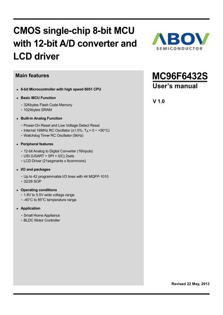
<strong>CMOS</strong> <strong>single</strong>-<strong>chip</strong> 8-<strong>bit</strong> <strong>MCU</strong><br />
<strong>with</strong> <strong>12</strong>-<strong>bit</strong> A/D <strong>converter</strong> <strong>and</strong><br />
<strong>LCD</strong> driver<br />
Main features<br />
• 8-<strong>bit</strong> Microcontroller <strong>with</strong> high speed 8051 CPU<br />
• Basic <strong>MCU</strong> Function<br />
– 32Kbytes Flash Code Memory<br />
– 1024bytes SRAM<br />
MC96F6432S<br />
User’s manual<br />
V 1.0<br />
• Built-in Analog Function<br />
– Power-On Reset <strong>and</strong> Low Voltage Detect Reset<br />
– Internal 16MHz RC Oscillator (±1.5%, T A = 0 ~ +50°C)<br />
– Watchdog Timer RC Oscillator (5kHz)<br />
• Peripheral features<br />
– <strong>12</strong>-<strong>bit</strong> Analog to Digital Converter (16inputs)<br />
– USI (USART + SPI + I2C) 2sets<br />
– <strong>LCD</strong> Driver (21segments x 8commons)<br />
• I/O <strong>and</strong> packages<br />
– Up to 42 programmable I/O lines <strong>with</strong> 44 MQFP-1010<br />
– 32/28 SOP<br />
• Operating conditions<br />
– 1.8V to 5.5V wide voltage range<br />
– -40°C to 85°C temperature range<br />
• Application<br />
– Small Home Appliance<br />
– BLDC Motor Controller<br />
Revised 22 May, 2013
ABOV Semiconductor Co., Ltd.<br />
MC96F6432S<br />
Revision history<br />
Version Date Revision list<br />
0.0 20<strong>12</strong>.08.24 Published this book.<br />
1.0 2013.05.22 Revised this book.<br />
Version 1.0<br />
Published by FAE team<br />
2013 ABOV Semiconductor Co. Ltd. all rights reserved.<br />
Additional information of this manual may be served by ABOV Semiconductor offices in Korea or distributors.<br />
ABOV Semiconductor reserves the right to make changes to any information here in at any time <strong>with</strong>out notice.<br />
The information, diagrams <strong>and</strong> other data in this manual are correct <strong>and</strong> reliable;<br />
however, ABOV Semiconductor is in no way responsible for any violations of patents or other rights of the third<br />
party generated by the use of this manual.<br />
2
MC96F6432S<br />
ABOV Semiconductor Co., Ltd.<br />
1 Overview<br />
1.1. Description<br />
The MC96F6432S is an advanced <strong>CMOS</strong> 8-<strong>bit</strong> microcontroller <strong>with</strong> 32Kbytes of FLASH. This is powerful<br />
microcontroller which provides a highly flexible <strong>and</strong> cost effective solution to many embedded control applications. This<br />
offers the following features: 32Kbytes of FLASH, 256bytes of IRAM, 768bytes of XRAM, general purpose I/O, basic<br />
interval timer, watchdog timer, 8/16-<strong>bit</strong> timer/counter, 16-<strong>bit</strong> PPG output, 8-<strong>bit</strong> PWM output, 10-<strong>bit</strong> PWM output, watch<br />
timer, buzzer driving port, SPI, USI, <strong>12</strong>-<strong>bit</strong> A/D <strong>converter</strong>, <strong>LCD</strong> driver, on-<strong>chip</strong> POR, LVR, LVI, on-<strong>chip</strong> oscillator <strong>and</strong><br />
clock circuitry. The MC96F6432S also supports power saving modes to reduce power consumption.<br />
Device Name FLASH XRAM IRAM ADC I/O PORT Package<br />
MC96F6432SQ<br />
16inputs 42 44 MQFP<br />
MC96F6332SD 32Kbytes 768bytes 256bytes <strong>12</strong>inputs 30 32 SOP<br />
MC96F6332SM 11inputs 26 28 SOP<br />
Table 1.1<br />
Ordering Information of MC96F6432S<br />
3
ABOV Semiconductor Co., Ltd.<br />
MC96F6432S<br />
1.2 Features<br />
• CPU<br />
– 8-<strong>bit</strong> CISC core (8051 Compatible)<br />
• ROM (FLASH) Capacity<br />
– 32Kbytes Flash <strong>with</strong> self-read <strong>and</strong> write capability<br />
– In-System Programming(ISP)<br />
– Endurance : 100,000times<br />
• 256bytes IRAM<br />
• 768bytes XRAM<br />
– (27bytes including <strong>LCD</strong> display RAM)<br />
• General Purpose I/O (GPIO)<br />
– Normal I/O : 9ports (P0[2:0], P5[5:0])<br />
– <strong>LCD</strong> shared I/O : 33ports (P0[7:3], P1, P2, P3, P4)<br />
• Timer/Counter<br />
– Basic Interval Timer (BIT) 8-<strong>bit</strong> × 1-ch<br />
– Watch Dog Timer (WDT) 8-<strong>bit</strong> × 1-ch<br />
– 5kHz internal RC oscillator<br />
– 8-<strong>bit</strong> × 1-ch (T0), 16-<strong>bit</strong> × 2-ch (T1/T2)<br />
– 8-<strong>bit</strong> × 2-ch (T3/T4) or 16-<strong>bit</strong> × 1-ch (T3)<br />
• Programmable Pulse Generation<br />
– Pulse generation (by T1/T2)<br />
– 8-<strong>bit</strong> PWM (by T0)<br />
– 6-ch 10-<strong>bit</strong> PWM for Motor (by T4)<br />
• Watch Timer (WT)<br />
– 3.91ms/0.25s/0.5s/1s /1min interval at 32.768kHz<br />
• Buzzer<br />
– 8-<strong>bit</strong> × 1-ch<br />
• SPI 2<br />
– 8-<strong>bit</strong> × 1-ch<br />
• USI0/1 (UART + SPI + I2C)<br />
– 8-<strong>bit</strong> UART × 2-ch, 8-<strong>bit</strong> SPI × 2-ch <strong>and</strong> I2C × 2-ch<br />
• <strong>12</strong>-<strong>bit</strong> A/D Converter<br />
– 16 Input channels<br />
• <strong>LCD</strong> Driver<br />
– 21segments <strong>and</strong> 8common terminals<br />
– Internal or external resistor bias<br />
– Two Internal Resistors Selectable<br />
– 1/2, 1/3, 1/4, 1/5, 1/6 <strong>and</strong> 1/8 duty selectable<br />
– Resistor Bias <strong>and</strong> 16-step contrast control<br />
• Low Voltage Indicator<br />
– 13 levels detect<br />
(2.00 / 2.10/ 2.20/ 2.32/ 2.44/ 2.59/ 2.75/ 2.93/ 3.14/<br />
3.38/ 3.67/ 4.00/ 4.40V)<br />
• Interrupt Sources<br />
– External Interrupts<br />
– (EXINT0~7, EINT8, EINT10, EINT11, EINT<strong>12</strong>) (<strong>12</strong>)<br />
– Timer(0/1/2/3/4) (5)<br />
– WDT (1)<br />
– BIT (1)<br />
– WT (1)<br />
– SPI 2 (1)<br />
– USI0/1 (6)<br />
– ADC (1)<br />
• Internal RC Oscillator<br />
– Internal RC frequency:<br />
16MHz ±1.5% (T A = 0 ~ +50°C)<br />
• Power Down Mode<br />
– STOP, IDLE mode<br />
• Operating Voltage <strong>and</strong> Frequency<br />
– 1.8V~ 5.5V (@32 ~ 38kHz <strong>with</strong> Crystal)<br />
– 1.8V~ 5.5V (@0.4 ~ 4.2MHz <strong>with</strong> Crystal)<br />
– 2.7V~ 5.5V (@0.4 ~ 10.0MHz<strong>with</strong> Crystal)<br />
– 3.0V~ 5.5V (@0.4 ~ <strong>12</strong>.0MHz <strong>with</strong> Crystal)<br />
– 1.8V~ 5.5V (@0.5 ~ 8.0MHz <strong>with</strong> Internal RC)<br />
– 2.0V~ 5.5V (@0.5 ~ 16.0MHz <strong>with</strong> Internal RC)<br />
– Voltage dropout <strong>converter</strong> included for core<br />
• Minimum Instruction Execution Time<br />
– <strong>12</strong>5ns (@16MHz main clock)<br />
– 61us (@t 32.768kHz sub clock)<br />
• Operating Temperature<br />
– –40 ~ +85℃<br />
• Oscillator Type<br />
– 0.4 - <strong>12</strong>MHz Crystal or Ceramic for main clock<br />
– 32.768kHz Crystal for sub clock<br />
• Package Type<br />
– 44 MQFP-1010<br />
– 32 SOP<br />
– 28 SOP<br />
– Pb-free pac<br />
• Power On Reset<br />
– Reset release level (1.4V)<br />
• Low Voltage Reset<br />
– 14 levels detect<br />
(1.60/ 2.00/ 2.10/ 2.20/ 2.32/ 2.44/ 2.59/ 2.75/ 2.93/<br />
3.14/ 3.38/ 3.67/ 4.00/ 4.40V)<br />
4
MC96F6432S<br />
1.3 Development tools<br />
–<br />
ABOV Semiconductor Co., Ltd.<br />
1.3.1 Compiler<br />
ABOV Semiconductor does not provide compiler. It is recommended that you consult a compier provider.<br />
The MC96F6432S core is Mentor 8051, <strong>and</strong> the ROM size is smaller than 64Kbytes.Therefore, developer can use the<br />
st<strong>and</strong>ard 8051 compiler from other providers.<br />
1.3.2 OCD(On-<strong>chip</strong> debugger) emulator <strong>and</strong> debugger<br />
The OCD (On Chip Debug) emulator supports ABOV Semiconductor’s 8051 series <strong>MCU</strong> emulation.The OCD interface<br />
uses two-wire connection between PC <strong>and</strong> <strong>MCU</strong> which is attached to user’s system. The OCD can read or change the<br />
value of <strong>MCU</strong> internal memory <strong>and</strong> I/O peripherals. And the OCD also controls <strong>MCU</strong> internal debugging logic, it means<br />
OCD controls emulation, step run, monitoring, etc.<br />
The OCD debugger program works on Microsoft-Windows NT, 2000, XP, Vista (32-<strong>bit</strong>) operating system.If you want to<br />
see more details, please refer to OCD debugger manual. You can download debugger S/W <strong>and</strong> manual from our website<br />
(http://www.abov.co.kr).<br />
Connection:<br />
– DSCL (MC96F6432 P01 port)<br />
– DSDA (MC96F6432 P00 port)<br />
Note) MC96F6432S does not support the OCD function. MC96F6432 should be used for debugging.<br />
OCD connector diagram: Connect OCD <strong>with</strong> user system<br />
1<br />
2 User VCC<br />
3 4<br />
5 6<br />
7 8<br />
User GND<br />
DSCL<br />
DSDA<br />
9<br />
10<br />
Figure 1.1<br />
debugger <strong>and</strong> pin description<br />
Subject MC96F6432S MC96F6432 (Evaluation <strong>chip</strong>)<br />
Internal <strong>LCD</strong> bias dividing resistor<br />
(Chapter 11.15 – <strong>LCD</strong> driver)<br />
Full-flash erase mode method<br />
(Chapter 15 – Flash memory)<br />
Table 1.2<br />
60kΩ <strong>and</strong> <strong>12</strong>0kΩ selectable<br />
– Added the IRSEL <strong>bit</strong> in the <strong>LCD</strong>CRL register<br />
– Added <strong>LCD</strong> contrast formula <strong>with</strong> <strong>12</strong>0kΩ<br />
Sector erase mode<br />
Difference between MC96F6432S <strong>and</strong> evaluation <strong>chip</strong> (MC96F6432)<br />
60kΩ only<br />
Sector <strong>and</strong> byte erase mode<br />
5
ABOV Semiconductor Co., Ltd.<br />
MC96F6432S<br />
OCD emulator: It can write code to <strong>MCU</strong> device too, because OCD debugger supports ISP (In System<br />
Programming).It does not require additional H/W, except developer’s target system.<br />
1.3.3 Programmer<br />
Single programmer:<br />
PGMplus USB: It programs <strong>MCU</strong> device directly.<br />
Figure 1.4<br />
PGMplusUSB(Single writer)<br />
St<strong>and</strong>alone PGMplus:<br />
It programs <strong>MCU</strong> device directly.<br />
Figure 1.5<br />
St<strong>and</strong>alone PGMplus(Single writer)<br />
6
MC96F6432S<br />
ABOV Semiconductor Co., Ltd.<br />
Gang programmer:<br />
It programs 8 <strong>MCU</strong> devices at once.So, it is mainly used in mass production factory.<br />
Gang programmer is st<strong>and</strong>alone type, it means it does not require host PC, after a program is downloaded from host<br />
PC to Gang programmer.<br />
Figure 1.6<br />
St<strong>and</strong>Alone Gang8 (for Mass Production)<br />
7
ABOV Semiconductor Co., Ltd.<br />
MC96F6432S<br />
1.4 MTP programming<br />
1.4.1 Overview<br />
The program memory of MC96F6432S is MTP Type. This flash is accessed by serial data format. There are four<br />
pins(DSCL, DSDA, VDD, <strong>and</strong> VSS) for programming/reading the flash.<br />
Pin name<br />
Main <strong>chip</strong><br />
pin name<br />
I/O<br />
During programming<br />
Description<br />
DSCL P01 I Serial clock pin. Input only pin.<br />
DSDA P00 I/O<br />
Serial data pin. Output port when reading <strong>and</strong> input port when programming.<br />
Can be assigned as input/push-pull output port.<br />
VDD, VSS VDD, VSS - Logic power supply pin.<br />
Table 1-3.<br />
Descriptions of pins which are used to programming/reading the Flash<br />
1.4.2 On-Board programming<br />
The MC96F6432S needs only four signal lines including VDD <strong>and</strong> VSS pins for programming FLASH <strong>with</strong> serial<br />
communication protocol. Therefore the on-board programming is possible if the programming signal lines are ready at<br />
the PCB of application board is designed.<br />
1.5.2.1 Circuit Design Guide<br />
At the FLASH programming, the programming tool needs 4 signal lines that areDSCL, DSDA, VDD, <strong>and</strong> VSS. When<br />
you design the PCB circuits, you should consider the usage of these signal lines for the on-board programming.<br />
Please be careful to design the related circuit of these signal pins because rising/falling timing of DSCL <strong>and</strong> DSDA is<br />
very important for proper programming.<br />
8
MC96F6432S<br />
ABOV Semiconductor Co., Ltd.<br />
PGM plus USB, Stan Alone PGM plus, Stan Alone Gang8<br />
DSCL(I)<br />
R1 (2kΩ ~ 5kΩ)<br />
To application circuit<br />
DSDA(I/O)<br />
R2 (2kΩ ~ 5kΩ)<br />
To application circuit<br />
VDD<br />
VSS<br />
NOTE)<br />
1. In on-board programming mode, very high-speed signal will be provided to pin DSCL <strong>and</strong> DSDA.<br />
And it will cause some damages to the application circuits connected to DSCL or DSDA port if the<br />
application circuit is designed as high speed response such as relay control circuit. If possible, the<br />
I/O configuration of DSDA, DSCL pins had better be set to input mode.<br />
2. The value of R1 <strong>and</strong> R2 is recommended value. It varies <strong>with</strong> circuit of system.<br />
Figure 1.7<br />
PCB design guide for on board programming<br />
9
ABOV Semiconductor Co., Ltd.<br />
MC96F6432S<br />
2 Block diagram<br />
Flash<br />
32KB<br />
CORE<br />
M8051<br />
XRAM<br />
768B<br />
IRAM<br />
256B<br />
General purpose I/O<br />
9 ports normal I/O<br />
33 ports <strong>LCD</strong> shared I/O<br />
Watchdog timer<br />
8 channels, 8-<strong>bit</strong><br />
32kHz, internal RC OSC<br />
Basic interval timer<br />
1 channel, 8-<strong>bit</strong><br />
On-<strong>chip</strong> debug<br />
In-system programming<br />
Power control<br />
Power on reset<br />
Low voltage reset<br />
Low voltage indicator<br />
Power down mode<br />
Clock generator<br />
16MHz, Internal RC OSC<br />
<strong>12</strong>MHz, Crystal OSC<br />
32.768kHz, Crystal OSC<br />
Timer / Counter<br />
1 channel, 8-<strong>bit</strong><br />
2 channels, 16-<strong>bit</strong><br />
2 channels, 8-<strong>bit</strong><br />
or 1 channel, 16-<strong>bit</strong><br />
<strong>LCD</strong> driver<br />
21 segments<br />
Buzzer<br />
1 channel, 8-<strong>bit</strong><br />
UART<br />
2 channels, 8-<strong>bit</strong><br />
ADC<br />
16 Input channels, <strong>12</strong>-<strong>bit</strong><br />
PWM<br />
6 channels<br />
SPI<br />
3 channels, 8-<strong>bit</strong><br />
I2C<br />
2 channels, 8-<strong>bit</strong><br />
Figure 2.1<br />
Block diagrom of MC96F6432<br />
10
MC96F6432S<br />
ABOV Semiconductor Co., Ltd.<br />
3 Pin assignment<br />
P03/SEG26/AN1/EINT1/PWM4AB<br />
P02/AN0/AVREF/EINT0/T4O/PWM4AA<br />
P01/T3O/DSCL<br />
P00/EC3/DSDA<br />
VDD<br />
VSS<br />
P50/XOUT<br />
P51/XIN<br />
P52/EINT8/EC0/BLNK<br />
P53/SXIN/T0O/PWM0O<br />
P54/SXOUT/EINT10<br />
P55/RESETB<br />
P40/VLC3/RXD0/SCL0/MISO0<br />
P41/VLC2/TXD0/SDA0/MOSI0<br />
P42/VLC1/SCK0<br />
P43/VLC0/SS0<br />
P37/COM0<br />
P36/COM1<br />
P35/COM2/SEG0<br />
P34/COM3/SEG1<br />
P33/COM4/SEG2<br />
P32/COM5/SEG3<br />
1<br />
2<br />
3<br />
4<br />
5<br />
6<br />
7<br />
8<br />
9<br />
10<br />
11<br />
44<br />
43<br />
42<br />
41<br />
40<br />
39<br />
38<br />
37<br />
36<br />
35<br />
MC96F6432SQ<br />
(44MQFP-1010)<br />
34<br />
33<br />
32<br />
31<br />
30<br />
29<br />
28<br />
27<br />
26<br />
25<br />
24<br />
23<br />
P04/SEG25/AN2/EINT2/PWM4BA<br />
P05/SEG24/AN3/EINT3/PWM4BB<br />
P06/SEG23/AN4/EINT4/PWM4CA<br />
P07/SEG22/AN5/EINT5/PWM4CB<br />
P17/SEG21/AN6/EINT6/SS2<br />
P16/SEG20/AN7/EINT7/SCK2<br />
P15/SEG19/AN8/MISO2<br />
P14/SEG18/AN9/MOSI2<br />
P13/SEG17/AN10/EC1/BUZO<br />
P<strong>12</strong>/SEG16/AN11/EINT11/T1O/PWM1O<br />
P11/SEG15/AN<strong>12</strong>/EINT<strong>12</strong>/T2O/PWM2O<br />
22<br />
21<br />
20<br />
19<br />
18<br />
17<br />
16<br />
15<br />
14<br />
13<br />
<strong>12</strong><br />
P10/SEG14/AN13/RXD1/SCL1/MISO1<br />
P20/SEG13/AN14/TXD1/SDA1/MOSI1<br />
P21/SEG<strong>12</strong>/AN15/SCK1<br />
P22/SEG11/SS1<br />
P23/SEG10<br />
P24/SEG9<br />
P25/SEG8<br />
P26/SEG7<br />
P27/SEG6<br />
P30/COM7/SEG5<br />
P31/COM6/SEG4<br />
NOTE)<br />
1. The programmer (PGMplus, Gang8) uses P0[1:0] pin as DSCL, DSDA.<br />
Figure 3.1<br />
MC96F6432SQ 44MQFP-1010 pin assignment<br />
11
ABOV Semiconductor Co., Ltd.<br />
MC96F6432S<br />
VSS<br />
P50/XOUT<br />
P51/XIN<br />
P52/EINT8/EC0/BLNK<br />
P53/SXIN/T0O/PWM0O<br />
P54/SXOUT/EINT10<br />
P55/RESETB<br />
P40/VLC3/RXD0/SCL0/MISO0<br />
P41/VLC2/TXD0/SDA0/MOSI0<br />
P42/VLC1/SCK0<br />
P33/COM4/SEG2<br />
P32/COM5/SEG3<br />
P31/COM6/SEG4<br />
P30/COM7/SEG5<br />
P27/SEG6<br />
P26/SEG7<br />
1<br />
2<br />
3<br />
4<br />
5<br />
6<br />
7<br />
8<br />
9<br />
10<br />
11<br />
<strong>12</strong><br />
13<br />
14<br />
15<br />
16<br />
MC96F6332SD<br />
(32-SOP)<br />
32<br />
31<br />
30<br />
29<br />
28<br />
27<br />
26<br />
25<br />
24<br />
23<br />
22<br />
21<br />
20<br />
19<br />
18<br />
17<br />
VDD<br />
P00/EC3/DSDA<br />
P01/T3O/DSCL<br />
P02/AN0/AVREF/EINT0/T4O/PWM4AA<br />
P03/SEG26/AN1/EINT1/PWM4AB<br />
P04/SEG25/AN2/EINT2/PWM4BA<br />
P05/SEG24/AN3/EINT3/PWM4BB<br />
P06/SEG23/AN4/EINT4/PWM4CA<br />
P07/SEG22/AN5/EINT5/PWM4CB<br />
P13/SEG17/AN10/EC1/BUZO<br />
P<strong>12</strong>/SEG16/AN11/EINT11/T1O/PWM1O<br />
P11/SEG15/AN<strong>12</strong>/EINT<strong>12</strong>/T2O/PWM2O<br />
P10/SEG14/AN13/RXD1/SCL1/MISO1<br />
P20/SEG13/AN14/TXD1/SDA1/MOSI1<br />
P21/SEG<strong>12</strong>/AN15/SCK1<br />
P22/SEG11/SS1<br />
NOTE)<br />
1. The programmer (PGMplus, Gang) uses P0[1:0] pin as DSCL, DSDA.<br />
2. The P14-P17, P23-P25, P34-P37 <strong>and</strong> P43 pins should be selected as a push-pull output or an input<br />
<strong>with</strong> pull-up resistor by software control when the 32-pin package is used.<br />
Figure 3.2<br />
MC96F6332SD 32SOP pin assignment<br />
VSS<br />
P50/XOUT<br />
P51/XIN<br />
P52/EINT8/EC0/BLNK<br />
P53/SXIN/T0O/PWM0O<br />
P54/SXOUT/EINT10<br />
P55/RESETB<br />
P40/VLC3/RXD0/SCL0/MISO0<br />
P41/VLC2/TXD0/SDA0/MOSI0<br />
P42/VLC1/SCK0<br />
P33/COM4/SEG2<br />
P32/COM5/SEG3<br />
P31/COM6/SEG4<br />
P30/COM7/SEG5<br />
1<br />
2<br />
3<br />
4<br />
5<br />
6<br />
7<br />
8<br />
9<br />
10<br />
11<br />
<strong>12</strong><br />
13<br />
14<br />
MC96F6332SM<br />
(28-SOP)<br />
28<br />
27<br />
26<br />
25<br />
24<br />
23<br />
22<br />
21<br />
20<br />
19<br />
18<br />
17<br />
16<br />
15<br />
VDD<br />
P00/EC3/DSDA<br />
P01/T3O/DSCL<br />
P02/AN0/AVREF/EINT0/T4O/PWM4AA<br />
P03/SEG26/AN1/EINT1/PWM4AB<br />
P04/SEG25/AN2/EINT2/PWM4BA<br />
P05/SEG24/AN3/EINT3/PWM4BB<br />
P06/SEG23/AN4/EINT4/PWM4CA<br />
P07/SEG22/AN5/EINT5/PWM4CB<br />
P<strong>12</strong>/SEG16/AN11/EINT11/T1O/PWM1O<br />
P11/SEG15/AN<strong>12</strong>/EINT<strong>12</strong>/T2O/PWM2O<br />
P10/SEG14/AN13/RXD1/SCL1/MISO1<br />
P20/SEG13/AN14/TXD1/SDA1/MOSI1<br />
P21/SEG<strong>12</strong>/AN15/SCK1<br />
NOTE)<br />
1. The programmer (PGMplus, Gang) uses P0[1:0] pin as DSCL, DSDA.<br />
2. The P13-P17, P22-P27, P34-P37 <strong>and</strong> P43 pins should be selected as a push-pull output or an input<br />
<strong>with</strong> pull-up resistor by software control when the 32-pin package is used.<br />
Figure 3.3<br />
MC96F6332SM 28SOP pinassignment<br />
<strong>12</strong>
MC96F6432S<br />
ABOV Semiconductor Co., Ltd.<br />
4 Package Diagram<br />
Figure 4.1<br />
44-Pin MQFPPackage<br />
13
ABOV Semiconductor Co., Ltd.<br />
MC96F6432S<br />
Figure 4.2<br />
32-Pin SOPPackage<br />
14
MC96F6432S<br />
ABOV Semiconductor Co., Ltd.<br />
Figure 4.3<br />
28-Pin SOPPackage<br />
15
ABOV Semiconductor Co., Ltd.<br />
MC96F6432S<br />
5 Pin Description<br />
PIN<br />
Name<br />
P00<br />
P01<br />
P02<br />
P03<br />
P04<br />
P05<br />
P06<br />
P07<br />
P10<br />
P11<br />
P<strong>12</strong><br />
P13<br />
P14<br />
P15<br />
P16<br />
P17<br />
P20<br />
P21<br />
P22<br />
P23<br />
P24<br />
P25<br />
P26<br />
P27<br />
P30<br />
P31<br />
P32<br />
P33<br />
P34<br />
P35<br />
P36<br />
P37<br />
P40<br />
P41<br />
P42<br />
P43<br />
Table 5-1.<br />
I/O Function @RESET Shared <strong>with</strong><br />
I/O<br />
I/O<br />
I/O<br />
I/O<br />
I/O<br />
Port 0 is a <strong>bit</strong>-programmable I/O port which can be<br />
configured as a Schmitt-trigger input, a push-pull<br />
output, or an open-drain output.<br />
A pull-up resistor can be specified in 1-<strong>bit</strong> unit.<br />
Port 1 is a <strong>bit</strong>-programmable I/O port which can be<br />
configured as a Schmitt-trigger input, a push-pull<br />
output, or an open-drain output.<br />
A pull-up resistor can be specified in 1-<strong>bit</strong> unit.<br />
The P14 – P17 are not in the 32-pin package. The<br />
P13 – P17 are not in the 28-pin package.<br />
Port 2 is a <strong>bit</strong>-programmable I/O port which can be<br />
configured as an input, a push-pull output, or an<br />
open-drain output.<br />
A pull-up resistor can be specified in 1-<strong>bit</strong> unit.<br />
The P23 – P25 are not in the 32-pin package.<br />
The P22 – P27 are not in the 28-pin package.<br />
Port 3 is a <strong>bit</strong>-programmable I/O port which can be<br />
configured as an input, a push-pull output.<br />
A pull-up resistor can be specified in 1-<strong>bit</strong> unit.<br />
The P34 – P37 are only in the 44-pin package.<br />
Port 4 is a <strong>bit</strong>-programmable I/O port which can be<br />
configured as an input, a push-pull output, or an<br />
open-drain output.<br />
A pull-up resistor can be specified in 1-<strong>bit</strong> unit.<br />
The P43 is only in the 44-pin package.<br />
Normal Pin Description<br />
Input<br />
Input<br />
Input<br />
Input<br />
Input<br />
EC3/DSDA<br />
T3O/DSCL<br />
AN0/AVREF/EINT0/T4O/PWM4AA<br />
SEG26/AN1/EINT1/PWM4AB<br />
SEG25/AN2/EINT2/PWM4BA<br />
SEG24/AN3/EINT3/PWM4BB<br />
SEG23/AN4/EINT4/PWM4CA<br />
SEG22/AN5/EINT5/PWM4CB<br />
SEG14/AN13/RXD1/SCL1/MISO1<br />
SEG15/AN<strong>12</strong>/EINT<strong>12</strong>/T2O/PWM2O<br />
SEG16/AN11/EINT11/T1O/PWM1O<br />
SEG17/AN10/EC1/BUZO<br />
SEG18/AN9/MOSI2<br />
SEG19/AN8/MISO2<br />
SEG20/AN7/EINT7/SCK2<br />
SEG21/AN6/EINT6/SS2<br />
SEG13/AN14/TXD1/SDA1/MOSI1<br />
SEG<strong>12</strong>/AN15/SCK1<br />
SEG11/SS1<br />
SEG10<br />
SEG9<br />
SEG8<br />
SEG7<br />
SEG6<br />
COM7/SEG5<br />
COM6/SEG4<br />
COM5/SEG3<br />
COM4/SEG2<br />
COM3/SEG1<br />
COM2/SEG0<br />
COM1<br />
COM0<br />
VLC3/RXD0/SCL0/MISO0<br />
VLC2/TXD0/SDA0/MOSI0<br />
VLC1/SCK0<br />
VLC0/SS0<br />
16
MC96F6432S<br />
ABOV Semiconductor Co., Ltd.<br />
PIN<br />
Name<br />
P50<br />
P51<br />
P52<br />
P53<br />
P54<br />
P55<br />
I/O Function @RESET Shared <strong>with</strong><br />
I/O<br />
Port 5 is a <strong>bit</strong>-programmable I/O port which can be<br />
configured as a Schmitt-trigger input or a push-pull<br />
output.<br />
A pull-up resistor can be specified in 1-<strong>bit</strong> unit.<br />
Input<br />
XOUT<br />
XIN<br />
EINT8/EC0/BLNK<br />
SXIN/T0O/PWM0O<br />
SXOUT/EINT10<br />
RESETB<br />
EINT0 I/O External interrupt input <strong>and</strong> Timer 3 capture input Input P02/AN0/AVREF/T4O/PWM4AA<br />
EINT1 I/O External interrupt input <strong>and</strong> Timer 4 capture input Input P03/SEG26/AN1/PWM4AB<br />
EINT2<br />
EINT3<br />
EINT4<br />
EINT5<br />
EINT6<br />
EINT7<br />
EINT8<br />
I/O External interrupt inputs Input<br />
P04/SEG25/AN2/PWM4BA<br />
P05/SEG24/AN3/PWM4BB<br />
P06/SEG23/AN4/PWM4CA<br />
P07/SEG22/AN5/PWM4CB<br />
P17/SEG21/AN6/SS2<br />
P16/SEG20/AN7/SCK2<br />
P52/EC0/BLNK<br />
EINT10 I/O External interrupt input <strong>and</strong> Timer 0 capture input Input P54/SXOUT<br />
EINT11 I/O External interrupt input <strong>and</strong> Timer 1 capture input Input P<strong>12</strong>/SEG16/AN11/T1O/PWM1O<br />
EINT<strong>12</strong> I/O External interrupt input <strong>and</strong> Timer 2 capture input Input P11/SEG15/AN<strong>12</strong>/T2O/PWM2O<br />
T0O I/O Timer 0 interval output Input P53/SXIN/PWM0O<br />
T1O I/O Timer 1 interval output Input P<strong>12</strong>/SEG16/AN11/EINT11/PWM1O<br />
T2O I/O Timer 2 interval output Input P11/SEG15/AN<strong>12</strong>/EINT<strong>12</strong>/PWM2O<br />
T3O I/O Timer 3 interval output Input P01/DSCL<br />
T4O I/O Timer 4 interval output Input P02/AN0/AVREF/EINT0/PWM4AA<br />
PWM0O I/O Timer 0 PWM output Input P53/SXIN/T0O<br />
PWM1O I/O Timer 1 PWM output Input P<strong>12</strong>/SEG16/AN11/EINT11/T1O<br />
PWM2O I/O Timer 2 PWM output Input P11/SEG15/AN<strong>12</strong>/EINT<strong>12</strong>/T2O<br />
PWM4AA<br />
PWM4AB<br />
PWM4BA<br />
PWM4BB<br />
PWM4CA<br />
PWM4CB<br />
I/O Timer 4 PWM outputs Input<br />
P02/AN0/AVREF/EINT0/T4O<br />
P03/SEG26/AN1/EINT1<br />
P04/SEG25/AN2/EINT2<br />
P05/SEG24/AN3/EINT3<br />
P06/SEG23/AN4/EINT4<br />
P07/SEG22/AN5/EINT5<br />
BLNK I/O External sync signal input for 6-ch PWMs Input P52/EINT8/EC0<br />
EC0 I/O Timer 0 event count input Input P52/EINT8/BLNK<br />
EC1 I/O Timer 1 event count input Input P13/SEG17/AN10<br />
EC3 I/O Timer 3 event count input Input P00/DSDA<br />
Table 5-2.<br />
Normal Pin Description (continue)<br />
17
ABOV Semiconductor Co., Ltd.<br />
MC96F6432S<br />
PIN<br />
Name<br />
I/O Function @RESET Shared <strong>with</strong><br />
BUZO I/O Buzzer signal output Input P13/SEG17/AN10/EC1<br />
SCK0 I/O Serial 0 clock input/output Input P42/VLC1<br />
SCK1 I/O Serial 1 clock input/output Input P21/SEG<strong>12</strong>/AN15<br />
SCK2 I/O Serial 2 clock input/output Input P16/SEG20/AN7/EINT7<br />
MOSI0 I/O SPI 0 master output, slave input Input P41/VLC2/TXD0/SDA0<br />
MOSI1 I/O SPI 1 master output, slave input Input P20/SEG13/AN14/TXD1/SDA1<br />
MOSI2 I/O SPI 2 master output, slave input Input P14/SEG18/AN9<br />
MISO0 I/O SPI 0 master input, slave output Input P40/VLC3/RXD0/SCL0<br />
MISO1 I/O SPI 1 master input, slave output Input P10/SEG14/AN13/RXD1/SCL1<br />
MISO2 I/O SPI 2 master input, slave output Input P15/SEG19/AN8<br />
SS0 I/O SPI 0 slave select input Input P43/VLC0<br />
SS1 I/O SPI 1 slave select input Input P22/SEG11<br />
SS2 I/O SPI 2 slave select input Input P17/SEG21/AN6/EINT6<br />
TXD0 I/O UART 0 data output Input P41/VLC2/SDA0/MOSI0<br />
TXD1 I/O UART 1 data output Input P20/SEG13/AN14/SDA1/MOSI1<br />
RXD0 I/O UART 0 data input Input P40/VLC3/SCL0/MISO0<br />
RXD1 I/O UART 1 data input Input P10/SEG14/AN13/SCL1/MISO1<br />
SCL0 I/O I2C 0 clock input/output Input P40/VLC3/RXD0/MISO0<br />
SCL1 I/O I2C 1 clock input/output Input P10/SEG14/AN13/RXD1/MISO1<br />
SDA0 I/O I2C 0 data input/output Input P41/VLC2/TXD0/MOSI0<br />
SDA1 I/O I2C 1 data input/output Input P20/SEG13/AN14/TXD1/MOSI1<br />
AVREF I/O A/D <strong>converter</strong> reference voltage Input P02/AN0/EINT0/T4O/PWM4AA<br />
AN0<br />
AN1<br />
AN2<br />
AN3<br />
AN4<br />
AN5<br />
AN6<br />
AN7<br />
AN8<br />
AN9<br />
AN10<br />
AN11<br />
AN<strong>12</strong><br />
AN13<br />
AN14<br />
AN15<br />
I/O A/D <strong>converter</strong> analog input channels Input<br />
P02/AVREF/EINT0/T4O/PWM4AA<br />
P03/SEG26/EINT1/PWM4AB<br />
P04/SEG25/EINT2/PWM4BA<br />
P05/SEG24/EINT3/PWM4BB<br />
P06/SEG23/EINT4/PWM4CA<br />
P07/SEG22/EINT5/PWM4CB<br />
P17/SEG21/EINT6/SS2<br />
P16/SEG20/EINT7/SCK2<br />
P15/SEG19/MISO2<br />
P14/SEG18/MOSI2<br />
P13/SEG17/EC1<br />
P<strong>12</strong>/SEG16/EINT11/T1O/PWM1O<br />
P11/SEG15/EINT<strong>12</strong>/T2O/PWM2O<br />
P10/SEG14/RXD1/SCL1/MISO1<br />
P20/SEG13/TXD1/SDA1/MOSI1<br />
P21/SEG<strong>12</strong>/SCK1<br />
Table 5-3.<br />
Normal Pin Description (continue)<br />
18
MC96F6432S<br />
ABOV Semiconductor Co., Ltd.<br />
PIN Name I/O Function @RESET Shared <strong>with</strong><br />
VLC0<br />
VLC1<br />
VLC2<br />
VLC3<br />
COM0<br />
COM1<br />
COM2–<br />
COM3<br />
COM4–<br />
COM7<br />
SEG0–<br />
SEG1<br />
SEG2–<br />
SEG5<br />
SEG6–<br />
SEG10<br />
SEG11<br />
SEG<strong>12</strong><br />
SEG13<br />
SEG14<br />
SEG15<br />
SEG16<br />
SEG17<br />
SEG18<br />
SEG19<br />
SEG20<br />
SEG21<br />
SEG22<br />
SEG23<br />
SEG24<br />
SEG25<br />
SEG26<br />
I/O <strong>LCD</strong> bias voltage pins Input<br />
I/O <strong>LCD</strong> common signal outputs Input<br />
I/O <strong>LCD</strong> segment signal outputs Input<br />
P43/SS0<br />
P42/SCK0<br />
P41/TXD0/SDA0/MOSI0<br />
P40/RXD0/SCL0/MISO0<br />
P37–P36<br />
P35–P34/SEG0–SEG1<br />
P33–P30/SEG2–SEG5<br />
P35–P34/COM2–COM3<br />
P33–P30/COM4–COM7<br />
P27–P23<br />
P22/SS1<br />
P21/SCK1/AN15<br />
P20/AN14/TXD1/SDA1/MOSI1<br />
P10/AN13/RXD1/SCL1/MISO1<br />
P11/AN<strong>12</strong>/EINT<strong>12</strong>/T2O/PWM2O<br />
P<strong>12</strong>/AN11/EINT11/T1O/PWM1O<br />
P13/AN10/EC1<br />
P14/AN9/MOSI2<br />
P15/AN8/MISO2<br />
P16/AN7/EINT7/SCK2<br />
P17/AN6/EINT6/SS2<br />
P07/AN5/EINT5/PWM4CB<br />
P06/AN4/EINT4/PWM4CA<br />
P05/AN3/EINT3/PWM4BB<br />
P04/AN2/EINT2/PWM4BA<br />
P03/AN1/EINT1/PWM4AB<br />
Table 5-4.<br />
Normal Pin Description (continue)<br />
19
ABOV Semiconductor Co., Ltd.<br />
MC96F6432S<br />
PIN<br />
Name<br />
I/O Function @RESET Shared <strong>with</strong><br />
RESETB I/O<br />
System reset pin <strong>with</strong> a pull-up resistor when it is<br />
selected as the RESETB by CONFIGURE OPTION<br />
Input P55<br />
DSDA I/O In-system programming data input/output Input P00/EC3<br />
DSCL I/O In-system programming clock input Input P01/T3O<br />
XIN<br />
XOUT<br />
SXIN<br />
SXOUT<br />
VDD,<br />
VSS<br />
I/O Main oscillator pins Input<br />
I/O Sub oscillator pins Input<br />
– Power input pins – –<br />
P51<br />
P50<br />
P53/T0O/PWM0O<br />
P54/EINT10<br />
Table 5-5.<br />
Normal Pin Description (continue)<br />
NOTE)<br />
1. The P14–P17, P23–P25, P34–P37, <strong>and</strong> P43 are not in the 32-pin package.<br />
2. The P13–P17, P22–P27, P34–P37, <strong>and</strong> P43 are not in the 28-pin package.<br />
3. The P55/RESETB pin is configured as one of the P55 <strong>and</strong> RESETB pin by the “CONFIGURE OPTION.”<br />
4. If the P00/EC3/DSDA <strong>and</strong> P01/T3O/DSCL pins are connected to the programmer during power-on reset,<br />
the pins are automatically configured as In-system programming pins.<br />
5. The P00/EC3/DSDA <strong>and</strong> P01/T3O/DSCL pins are configured as inputs <strong>with</strong> internal pull-up resistor<br />
only during the reset or power-on reset.<br />
6. The P50/XOUT, P51/XIN, P53/SXINT/T0O/PWM0O, <strong>and</strong> P54/SXOUT/EINT10 pins are configured as<br />
a function pin by software control.<br />
20
MC96F6432S<br />
ABOV Semiconductor Co., Ltd.<br />
6 Port Structures<br />
6.1 General Purpose I/O Port<br />
Level Shift (1.8V to ExtVDD)<br />
Level Shift (ExtVDD to 1.8V)<br />
VDD<br />
PULL-UP<br />
REGISTER<br />
OPEN DRAIN<br />
REGISTER<br />
VDD<br />
VDD<br />
DATA<br />
REGISTER<br />
SUB-FUNC DATA OUTPUT<br />
X<br />
U<br />
M<br />
0<br />
1<br />
PAD<br />
SUB-FUNC ENABLE<br />
SUB-FUNC DIRECTION<br />
DIRECTION<br />
REGISTER<br />
X<br />
U<br />
M<br />
1<br />
0<br />
PORTx INPUT or<br />
SUB-FUNC DATA INPUT<br />
<strong>CMOS</strong> or<br />
Schmitt Level<br />
Input<br />
ANALOG CHANNEL<br />
ENABLE<br />
ANALOG INPUT<br />
Figure 6.1<br />
General Purpose I/O Port<br />
21
ABOV Semiconductor Co., Ltd.<br />
MC96F6432S<br />
6.2 External Interrupt I/O Port<br />
Level Shift (1.8V to ExtVDD)<br />
Level Shift (ExtVDD to 1.8V)<br />
VDD<br />
PULL-UP<br />
REGISTER<br />
OPEN DRAIN<br />
REGISTER<br />
VDD<br />
VDD<br />
DATA<br />
REGISTER<br />
SUB-FUNC DATA OUTPUT<br />
X<br />
U<br />
M<br />
0<br />
1<br />
PAD<br />
SUB-FUNC ENABLE<br />
SUB-FUNC DIRECTION<br />
DIRECTION<br />
REGISTER<br />
X<br />
U<br />
M<br />
1<br />
0<br />
VDD<br />
EXTERNAL<br />
INTERRUPT<br />
Q<br />
D<br />
INTERRUPT<br />
ENABLE<br />
CP<br />
r<br />
POLARITY<br />
REG.<br />
FLAG<br />
CLEAR<br />
<strong>CMOS</strong> or<br />
Schmitt Level<br />
Input<br />
PORTx INPUT or<br />
SUB-FUNC DATA INPUT<br />
X<br />
U<br />
M<br />
0<br />
1<br />
Q<br />
D<br />
ANALOG CHANNEL<br />
ENABLE<br />
DEBOUNCE<br />
ENABLE<br />
CP<br />
r<br />
DEBOUNCE<br />
CLK<br />
ANALOG INPUT<br />
Figure 6.2<br />
External Interrupt I/O Port<br />
22
MC96F6432S<br />
ABOV Semiconductor Co., Ltd.<br />
7 Electrical Characteristics<br />
7.1 Absolute Maximum Ratings<br />
Parameter Symbol Rating Unit Note<br />
Supply Voltage VDD -0.3~+6.5 V –<br />
V I -0.3~VDD+0.3 V<br />
V O -0.3~VDD+0.3 V<br />
Voltage on any pin <strong>with</strong> respect to VSS<br />
Normal Voltage Pin<br />
I OH 10 mA Maximum current output sourced by (I OH per I/O pin)<br />
∑I OH 80 mA Maximum current (∑I OH)<br />
I OL 60 mA Maximum current sunk by (I OL per I/O pin)<br />
∑I OL <strong>12</strong>0 mA Maximum current (∑I OL)<br />
Total Power Dissipation P T 600 mW –<br />
Storage Temperature T STG -65~+150 °C –<br />
Table 7.1<br />
Absolute Maximum Ratings<br />
NOTE)<br />
1. Stresses beyond those listed under “Absolute Maximum Ratings” may cause permanent damage to the<br />
device. This is a stress rating only <strong>and</strong> functional operation of the device at any other conditions beyond<br />
those indicated in the operational sections of this specification is not implied. Exposure to absolute<br />
maximum rating conditions for extended periods may affect device reliability.<br />
7.2 Recommended Operating Conditions<br />
(T A=-40°C ~ +85°C)<br />
Parameter Symbol Conditions MIN TYP MAX Unit<br />
f X= 32 ~ 38kHz SX-tal 1.8 – 5.5<br />
f X= 0.4 ~ 4.2MHz<br />
1.8 – 5.5<br />
Operating Voltage<br />
VDD<br />
f X= 0.5 ~ 8MHz<br />
1.8 – 5.5<br />
Internal RC<br />
f X= 0.5 ~16MHz 2.0 – 5.5<br />
f X= 0.4 ~10MHz X-tal 2.7 – 5.5<br />
f X= 0.4 ~<strong>12</strong>MHz 3.0 – 5.5<br />
V<br />
Operating Temperature T OPR VDD=1.8~5.5V -40 – 85 °C<br />
Table 7.2<br />
Recommended Operating Conditions<br />
23
ABOV Semiconductor Co., Ltd.<br />
MC96F6432S<br />
7.3 A/D Converter Characteristics<br />
(T A=-40°C ~ +85°C, VDD=1.8V ~ 5.5V, VSS=0V)<br />
Parameter Symbol Conditions MIN TYP MAX Unit<br />
Resolution – – –- <strong>12</strong> – <strong>bit</strong><br />
Integral Linear Error<br />
ILE<br />
– – ±6<br />
Differential Linearity Error DLE AVREF= 2.7V – 5.5V<br />
– – ±1<br />
Zero Offset Error ZOE fx= 8MHz<br />
– – ±5<br />
Full Scale Error FSE – – ±5<br />
Conversion Time t CON <strong>12</strong>-<strong>bit</strong> resolution, 8MHz 20 – – us<br />
Analog Input Voltage V AN – VSS – AVREF<br />
Analog Reference Voltage AVREF – 1.8 – VDD<br />
Analog Input Leakage Current I AN AVREF=5.<strong>12</strong>V – – 2 uA<br />
ADC Operating Current<br />
I ADC<br />
LSB<br />
Enable<br />
– 1 2 mA<br />
VDD=5.<strong>12</strong>V<br />
Disable – – 0.1 uA<br />
V<br />
Table 7.3<br />
A/D Converter Characteristics<br />
NOTE)<br />
1. Zero offset error is the difference between 000000000000 <strong>and</strong> the converted output for zero input voltage<br />
(VSS).<br />
2. Full scale error is the difference between 111111111111 <strong>and</strong> the converted output for full-scale input<br />
voltage (AVREF).<br />
7.4 Power-On Reset Characteristics<br />
(T A=-40°C ~ +85°C, VDD=1.8V ~ 5.5V, VSS=0V)<br />
Parameter Symbol Conditions MIN TYP MAX Unit<br />
RESET Release Level V POR – – 1.4 – V<br />
VDD Voltage Rising Time t R – 0.05 – 30.0 V/ms<br />
POR Current I POR – – 0.2 – uA<br />
Table 7.4<br />
Power-on Reset Characteristics<br />
24
MC96F6432S<br />
ABOV Semiconductor Co., Ltd.<br />
7.5 Low Voltage Reset <strong>and</strong> Low Voltage Indicator Characteristics<br />
(T A=-40°C ~ +85°C, VDD=1.8V ~ 5.5V, VSS=0V)<br />
Parameter Symbol Conditions MIN TYP MAX Unit<br />
Detection Level<br />
V LVR<br />
V LVI<br />
The LVR can select all levels but LVI<br />
can select other levels except 1.60V<br />
– 1.60 1.79<br />
1.85 2.00 2.15<br />
1.95 2.10 2.25<br />
2.05 2.20 2.35<br />
2.17 2.32 2.47<br />
2.29 2.44 2.59<br />
2.39 2.59 2.79<br />
2.55 2.75 2.95<br />
2.73 2.93 3.13<br />
2.94 3.14 3.34<br />
3.18 3.38 3.58<br />
3.37 3.67 3.97<br />
3.70 4.00 4.30<br />
4.10 4.40 4.70<br />
Hysteresis △V – – 50 150 mV<br />
Minimum Pulse Width t LW – 100 – – us<br />
LVR <strong>and</strong> LVI Current<br />
I BL<br />
Enable (Both) VDD= 3V, – 14.0 24.0<br />
Enable (One of two) RUN Mode – 10.0 18.0<br />
Disable (Both) VDD= 3V – – 0.1<br />
V<br />
uA<br />
Table 7.5<br />
LVR <strong>and</strong> LVI Characteristics<br />
7.6 High Internal RC Oscillator Characteristics<br />
(T A=-40°C ~ +85°C, VDD=1.8V ~ 5.5V, VSS=0V)<br />
Parameter Symbol Conditions MIN TYP MAX Unit<br />
Frequency f IRC V DD = 2.0 – 5.5V – 16 – MHz<br />
Tolerance –<br />
T A = 0°C to +50°C<br />
With 0.1uF<br />
±1.5<br />
T A = -20°C to +85°C Bypass<br />
– – ±2.5<br />
T A = -40°C to +85°C<br />
capacitor<br />
±3.5<br />
Clock Duty Ratio TOD – 40 50 60 %<br />
Stabilization Time T HFS – – – 100 us<br />
IRC Current<br />
I IRC<br />
Enable – 0.2 – mA<br />
Disable – – 0.1 uA<br />
%<br />
Table 7.6<br />
High Internal RC Oscillator Characteristics<br />
NOTE)<br />
1. A 0.1uF bypass capacitor should be connected to VDD <strong>and</strong> VSS.<br />
7.7 Internal Watch-Dog Timer RC Oscillator Characteristics<br />
(T A=-40°C ~ +85°C, VDD=1.8V ~ 5.5V, VSS=0V)<br />
Parameter Symbol Conditions MIN TYP MAX Unit<br />
Frequency f WDTRC – 2 5 10 kHz<br />
Stabilization Time t WDTS – – – 1 ms<br />
WDTRC Current<br />
I WDTRC<br />
Enable – 1 –<br />
Disable – – 0.1<br />
uA<br />
Table 7.7<br />
Internal WDTRC Oscillator Characteristics<br />
25
ABOV Semiconductor Co., Ltd.<br />
MC96F6432S<br />
7.8 <strong>LCD</strong> Voltage Characteristics<br />
(T A=-40°C ~ +85°C, VDD=1.8V ~ 5.5V, VSS=0V)<br />
Parameter Symbol Conditions MIN TYP MAX Unit<br />
<strong>LCD</strong> Voltage<br />
<strong>LCD</strong> Mid Bias<br />
Voltage(note)<br />
<strong>LCD</strong> Driver<br />
Output<br />
Impedance<br />
<strong>LCD</strong> Bias<br />
Dividing Resistor<br />
V LC0<br />
<strong>LCD</strong> contrast disabled,1/4 bias Typx0.95 VDD Typx1.05 V<br />
<strong>LCD</strong><br />
contrast<br />
enabled,<br />
1/4 bias,<br />
R<strong>LCD</strong>1,<br />
No panel<br />
load<br />
<strong>LCD</strong>CCR=00H<br />
<strong>LCD</strong>CCR=01H<br />
<strong>LCD</strong>CCR=02H<br />
<strong>LCD</strong>CCR=03H<br />
<strong>LCD</strong>CCR=04H<br />
<strong>LCD</strong>CCR=05H<br />
<strong>LCD</strong>CCR=06H<br />
<strong>LCD</strong>CCR=07H<br />
<strong>LCD</strong>CCR=08H<br />
<strong>LCD</strong>CCR=09H<br />
<strong>LCD</strong>CCR=0AH<br />
<strong>LCD</strong>CCR=0BH<br />
<strong>LCD</strong>CCR=0CH<br />
<strong>LCD</strong>CCR=0DH<br />
<strong>LCD</strong>CCR=0EH<br />
<strong>LCD</strong>CCR=0FH<br />
Typx0.9<br />
VDDx16/31<br />
VDDx16/30<br />
VDDx16/29<br />
VDDx16/28<br />
VDDx16/27<br />
VDDx16/26<br />
VDDx16/25<br />
VDDx16/24<br />
VDDx16/23<br />
VDDx16/22<br />
VDDx16/21<br />
VDDx16/20<br />
VDDx16/19<br />
VDDx16/18<br />
VDDx16/17<br />
VDDx16/16<br />
Typx1.1<br />
V LC1<br />
VDD=2.7V to 5.5V,<br />
Typ-0.2 3/4xVLC0 Typ+0.2<br />
V LC2 <strong>LCD</strong> clock = 0Hz,<br />
Typ-0.2 2/4xVLC0 Typ+0.2<br />
V LC3<br />
1/4 bias, No panel load<br />
Typ-0.2 1/4xVLC0 Typ+0.2<br />
R LO V<strong>LCD</strong>=3V, ILOAD=±10uA – 5 10<br />
R <strong>LCD</strong>1<br />
40 60 80<br />
TA = 25°C<br />
R <strong>LCD</strong>2 80 <strong>12</strong>0 160<br />
V<br />
V<br />
kΩ<br />
Table 7.8<br />
<strong>LCD</strong> Voltage Characteristics<br />
NOTE)<br />
1. It is middle output voltage when the VDD <strong>and</strong> the V LC0 node are connected.<br />
26
MC96F6432S<br />
ABOV Semiconductor Co., Ltd.<br />
7.9 DC Characteristics<br />
(T A= -40°C ~ +85°C, VDD= 1.8V ~ 5.5V, VSS= 0V, f XIN= <strong>12</strong>MHz)<br />
Parameter Symbol Conditions MIN TYP MAX Unit<br />
Input High Voltage<br />
Input Low Voltage<br />
Output High<br />
Voltage<br />
Output Low Voltage<br />
Input High Leakage<br />
Current<br />
Input Low Leakage<br />
Current<br />
Pull-Up Resistor<br />
OSC feedback<br />
resistor<br />
Table 7.9<br />
V IH1 P0, P1,P5, RESETB 0.8VDD – VDD V<br />
V IH2 All input pins except V IH1 0.7VDD – VDD V<br />
V IL1 P0, P1,P5, RESETB – – 0.2VDD V<br />
V IL2 All input pins except V IL1 – – 0.3VDD V<br />
V OH<br />
VDD=4.5V, I OH=-2mA,<br />
All output ports;<br />
VDD-1.0 – – V<br />
V OL1<br />
VDD=4.5V, I OL= 10mA;<br />
All output ports except V OL2<br />
– – 1.0<br />
V OL2<br />
VDD=4.5V, I OL= 15mA;<br />
P1<br />
– – 1.0 V<br />
I IH All input ports – – 1 uA<br />
I IL All input ports -1 – – uA<br />
R PU1<br />
R PU2<br />
R X1<br />
R X2<br />
DC Characteristics<br />
VI=0V,<br />
VDD=5.0V 25 50 100<br />
T A= 25°C<br />
All Input ports VDD=3.0V 50 100 200<br />
VI=0V,<br />
VDD=5.0V 150 250 400<br />
T A= 25°C<br />
RESETB<br />
VDD=3.0V 300 500 700<br />
XIN= VDD, XOUT= VSS<br />
T A= 25°C, VDD= 5V<br />
600 <strong>12</strong>00 2000<br />
SXIN=VDD, SXOUT=VSS<br />
T A= 25°C, VDD=5V<br />
2500 5000 10000<br />
kΩ<br />
kΩ<br />
kΩ<br />
(T A= -40°C ~ +85°C, VDD= 1.8V ~ 5.5V, VSS= 0V, f XIN= <strong>12</strong>MHz)<br />
Parameter Symbol Condition MIN TYP MAX Unit<br />
Supply Current<br />
I DD1<br />
(RUN)<br />
f XIN= <strong>12</strong>MHz, VDD= 5V±10% – 3.0 6.0<br />
f XIN= 10MHz, VDD= 3V±10% – 2.2 4.4<br />
f IRC= 16MHz, VDD= 5V±10% – 3.0 6.0<br />
f XIN= <strong>12</strong>MHz, VDD= 5V±10% – 2.0 4.0<br />
I DD2<br />
(IDLE)<br />
f XIN= 10MHz, VDD= 3V±10% – 1.3 2.6 mA<br />
f IRC= 16MHz, VDD= 5V±10% – 1.5 3.0<br />
I DD3<br />
f XIN=32.768kHz Sub RUN – 60.0 90.0 uA<br />
VDD= 3V±10%<br />
I DD4 T A= 25°C<br />
Sub IDLE – 8.0 16.0 uA<br />
I DD5 STOP, VDD= 5V±10%, T A= 25°C – 0.5 3.0 uA<br />
mA<br />
Table 7.10<br />
DC Characteristics(Continued)<br />
NOTE)<br />
1. Where the f XIN is an external main oscillator, f SUB is an external sub oscillator, the f IRC is an internal RC<br />
oscillator, <strong>and</strong> the fx is the selected system clock.<br />
2. All supply current items don’t include the current of an internal Watch-dog timer RC (WDTRC) oscillator<br />
<strong>and</strong> a peripheral block.<br />
3. All supply current items include the current of the power-on reset (POR) block.<br />
27
ABOV Semiconductor Co., Ltd.<br />
MC96F6432S<br />
7.10 AC Characteristics<br />
(T A= -40°C ~ +85°C, VDD= 1.8V ~ 5.5V)<br />
Parameter Symbol Conditions MIN TYP MAX Unit<br />
RESETB input low width t RSL Input, VDD= 5V 10 – – us<br />
Interrupt input high, low width<br />
External Counter Input High,<br />
Low Pulse Width<br />
External Counter Transition Time<br />
Table 7.11<br />
AC Characteristics<br />
t INTH,<br />
t INTL<br />
tECWH,<br />
tECWL<br />
tREC,<br />
tFEC<br />
All interrupt, VDD= 5V 200 – –<br />
ECn, VDD = 5V (n= 0, 1, 3) 200 – –<br />
ECn, VDD = 5V (n= 0, 1, 3) 20 – –<br />
ns<br />
tIWL<br />
tIWH<br />
External<br />
Interrupt<br />
0.8VDD<br />
0.2VDD<br />
tRST<br />
RESETB<br />
0.2VDD<br />
tECWL<br />
tECWH<br />
ECn<br />
tFEC<br />
tREC<br />
0.8VDD<br />
0.2VDD<br />
Figure 7.1<br />
AC Timing<br />
28
MC96F6432S<br />
ABOV Semiconductor Co., Ltd.<br />
7.11 SPI0/1/2 Characteristics<br />
(T A=-40°C– +85°C, VDD=1.8V – 5.5V)<br />
Parameter Symbol Conditions MIN TYP MAX Unit<br />
Output Clock Pulse Period<br />
Internal SCK source 200 – –<br />
tSCK<br />
Input Clock Pulse Period External SCK source 200 – –<br />
Output Clock High, Low Pulse Width tSCKH, Internal SCK source 70 – –<br />
Input Clock High, Low Pulse Width tSCKL External SCK source 70 – –<br />
First Output Clock Delay Time tFOD Internal/External SCK source 100 – –<br />
Output Clock Delay Time tDS – – – 50<br />
Input Setup Time tDIS – 100 – –<br />
Input Hold Time tDIH – 150 – –<br />
ns<br />
Table 7.<strong>12</strong><br />
SPI0/1/2 Characteristics<br />
SSn<br />
(Output/Input)<br />
SCKn<br />
(CPOLn=0)<br />
(Output/Input)<br />
tFOD<br />
tSCKL<br />
tSCK<br />
tSCKH<br />
0.8VDD<br />
0.2VDD<br />
SCKn<br />
(CPOLn=1)<br />
(Output/Input)<br />
tDIS<br />
tDIH<br />
MISOn/MOSIn<br />
(Data Input)<br />
MSB<br />
LSB<br />
tDS<br />
MISOn/MOSIn<br />
(Data Output)<br />
MSB<br />
LSB<br />
NOTE) n =0, 1 <strong>and</strong> 2<br />
Figure 7.2<br />
SPI0/1/2 Timing<br />
29
ABOV Semiconductor Co., Ltd.<br />
MC96F6432S<br />
7.<strong>12</strong> UART0/1 Characteristics<br />
(T A=-40°C ~ +85°C, VDD=1.8V ~ 5.5V, f XIN=11.1MHz)<br />
Parameter Symbol MIN TYP MAX Unit<br />
Serial port clock cycle time t SCK <strong>12</strong>50 t CPU x 16 1650 ns<br />
Output data setup to clock rising edge t S1 590 t CPU x 13 – ns<br />
Clock rising edge to input data valid t S2 – – 590 ns<br />
Output data hold after clock rising edge t H1 t CPU- 50 t CPU – ns<br />
Input data hold after clock rising edge t H2 0 – – ns<br />
Serial port clock High, Low level width t HIGH,t LOW 470 t CPU x 8 970 ns<br />
Table 7.13<br />
UART0/1 Characteristics<br />
tSCK<br />
tHIGH<br />
tLOW<br />
Figure 7.3<br />
Waveform for UART0/1 Timing Characteristics<br />
tSCK<br />
Shift Clock<br />
tS1<br />
Data Out D0<br />
D1 D2 D3 D4 D5 D6 D7<br />
tS2<br />
tH1<br />
tH2<br />
Data In Valid<br />
Valid Valid Valid Valid Valid Valid Valid<br />
Figure 7.4<br />
Timing Waveform for the UART0/1 Module<br />
30
MC96F6432S<br />
ABOV Semiconductor Co., Ltd.<br />
7.13 I2C0/1 Characteristics<br />
(T A=-40°C ~ +85°C, VDD=1.8V ~ 5.5V)<br />
Parameter<br />
Symbol<br />
St<strong>and</strong>ard Mode<br />
High-Speed Mode<br />
MIN MAX MIN MAX<br />
Unit<br />
Clock frequency tSCL 0 100 0 400 kHz<br />
Clock High Pulse Width tSCLH 4.0 – 0.6 –<br />
Clock Low Pulse Width tSCLL 4.7 – 1.3 –<br />
Bus Free Time tBF 4.7 – 1.3 –<br />
Start Condition Setup Time tSTSU 4.7 – 0.6 –<br />
Start Condition Hold Time tSTHD 4.0 – 0.6 – us<br />
Stop Condition Setup Time tSPSU 4.0 – 0.6 –<br />
Stop Condition Hold Time tSPHD 4.0 – 0.6 –<br />
Output Valid from Clock tVD 0 – 0 –<br />
Data Input Hold Time tDIH 0 – 0 1.0<br />
Data Input Setup Time tDIS 250 – 100 – ns<br />
Table 7.14<br />
I2C0/1 Characteristics<br />
tSCL<br />
tSTSU<br />
tSCLH<br />
tSCLL<br />
tDIH<br />
tSPSU<br />
SCLn<br />
tSPHD<br />
SDAn<br />
SDAn<br />
Out<br />
tSTHD<br />
tVD<br />
tVD<br />
tDIS<br />
tBF<br />
NOTE) n= 0, <strong>and</strong> 1<br />
Figure 7.5<br />
I2C0/1 Timing<br />
31
ABOV Semiconductor Co., Ltd.<br />
MC96F6432S<br />
7.14 Data Retention Voltage in Stop Mode<br />
(T A=-40°C ~ +85°C, VDD=1.8V ~ 5.5V)<br />
Parameter Symbol Conditions MIN TYP MAX Unit<br />
Data retention supply voltage V DDDR – 1.8 – 5.5 V<br />
Data retention supply current I DDDR<br />
VDDR= 1.8V,<br />
(T A= 25°C),<br />
Stop mode<br />
– – 1 uA<br />
Table 7.15<br />
Data Retention Voltage in Stop Mode<br />
~<br />
Stop Mode<br />
Data Retention<br />
Idle Mode<br />
(Watchdog Timer Active)<br />
Normal<br />
Operating Mode<br />
V DD<br />
~<br />
VDDDR<br />
Execution of<br />
STOP Instruction<br />
0.8VDD<br />
INT Request<br />
tWAIT<br />
NOTE: tWAIT is the same as (the selected <strong>bit</strong> overflow of BIT) X 1/(BIT Clock)<br />
Figure 7.6<br />
Stop Mode Release Timing when Initiated by an Interrupt<br />
RESET<br />
Occurs<br />
~<br />
Stop Mode<br />
Oscillation<br />
Stabillization Time<br />
Data Retention<br />
Normal<br />
Operating Mode<br />
VDD<br />
~<br />
VDDDR<br />
RESETB<br />
Execution of<br />
STOP Instruction<br />
0.2VDD<br />
0.8VDD<br />
TWAIT<br />
NOTE : tWAIT is the same as (4096 X 4 X 1/fx) (16.4ms @ 1MHz)<br />
Figure 7.7<br />
Stop Mode Release Timing when Initiated by RESETB<br />
32
MC96F6432S<br />
ABOV Semiconductor Co., Ltd.<br />
7.15 Internal Flash Rom Characteristics<br />
(T A=-40°C ~ +85°C, VDD=1.8V ~ 5.5V, VSS= 0V)<br />
Parameter Symbol Condition MIN TYP MAX Unit<br />
Sector Write Time t FSW – – 2.5 2.7<br />
Sector Erase Time t FSE – – 2.5 2.7 ms<br />
Hard-Lock Time t FHL – – 2.5 2.7<br />
Page Buffer Reset Time t FBR – – – 5 us<br />
Flash Programming Frequency f PGM – 0.4 – – MHz<br />
Endurance of Write/Erase NF WE – – – 100,000 times<br />
Table 7.16<br />
Internal Flash Rom Characteristics<br />
NOTE)<br />
1. During a flash operation, SCLK[1:0] of SCCR must be set to “00” or “01” (INT-RC OSC or Main X-TAL for<br />
system clock).<br />
7.16 Input/Output Capacitance<br />
(T A=-40°C ~ +85°C, VDD=0V)<br />
Parameter Symbol Condition MIN TYP MAX Unit<br />
Input Capacitance<br />
Output Capacitance<br />
I/O Capacitance<br />
C IN<br />
C OUT<br />
C IO<br />
fx= 1MHz<br />
Unmeasured pins are<br />
connected to VSS<br />
– – 10 pF<br />
Table 7.17<br />
Input/Output Capacitance<br />
33
ABOV Semiconductor Co., Ltd.<br />
MC96F6432S<br />
7.17 Main Clock Oscillator Characteristics<br />
Crystal<br />
(T A=-40°C ~ +85°C, VDD=1.8V ~ 5.5V)<br />
Oscillator Parameter Condition MIN TYP MAX Unit<br />
Ceramic Oscillator<br />
External Clock<br />
Main oscillation frequency<br />
Main oscillation frequency<br />
XIN input frequency<br />
1.8V – 5.5V 0.4 – 4.2<br />
2.7V – 5.5V 0.4 – 10.0<br />
3.0V – 5.5V 0.4 – <strong>12</strong>.0<br />
1.8V – 5.5V 0.4 – 4.2<br />
2.7V – 5.5V 0.4 – 10.0<br />
3.0V – 5.5V 0.4 – <strong>12</strong>.0<br />
1.8V – 5.5V 0.4 – 4.2<br />
2.7V – 5.5V 0.4 – 10.0<br />
3.0V – 5.5V 0.4 – <strong>12</strong>.0<br />
MHz<br />
MHz<br />
MHz<br />
Table 7.18<br />
Main Clock Oscillator Characteristics<br />
XIN<br />
XOUT<br />
C1<br />
C2<br />
Figure 7.8<br />
Crystal/Ceramic Oscillator<br />
XIN<br />
XOUT<br />
External<br />
Clock<br />
Source<br />
Open<br />
Figure 7.9<br />
External Clock<br />
34
MC96F6432S<br />
ABOV Semiconductor Co., Ltd.<br />
7.18 Sub Clock Oscillator Characteristics<br />
(T A=-40°C ~ +85°C, VDD=1.8V ~ 5.5V)<br />
Oscillator Parameter Condition MIN TYP MAX Unit<br />
Crystal<br />
Sub oscillation frequency<br />
32 32.768 38 kHz<br />
1.8V – 5.5V<br />
External Clock SXIN input frequency 32 – 100 kHz<br />
Table 7.19<br />
Sub Clock Oscillator Characteristics<br />
SXIN<br />
SXOUT<br />
C1<br />
C2<br />
Figure 7.10<br />
Crystal Oscillator<br />
SXIN<br />
SXOUT<br />
External<br />
Clock<br />
Source<br />
Open<br />
Figure 7.11<br />
External Clock<br />
35
ABOV Semiconductor Co., Ltd.<br />
MC96F6432S<br />
7.19 Main Oscillation Stabilization Characteristics<br />
(T A=-40°C ~ +85°C, VDD=1.8V ~ 5.5V)<br />
Oscillator Parameter MIN TYP MAX Unit<br />
Crystal<br />
fx > 4MHz, VDD = 2.7V ~ 5.5V,<br />
15<br />
– –<br />
fx > 1MHz, VDD = 1.8V, T A=-40°C 60<br />
ms<br />
Ceramic - – – 10 ms<br />
External Clock<br />
f XIN = 0.4 to <strong>12</strong>MHz<br />
XIN input high <strong>and</strong> low width (t XH, t XL)<br />
42 – <strong>12</strong>50 ns<br />
Table 7.20<br />
Main Oscillation Stabilization Characteristics<br />
1/fXIN<br />
tXL<br />
tXH<br />
XIN<br />
0.8VDD<br />
0.2VDD<br />
Figure 7.<strong>12</strong><br />
Clock Timing Measurement at XIN<br />
7.20 Sub Oscillation Characteristics<br />
(T A=-40°C ~ +85°C, VDD=1.8V ~ 5.5V)<br />
Oscillator Parameter MIN TYP MAX Unit<br />
Crystal – – – 10 s<br />
External Clock SXIN input high <strong>and</strong> low width (t XH, t XL) 5 – 15 us<br />
Table 7.21<br />
Sub Oscillation Stabilization Characteristics<br />
1/fSUB<br />
tXL<br />
tXH<br />
SXIN<br />
0.8VDD<br />
0.2VDD<br />
Figure 7.13<br />
Clock Timing Measurement at SXIN<br />
36
MC96F6432S<br />
ABOV Semiconductor Co., Ltd.<br />
7.21 Operating Voltage Range<br />
(fXIN=0.4 to <strong>12</strong>MHz)<br />
(fSUB=32 to 38kHz)<br />
<strong>12</strong>.0MHz<br />
10.0MHz<br />
32.768kHz<br />
4.2MHz<br />
0.4MHz<br />
1.8<br />
2.7<br />
3.0 5.5<br />
1.8 5.5<br />
Supply voltage (V)<br />
Supply voltage (V)<br />
Figure 7.14<br />
Operating Voltage Range<br />
37
ABOV Semiconductor Co., Ltd.<br />
MC96F6432S<br />
7.22 Typical Characteristics<br />
These graphs <strong>and</strong> tables provided in this section are only for design guidance <strong>and</strong> are not tested or guaranteed. In<br />
graphs or tables some data are out of specified operating range (e.g. out of specified VDD range). This is only for<br />
information <strong>and</strong> devices are guaranteed to operate properly only <strong>with</strong>in the specified range.<br />
The data presented in this section is a statistical summary of data collected on units from different lots over a period of<br />
time. “Typical” represents the mean of the distribution while “max” or “min” represents (mean + 3σ) <strong>and</strong> (mean - 3σ)<br />
respectively where σ is st<strong>and</strong>ard deviation.<br />
mA<br />
3.00<br />
2.50<br />
2.00<br />
1.50<br />
1.00<br />
10MHz -40℃<br />
10MHz +25℃<br />
10MHz +85℃<br />
0.50<br />
0.00<br />
2.7V 3.0V 3.3V<br />
Figure 7.15<br />
RUN (IDD1 ) Current<br />
mA<br />
1.40<br />
1.20<br />
1.00<br />
0.80<br />
0.60<br />
0.40<br />
10 MHz -40 ℃<br />
10 MHz +25 ℃<br />
10 MHz +85 ℃<br />
0.20<br />
0.00<br />
2.7 V 3.0 V 3.3 V<br />
Figure 7.16<br />
IDLE (IDD2) Current<br />
38
MC96F6432S<br />
ABOV Semiconductor Co., Ltd.<br />
uA<br />
160.0<br />
140.0<br />
<strong>12</strong>0.0<br />
100.0<br />
80.0<br />
60.0<br />
40.0<br />
20.0<br />
0.0<br />
2.7V 3.0V 3.3V 4.5V 5.0V 5.5V<br />
-40℃<br />
+25℃<br />
+85℃<br />
Figure 7.17<br />
SUB RUN (IDD3) Current<br />
uA<br />
30.00<br />
25.00<br />
20.00<br />
15.00<br />
10.00<br />
-40℃<br />
+25℃<br />
+85℃<br />
5.00<br />
0.00<br />
2.7V 3.0V 3.3V 4.5V 5.0V 5.5V<br />
Figure 7.18<br />
SUB IDLE (IDD4) Current<br />
39
ABOV Semiconductor Co., Ltd.<br />
MC96F6432S<br />
uA<br />
5.00<br />
4.50<br />
4.00<br />
3.50<br />
3.00<br />
2.50<br />
2.00<br />
1.50<br />
1.00<br />
0.50<br />
0.00<br />
2.7V 3.0V 3.3V 4.5V 5.0V 5.5V<br />
-40℃<br />
+25℃<br />
+85℃<br />
Figure 7.19<br />
STOP (IDD5) Current<br />
40
MC96F6432S<br />
ABOV Semiconductor Co., Ltd.<br />
8 Memory<br />
The MC96F6432S addresses two separate address memory stores:Program memory <strong>and</strong> Data memory. The logical<br />
separation of Program <strong>and</strong> Data memory allows Data memory to be accessed by 8-<strong>bit</strong> addresses, which makes the 8-<br />
<strong>bit</strong> CPU access the data memory more rapidly. Nevertheless, 16-<strong>bit</strong> Data memory addresses can also be generated<br />
through the DPTR register.<br />
MC96F6432S provides on-<strong>chip</strong> 32Kbytes of the ISP type flash program memory, which can be read <strong>and</strong> written to.<br />
Internal data memory (IRAM) is 256bytes <strong>and</strong> it includes the stack area. External data memory (XRAM) is 768bytes<br />
<strong>and</strong> it includes 27bytes of <strong>LCD</strong> display RAM.<br />
8.1 Program Memory<br />
A 16-<strong>bit</strong> program counter is capable of addressing up to 64Kbytes, but this device has just 32Kbytes program memory<br />
space.<br />
Figure 8-1shows the map of the lower part of the program memory. After reset, the CPU begins execution from<br />
location 0000H. Each interrupt is assigned a fixed location in program memory. The interrupt causes the CPU to jump<br />
to that location, where it commences execution of the service routine. External interrupt 11, for example, is assigned to<br />
location 000BH. If external interrupt 11 is going to be used, its service routine must begin at location 000BH. If the<br />
interrupt is not going to be used, its service location is available as general purpose program memory. If an interrupt<br />
service routine is short enough (as is often the case in control applications), it can reside entirely <strong>with</strong>in that 8bytes<br />
interval. Longer service routines can use a jump instruction to skip over subsequent interrupt locations, if other<br />
interrupts are in use.<br />
41
ABOV Semiconductor Co., Ltd.<br />
MC96F6432S<br />
FFFFH<br />
7FFFH<br />
32Kbytes<br />
0000H<br />
Figure 8.1<br />
Program Memory<br />
NOTE) 32Kbytes Including Interrupt Vector Region<br />
42
MC96F6432S<br />
ABOV Semiconductor Co., Ltd.<br />
8.2 Data Memory<br />
FFH<br />
FFH<br />
Upper <strong>12</strong>8bytes<br />
Internal RAM<br />
(Indirect Addressing)<br />
Special Function Registers<br />
<strong>12</strong>8bytes<br />
(Direct Addressing)<br />
80H<br />
80H<br />
7FH<br />
Lower <strong>12</strong>8bytes<br />
Internal RAM<br />
(Direct or Indirect<br />
Addressing)<br />
00H<br />
Figure 8.2<br />
Data Memory Map<br />
The internal data memory space is divided into three blocks, which are generally referred to as the lower <strong>12</strong>8bytes,<br />
upper <strong>12</strong>8bytes, <strong>and</strong> SFR space.<br />
Internal data memory addresses are always one byte wide, which implies an address space of only 256bytes.<br />
However, in factthe addressing modes for internal RAM can accommodate up to 384bytes by using a simple trick.<br />
Direct addresses higher than 7FH access one memory space <strong>and</strong> indirect addresses higher than 7FH access a<br />
different memory space. Thus Figure 8-2 shows the upper <strong>12</strong>8bytes <strong>and</strong> SFR space occupying the same block of<br />
addresses, 80H through FFH, although they are physically separate entities.<br />
The lower <strong>12</strong>8bytes of RAM are present in all 8051 devices as mapped in Figure 8-3. The lowest 32bytes are grouped<br />
into 4 banks of 8 registers. Program instructions call out these registers as R0 through R7. Two <strong>bit</strong>s in the Program<br />
Status Word select which register bank is in use. This allows more efficient use of code space, since register<br />
instructions are shorter than instructions that use direct addressing.<br />
The next 16bytes above the register banks form a block of <strong>bit</strong>-addressable memory space. The 8051 instruction set<br />
includes a wide selection of <strong>single</strong>-<strong>bit</strong> instructions, <strong>and</strong> the <strong>12</strong>8 <strong>bit</strong>s in this area can be directly addressed by these<br />
instructions. The <strong>bit</strong> addresses in this area are 00H through 7FH.<br />
All of the bytes in the lower <strong>12</strong>8bytes can be accessed by either direct or indirect addressing. The upper <strong>12</strong>8bytes<br />
RAM can only be accessed by indirect addressing. These spaces are used for data RAM <strong>and</strong> stack.<br />
43
ABOV Semiconductor Co., Ltd.<br />
MC96F6432S<br />
80bytes<br />
16bytes<br />
(<strong>12</strong>8<strong>bit</strong>s)<br />
8bytes<br />
8bytes<br />
8bytes<br />
8bytes<br />
7FH<br />
30H<br />
2FH<br />
20H<br />
1FH<br />
18H<br />
17H<br />
10H<br />
0FH<br />
08H<br />
07H<br />
00H<br />
General Purpose<br />
Register<br />
Bit Addressable<br />
Register Bank 3<br />
(8bytes)<br />
Register Bank 2<br />
(8bytes)<br />
Register Bank 1<br />
(8bytes)<br />
Register Bank 0<br />
(8bytes)<br />
7F 7E 7D 7C 7B 7A 79 78<br />
77 76 75 74 73 72 71 70<br />
6F 6E 6D 6C 6B 6A 69 68<br />
67 66 65 64 63 62 61 60<br />
5F 5E 5D 5C 5B 5A 59 58<br />
57 56 55 54 53 52 51 50<br />
4F 4E 4D 4C 4B 4A 49 48<br />
47 46 45 44 43 42 41 40<br />
3F 3E 3D 3C 3B 3A 39 38<br />
37 36 35 34 33 32 31 30<br />
2F 2E 2D 2C 2B 2A 29 28<br />
27 26 25 24 23 22 21 20<br />
1F 1E 1D 1C 1B 1A 19 18<br />
17 16 15 14 13 <strong>12</strong> 11 10<br />
0F 0E 0D 0C 0B 0A 09 08<br />
07 06 05 04 03 02 01 00<br />
R7<br />
R6<br />
R5<br />
R4<br />
R3<br />
R2<br />
R1<br />
R0<br />
Figure 8.3<br />
Lower <strong>12</strong>8bytes RAM<br />
44
MC96F6432S<br />
ABOV Semiconductor Co., Ltd.<br />
8.3 External Data Memory<br />
MC96F6432S has 768bytes XRAM <strong>and</strong> XSFR. This area has no relation <strong>with</strong> RAM/FLASH. It can be read <strong>and</strong> written<br />
to through SFR <strong>with</strong> 8-<strong>bit</strong> unit.<br />
107FH<br />
Extended<br />
Special Function Registers<br />
<strong>12</strong>8bytes<br />
(Indirect Addressing)<br />
1000H<br />
02FFH<br />
Not used<br />
External RAM<br />
768bytes<br />
(Indirect Addressing)<br />
001BH<br />
001AH<br />
0000H<br />
<strong>LCD</strong> Display RAM<br />
Figure 8.4<br />
XDATA Memory Area<br />
45
ABOV Semiconductor Co., Ltd.<br />
MC96F6432S<br />
8.4 SFR Map<br />
8.4.1 SFR Map Summary<br />
- Reserved<br />
M8051 compatible<br />
00H/8H (1) 01H/9H 02H/0AH 03H/0BH 04H/0CH 05H/0DH 06H/0EH 07H/0FH<br />
0F8H IP1 – FSADRH FSADRM FSADRL FIDR FMCR P5FSR<br />
0F0H B USI1ST1 USI1ST2 USI1BD USI1SDHR USI1DR USI1SCLR USI1SCHR<br />
0E8H RSTFR USI1CR1 USI1CR2 USI1CR3 USI1CR4 USI1SAR P3FSR P4FSR<br />
0E0H ACC USI0ST1 USI0ST2 USI0BD USI0SDHR USI0DR USI0SCLR USI0SCHR<br />
0D8H LVRCR USI0CR1 USI0CR2 USI0CR3 USI0CR4 USI0SAR P0DB P15DB<br />
0D0H PSW P5IO P0FSRL P0FSRH P1FSRL P1FSRH P2FSRL P2FSRH<br />
0C8H OSCCR P4IO – – – – – –<br />
0C0H EIFLAG0 P3IO T2CRL T2CRH T2ADRL T2ADRH T2BDRL T2BDRH<br />
0B8H IP P2IO T1CRL T1CRH T1ADRL T1ADRH T1BDRL T1BDRH<br />
0B0H P5 P1IO T0CR T0CNT<br />
T0DR/<br />
T0CDR<br />
SPICR SPIDR SPISR<br />
0A8H IE IE1 IE2 IE3 P0PU P1PU P2PU P3PU<br />
0A0H P4 P0IO EO P4PU EIPOL0L EIPOL0H EIFLAG1 EIPOL1<br />
98H P3 <strong>LCD</strong>CRL <strong>LCD</strong>CRH <strong>LCD</strong>CCR ADCCRH ADCCRH ADCDRL ADCDRH<br />
90H P2 P0OD P1OD P2OD P4OD P5PU WTCR BUZCR<br />
88H<br />
P1<br />
WTDR/<br />
WTCNT<br />
SCCR BITCR BITCNT WDTCR<br />
WDTDR/<br />
WDTCNT<br />
BUZDR<br />
80H P0 SP DPL DPH DPL1 DPH1 LVICR PCON<br />
Table 8.1<br />
SFR Map Summary<br />
NOTE)<br />
1. 00H/8H, These registers are <strong>bit</strong>-addressable.<br />
46
MC96F6432S<br />
ABOV Semiconductor Co., Ltd.<br />
00H/8H (1) 01H/9H 02H/0AH 03H/0BH 04H/0CH 05H/0DH 06H/0EH 07H/0FH<br />
1078H – – – – – – – –<br />
1070H – – – – – – – –<br />
1068H – – – – – – – –<br />
1060H – – – – – – – –<br />
1058H – – – – – – – –<br />
1050H – – – – – – – –<br />
1048H – – – – – – – –<br />
1040H – – – – – – – –<br />
1038H – – – – – – – –<br />
1030H – – – – – – – –<br />
1028H – – – – – – – –<br />
1020H – – – – – – – –<br />
1018H – – – – – – – –<br />
1010H T4DLYA T4DLYB T4DLYC T4DR T4CAPR T4CNT – –<br />
1008H T4PPRL T4PPRH T4ADRL T4ADRH T4BDRL T4BDRH T4CDRL T4CDRH<br />
100H<br />
T3CR<br />
T3CNT/<br />
T3DR/<br />
T3CAPR<br />
T4CR T4PCR1 T4PCR2 T4PCR3 T4ISR T4IMSK<br />
Table 8.2<br />
XSFR Map Summary<br />
47
ABOV Semiconductor Co., Ltd.<br />
MC96F6432S<br />
8.4.2 SFR Map<br />
Address Function Symbol R/W<br />
@Reset<br />
7 6 5 4 3 2 1 0<br />
80H P0 Data Register P0 R/W 0 0 0 0 0 0 0 0<br />
81H Stack Pointer SP R/W 0 0 0 0 0 1 1 1<br />
82H Data Pointer Register Low DPL R/W 0 0 0 0 0 0 0 0<br />
83H Data Pointer Register High DPH R/W 0 0 0 0 0 0 0 0<br />
84H Data Pointer Register Low 1 DPL1 R/W 0 0 0 0 0 0 0 0<br />
85H Data Pointer Register High 1 DPH1 R/W 0 0 0 0 0 0 0 0<br />
86H Low Voltage Indicator Control Register LVICR R/W – – 0 0 0 0 0 0<br />
87H Power Control Register PCON R/W 0 – – – 0 0 0 0<br />
88H P1 Data Register P1 R/W 0 0 0 0 0 0 0 0<br />
89H<br />
Watch Timer Data Register WTDR W 0 1 1 1 1 1 1 1<br />
Watch Timer Counter Register WTCNT R – 0 0 0 0 0 0 0<br />
8AH System <strong>and</strong> Clock Control Register SCCR R/W – – – – – – 0 0<br />
8BH Basic Interval Timer Control Register BITCR R/W 0 0 0 – 0 0 0 1<br />
8CH Basic Interval Timer Counter Register BITCNT R 0 0 0 0 0 0 0 0<br />
8DH Watch Dog Timer Control Register WDTCR R/W 0 0 0 – – – 0 0<br />
8EH<br />
Watch Dog Timer Data Register WDTDR W 1 1 1 1 1 1 1 1<br />
Watch Dog Timer Counter Register WDTCNT R 0 0 0 0 0 0 0 0<br />
8FH BUZZER Data Register BUZDR R/W 1 1 1 1 1 1 1 1<br />
90H P2 Data Register P2 R/W 0 0 0 0 0 0 0 0<br />
91H P0 Open-drain Selection Register P0OD R/W 0 0 0 0 0 0 0 0<br />
92H P1 Open-drain Selection Register P1OD R/W 0 0 0 0 0 0 0 0<br />
93H P2 Open-drain Selection Register P2OD R/W 0 0 0 0 0 0 0 0<br />
94H P4 Open-drain Selection Register P4OD R/W – – – – 0 0 0 0<br />
95H P5 Pull-up Resistor Selection Register P5PU R/W – – 0 0 0 0 0 0<br />
96H Watch Timer Control Register WTCR R/W 0 – – 0 0 0 0 0<br />
97H BUZZER Control Register BUZCR R/W – – – – – 0 0 0<br />
98H P3 Data Register P3 R/W 0 0 0 0 0 0 0 0<br />
99H <strong>LCD</strong> Driver Control Low Register <strong>LCD</strong>CRL R/W – – 0 0 0 0 0 0<br />
9AH <strong>LCD</strong> Driver Control High Register <strong>LCD</strong>CRH R/W – – – 0 – – 0 0<br />
9BH <strong>LCD</strong> Contrast Control register <strong>LCD</strong>CCR R/W 0 – – – 0 0 0 0<br />
9CH A/D Converter Control Low Register ADCCRL R/W 0 0 0 0 0 0 0 0<br />
9DH A/D Converter Control High Register ADCCRH R/W 0 – 0 0 0 0 0 0<br />
9EH A/D Converter Data Low Register ADCDRL R x x x x x x x x<br />
9FH A/D Converter Data High Register ADCDRH R x x x x x x x x<br />
Table 8.3<br />
SFR Map<br />
48
MC96F6432S<br />
ABOV Semiconductor Co., Ltd.<br />
Address Function Symbol R/W<br />
@Reset<br />
7 6 5 4 3 2 1 0<br />
A0H P4 Data Register P4 R/W – – – – 0 0 0 0<br />
A1H P0 Direction Register P0IO R/W 0 0 0 0 0 0 0 0<br />
A2H Extended Operation Register EO R/W – – – 0 – 0 0 0<br />
A3H P4 Pull-up Resistor Selection Register P4PU R/W – – – – 0 0 0 0<br />
A4H External Interrupt Polarity 0 Low Register EIPOL0L R/W 0 0 0 0 0 0 0 0<br />
A5H External Interrupt Polarity 0 High Register EIPOL0H R/W 0 0 0 0 0 0 0 0<br />
A6H External Interrupt Flag 1 Register EIFLAG1 R/W 0 0 0 0 0 0 0 0<br />
A7H External Interrupt Polarity 1 Register EIPOL1 R/W 0 0 0 0 0 0 0 0<br />
A8H Interrupt Enable Register IE R/W 0 – 0 0 0 0 0 0<br />
A9H Interrupt Enable Register 1 IE1 R/W – – 0 0 0 0 – 0<br />
AAH Interrupt Enable Register 2 IE2 R/W – – 0 0 0 0 0 0<br />
ABH Interrupt Enable Register 3 IE3 R/W – – 0 0 0 0 0 0<br />
ACH P0 Pull-up Resistor Selection Register P0PU R/W 0 0 0 0 0 0 0 0<br />
ADH P1 Pull-up Resistor Selection Register P1PU R/W 0 0 0 0 0 0 0 0<br />
AEH P2 Pull-up Resistor Selection Register P2PU R/W 0 0 0 0 0 0 0 0<br />
AFH P3 Pull-up Resistor Selection Register P3PU R/W 0 0 0 0 0 0 0 0<br />
B0H P5 Data Register P5 R/W – – 0 0 0 0 0 0<br />
B1H P1 Direction Register P1IO R/W 0 0 0 0 0 0 0 0<br />
B2H Timer 0 Control Register T0CR R/W 0 – 0 0 0 0 0 0<br />
B3H Timer 0 Counter Register T0CNT R 0 0 0 0 0 0 0 0<br />
B4H<br />
Timer 0 Data Register T0DR R/W 1 1 1 1 1 1 1 1<br />
Timer 0 Capture Data Register T0CDR R 0 0 0 0 0 0 0 0<br />
B5H SPI 2 Control Register SPICR R/W 0 0 0 0 0 0 0 0<br />
B6H SPI 2 Data Register SPIDR R/W 0 0 0 0 0 0 0 0<br />
B7H SPI 2 Status Register SPISR R/W 0 0 0 – 0 0 – –<br />
B8H Interrupt Priority Register IP R/W – – 0 0 0 0 0 0<br />
B9H P2 Direction Register P2IO R/W 0 0 0 0 0 0 0 0<br />
BAH Timer 1 Control Low Register T1CRL R/W 0 0 0 0 – 0 0 0<br />
BBH Timer 1 Counter High Register T1CRH R/W 0 – 0 0 – – – 0<br />
BCH Timer 1 A Data Low Register T1ADRL R/W 1 1 1 1 1 1 1 1<br />
BDH Timer 1 A Data High Register T1ADRH R/W 1 1 1 1 1 1 1 1<br />
BEH Timer 1 B Data Low Register T1BDRL R/W 1 1 1 1 1 1 1 1<br />
BFH Timer 1 B Data High Register T1BDRH R/W 1 1 1 1 1 1 1 1<br />
Table 8.4<br />
SFR Map (Continued)<br />
49
ABOV Semiconductor Co., Ltd.<br />
MC96F6432S<br />
Address Function Symbol R/W<br />
@Reset<br />
7 6 5 4 3 2 1 0<br />
C0H External Interrupt Flag 0 Register EIFLAG0 R/W 0 0 0 0 0 0 0 0<br />
C1H P3 Direction Register P3IO R/W 0 0 0 0 0 0 0 0<br />
C2H Timer 2 Control Low Register T2CRL R/W 0 0 0 0 – 0 – 0<br />
C3H Timer 2 Control High Register T2CRH R/W 0 – 0 0 – – – 0<br />
C4H Timer 2 A Data Low Register T2ADRL R/W 1 1 1 1 1 1 1 1<br />
C5H Timer 2 A Data High Register T2ADRH R/W 1 1 1 1 1 1 1 1<br />
C6H Timer 2 B Data Low Register T2BDRL R/W 1 1 1 1 1 1 1 1<br />
C7H Timer 2 B Data High Register T2BDRH R/W 1 1 1 1 1 1 1 1<br />
C8H Oscillator Control Register OSCCR R/W – – 0 0 1 0 0 0<br />
C9H P4 Direction Register P4IO R/W – – – – 0 0 0 0<br />
CAH Reserved – – –<br />
CBH Reserved – – –<br />
CCH Reserved – – –<br />
CDH Reserved – – –<br />
CEH Reserved – – –<br />
CFH Reserved – – –<br />
D0H Program Status Word Register PSW R/W 0 0 0 0 0 0 0 0<br />
D1H P5 Direction Register P5IO R/W – – 0 0 0 0 0 0<br />
D2H P0 Function Selection Low Register P0FSRL R/W – 0 0 0 0 0 0 0<br />
D3H P0 Function Selection High Register P0FSRH R/W – – 0 0 0 0 0 0<br />
D4H P1 Function Selection Low Register P1FSRL R/W 0 0 0 0 0 0 0 0<br />
D5H P1 Function Selection High Register P1FSRH R/W 0 0 0 0 0 0 0 0<br />
D6H P2 Function Selection Low Register P2FSRL R/W – – 0 0 0 0 0 0<br />
D7H P2 Function Selection High Register P2FSRH R/W – – – – 0 0 0 0<br />
D8H Low Voltage Reset Control Register LVRCR R/W 0 – – 0 0 0 0 0<br />
D9H USI0 Control Register 1 USI0CR1 R/W 0 0 0 0 0 0 0 0<br />
DAH USI0 Control Register 2 USI0CR2 R/W 0 0 0 0 0 0 0 0<br />
DBH USI0 Control Register 3 USI0CR3 R/W 0 0 0 0 0 0 0 0<br />
DCH USI0 Control Register 4 USI0CR4 R/W 0 – – 0 0 – 0 0<br />
DDH USI0 Slave Address Register USI0SAR R/W 0 0 0 0 0 0 0 0<br />
DEH P0 De-bounce Enable Register P0DB R/W 0 0 0 0 0 0 0 0<br />
DFH P1/P5 De-bounce Enable Register P15DB R/W – – 0 0 0 0 0 0<br />
Table 8.5<br />
SFR Map (Continued)<br />
50
MC96F6432S<br />
ABOV Semiconductor Co., Ltd.<br />
Address Function Symbol R/W<br />
@Reset<br />
7 6 5 4 3 2 1 0<br />
E0H Accumulator Register ACC R/W 0 0 0 0 0 0 0 0<br />
E1H USI0 Status Register 1 USI0ST1 R/W 0 0 0 0 – 0 0 0<br />
E2H USI0 Status Register 2 USI0ST2 R 0 0 0 0 0 0 0 0<br />
E3H USI0 Baud Rate Generation Register USI0BD R/W 1 1 1 1 1 1 1 1<br />
E4H USI0 SDA Hold Time Register USI0SHDR R/W 0 0 0 0 0 0 0 1<br />
E5H USI0 Data Register USI0DR R/W 0 0 0 0 0 0 0 0<br />
E6H USI0 SCL Low Period Register USI0SCLR R/W 0 0 1 1 1 1 1 1<br />
E7H USI0 SCL High Period Register USI0SCHR R/W 0 0 1 1 1 1 1 1<br />
E8H Reset Flag Register RSTFR R/W 1 x 0 0 x – – –<br />
E9H USI1 Control Register 1 USI1CR1 R/W 0 0 0 0 0 0 0 0<br />
EAH USI1 Control Register 2 USI1CR2 R/W 0 0 0 0 0 0 0 0<br />
EBH USI1 Control Register 3 USI1CR3 R/W 0 0 0 0 0 0 0 0<br />
ECH USI1 Control Register 4 USI1CR4 R/W 0 – – 0 0 – 0 0<br />
EDH USI1 Slave Address Register USI1SAR R/W 0 0 0 0 0 0 0 0<br />
EEH P3 Function Selection Register P3FSR R/W 0 0 0 0 0 0 0 0<br />
EFH P4 Function Selection Register P4FSR R/W – 0 0 0 0 0 0 0<br />
F0H B Register B R/W 0 0 0 0 0 0 0 0<br />
F1H USI1 Status Register 1 USI1ST1 R/W 0 0 0 0 – 0 0 0<br />
F2H USI1 Status Register 2 USI1ST2 R 0 0 0 0 0 0 0 0<br />
F3H USI1 Baud Rate Generation Register USI1BD R/W 1 1 1 1 1 1 1 1<br />
F4H USI1 SDA Hold Time Register USI1SHDR R/W 0 0 0 0 0 0 0 1<br />
F5H USI1 Data Register USI1DR R/W 0 0 0 0 0 0 0 0<br />
F6H USI1 SCL Low Period Register USI1SCLR R/W 0 0 1 1 1 1 1 1<br />
F7H USI1 SCL High Period Register USI1SCHR R/W 0 0 1 1 1 1 1 1<br />
F8H Interrupt Priority Register 1 IP1 R/W – – 0 0 0 0 0 0<br />
F9H Reserved – – –<br />
FAH Flash Sector Address High Register FSADRH R/W – – – – 0 0 0 0<br />
FBH Flash Sector Address Middle Register FSADRM R/W 0 0 0 0 0 0 0 0<br />
FCH Flash Sector Address Low Register FSADRL R/W 0 0 0 0 0 0 0 0<br />
FDH Flash Identification Register FIDR R/W 0 0 0 0 0 0 0 0<br />
FEH Flash Mode Control Register FMCR R/W 0 – – – – 0 0 0<br />
FFH P5 Function Selection Register P5FSR R/W – – 0 0 0 0 0 0<br />
Table 8.6<br />
SFR Map (Continued)<br />
51
ABOV Semiconductor Co., Ltd.<br />
MC96F6432S<br />
Address Function Symbol R/W<br />
@Reset<br />
7 6 5 4 3 2 1 0<br />
1000H Timer 3 Control Register T3CR R/W 0 – 0 0 0 0 0 0<br />
Timer 3 Counter Register T3CNT R 0 0 0 0 0 0 0 0<br />
1001H Timer 3 Data Register T3DR W 1 1 1 1 1 1 1 1<br />
Timer 3 Capture Data Register T3CAPR R 0 0 0 0 0 0 0 0<br />
1002H Timer 4 Control Register T4CR R/W 0 0 0 0 0 0 0 0<br />
1003H Timer 4 PWM Control Register 1 T4PCR1 R/W 0 0 0 0 0 0 0 0<br />
1004H Timer 4 PWM Control Register 2 T4PCR2 R/W 0 0 0 0 0 0 0 0<br />
1005H Timer 4 PWM Control Register 3 T4PCR3 R/W – 0 0 0 – – – –<br />
1006H Timer 4 Interrupt Status Register T4ISR R/W 0 0 0 0 0 – – –<br />
1007H Timer 4 Interrupt Mask Register T4MSK R/W 0 0 0 0 0 – – –<br />
1008H Timer 4 PWM Period Low Register T4PPRL R/W 1 1 1 1 1 1 1 1<br />
1009H Timer 4 PWM Period High Register T4PPRH R/W – – – – – – 0 0<br />
100AH Timer 4 PWM A Duty Low Register T4ADRL R/W 0 1 1 1 1 1 1 1<br />
100BH Timer 4 PWM A Duty High Register T4ADRH R/W – – – – – – 0 0<br />
100CH Timer 4 PWM B Duty Low Register T4BDRL R/W 0 1 1 1 1 1 1 1<br />
100DH Timer 4 PWM B Duty High Register T4BDRH R/W – – – – – – 0 0<br />
100EH Timer 4 PWM C Duty Low Register T4CDRL R/W 0 1 1 1 1 1 1 1<br />
100FH Timer 4 PWM C Duty High Register T4CDRH R/W – – – – – – 0 0<br />
1010H Timer 4 PWM A Delay Register T4DLYA R/W 0 0 0 0 0 0 0 0<br />
1011H Timer 4 PWM B Delay Register T4DLYB R/W 0 0 0 0 0 0 0 0<br />
10<strong>12</strong>H Timer 4 PWM C Delay Register T4DLYC R/W 0 0 0 0 0 0 0 0<br />
1013H Timer 4 Data Register T4DR R/W 1 1 1 1 1 1 1 1<br />
1014H Timer 4 Capture Data Register T4CAPR R 0 0 0 0 0 0 0 0<br />
1015H Timer 4 Counter Register T4CNT R 0 0 0 0 0 0 0 0<br />
…………………………………..<br />
107FH Reserved – – –<br />
Table 8.7<br />
XSFR Map (Continued)<br />
52
MC96F6432S<br />
ABOV Semiconductor Co., Ltd.<br />
8.4.3 SFR Map<br />
ACC (Accumulator Register): E0H<br />
7 6 5 4 3 2 1 0<br />
ACC<br />
R/W R/W R/W R/W R/W R/W R/W R/W<br />
Initial value: 00H<br />
ACC<br />
Accumulator<br />
B (B Register): F0H<br />
7 6 5 4 3 2 1 0<br />
B<br />
R/W R/W R/W R/W R/W R/W R/W R/W<br />
B<br />
B Register<br />
Initial value: 00H<br />
SP (Stack Pointer): 81H<br />
7 6 5 4 3 2 1 0<br />
SP<br />
R/W R/W R/W R/W R/W R/W R/W R/W<br />
Initial value: 07H<br />
SP<br />
Stack Pointer<br />
DPL (Data Pointer Register Low): 82H<br />
7 6 5 4 3 2 1 0<br />
DPL<br />
R/W R/W R/W R/W R/W R/W R/W R/W<br />
Initial value: 00H<br />
DPL<br />
Data Pointer Low<br />
DPH (Data Pointer Register High): 83H<br />
7 6 5 4 3 2 1 0<br />
DPH<br />
R/W R/W R/W R/W R/W R/W R/W R/W<br />
Initial value: 00H<br />
DPH<br />
Data Pointer High<br />
53
ABOV Semiconductor Co., Ltd.<br />
MC96F6432S<br />
DPL1 (Data Pointer Register Low 1): 84H<br />
7 6 5 4 3 2 1 0<br />
DPL1<br />
R/W R/W R/W R/W R/W R/W R/W R/W<br />
Initial value: 00H<br />
DPL1 Data Pointer Low 1<br />
DPH1 (Data Pointer Register High 1): 85H<br />
7 6 5 4 3 2 1 0<br />
DPH1<br />
R/W R/W R/W R/W R/W R/W R/W R/W<br />
Initial value: 00H<br />
DPH1 Data Pointer High 1<br />
PSW (Program Status Word Register): D0H<br />
7 6 5 4 3 2 1 0<br />
CY AC F0 RS1 RS0 OV F1 P<br />
R/W R/W R/W R/W R/W R/W R/W R/W<br />
Initial value: 00H<br />
CY<br />
Carry Flag<br />
AC<br />
Auxiliary Carry Flag<br />
F0<br />
General Purpose User-Definable Flag<br />
RS1 Register Bank Select <strong>bit</strong> 1<br />
RS0 Register Bank Select <strong>bit</strong> 0<br />
OV<br />
Overflow Flag<br />
F1<br />
User-Definable Flag<br />
P<br />
Parity Flag. Set/Cleared by hardware each instruction cycle to indicate an odd/even<br />
number of ‘1’ <strong>bit</strong>s in the accumulator<br />
EO (Extended Operation Register): A2H<br />
7 6 5 4 3 2 1 0<br />
– – – TRAP_EN – DPSEL2 DPSEL1 DPSEL0<br />
– – – R/W – R/W R/W R/W<br />
Initial value: 00H<br />
TRAP_EN Select the Instruction (Keep always ‘0’).<br />
0 Select MOVC @(DPTR++), A<br />
1 Select Software TRAP Instruction<br />
DPSEL[2:0]<br />
Select Banked Data Pointer Register<br />
DPSEL2 DPSEL1 SPSEL0<br />
Description<br />
0 0 0 DPTR0<br />
0 0 1 DPTR1<br />
Reserved<br />
54
MC96F6432S<br />
ABOV Semiconductor Co., Ltd.<br />
9 I/O Ports<br />
9.1 I/O Ports<br />
The MC96F6432S has tengroups of I/O ports (P0 ~ P5). Each port can be easily configured by software as I/O pin,<br />
internal pull up <strong>and</strong> open-drain pin to meet various system configurations <strong>and</strong> design requirements. Also P0 includes<br />
function that can generate interrupt according to change of state of the pin.<br />
9.2 Port Register<br />
9.2.1 Data Register (Px)<br />
Data Register is a bidirectional I/O port. If ports are configured as output ports, data can be written to the<br />
corresponding <strong>bit</strong> of the Px. If ports are configured as input ports, the data can be read from the corresponding <strong>bit</strong> of<br />
the Px.<br />
9.2.2 Direction Register (PxIO)<br />
Each I/O pin can be independently used as an input or an output through the PxIO register. Bits cleared in this register<br />
will make the corresponding pin ofPx to input mode. Set <strong>bit</strong>s of this register will make the pin to output mode. Almost<br />
<strong>bit</strong>s are cleared by a system reset, but some <strong>bit</strong>s are set by a system reset.<br />
9.2.3 Pull-up Resistor Selection Register (PxPU)<br />
The on-<strong>chip</strong> pull-up resistor can be connected to I/O ports individually <strong>with</strong> a pull-up resistor selection register (PxPU).<br />
The pull-up register selection controls the pull-up resister enable/disable of each port. When the corresponding <strong>bit</strong> is 1,<br />
the pull-up resister of the pin is enabled. When 0, the pull-up resister is disabled. All <strong>bit</strong>s are cleared by a system reset.<br />
9.2.4 Open-drain Selection Register (PxOD)<br />
There are internally open-drain selection registers (PxOD) for P0 ~ P4 <strong>and</strong> a <strong>bit</strong> for P5. The open-drain selection<br />
register controls the open-drain enable/disable of each port. Almost ports become push-pull by a system reset, but<br />
some ports become open-drain by a system reset.<br />
9.2.5 De-bounce Enable Register (PxDB)<br />
P0[7:2], P1[2:1], P1[7:6], P52 <strong>and</strong> P54 support debounce function. Debounce clocks of each ports arefx/1, fx/4, <strong>and</strong><br />
fx/4096.<br />
55
ABOV Semiconductor Co., Ltd.<br />
MC96F6432S<br />
9.2.6 Port Function Selection Register (PxFSR)<br />
These registers define alternative functions of ports. Please remember that these registers should be set properly for<br />
alternative port function. A reset clears the PxFSR register to ‘00H’, which makes all pins to normal I/O ports.<br />
9.2.7 Register Map<br />
Name Address Direction Default Description<br />
P0 80H R/W 00H P0 Data Register<br />
P0IO A1H R/W 00H P0 Direction Register<br />
P0PU ACH R/W 00H P0 Pull-up Resistor Selection Register<br />
P0OD 91H R/W 00H P0 Open-drain Selection Register<br />
P0DB DEH R/W 00H P0 De-bounce Enable Register<br />
P0FSRH D3H R/W 00H P0 Function Selection High Register<br />
P0FSRL D2H R/W 00H P0 Function Selection Low Register<br />
P1 88H R/W 00H P1 Data Register<br />
P1IO B1H R/W 00H P1 Direction Register<br />
P1PU ADH R/W 00H P1 Pull-up Resistor Selection Register<br />
P1OD 92H R/W 00H P1 Open-drain Selection Register<br />
P15DB DFH R/W 00H P1/P5Debounce Enable Register<br />
P1FSRH D5H R/W 00H P1 Function Selection High Register<br />
P1FSRL D4H R/W 00H P1 Function Selection Low Register<br />
P2 90H R/W 00H P2 Data Register<br />
P2IO B9H R/W 00H P2 Direction Register<br />
P2PU AEH R/W 00H P2 Pull-up Resistor Selection Register<br />
P2OD 93H R/W 00H P2 Open-drain Selection Register<br />
P2FSRH D7H R/W 00H P2 Function Selection High Register<br />
P2FSRL D6H R/W 00H P2 Function Selection Low Register<br />
P3 98H R/W 00H P3 Data Register<br />
P3IO C1H R/W 00H P3 Direction Register<br />
P3PU AFH R/W 00H P3 Pull-up Resistor Selection Register<br />
P3FSR EEH R/W 00H P3 Function Selection Register<br />
P4 A0H R/W 00H P4 Data Register<br />
P4IO C9H R/W 00H P4 Direction Register<br />
P4PU A3H R/W 00H P4 Pull-up Resistor Selection Register<br />
P4OD 94H R/W 00H P4 Open-drain Selection Register<br />
P4FSR EFH R/W 00H P4 Function Selection Register<br />
P5 B0H R/W 00H P5 Data Register<br />
P5IO D1H R/W 00H P5 Direction Register<br />
P5PU 95H R/W 00H P5 Pull-up Resistor Selection Register<br />
P5FSR FFH R/W 00H P5 Function Selection Register<br />
Table 9.1<br />
Port Register Map<br />
56
MC96F6432S<br />
ABOV Semiconductor Co., Ltd.<br />
9.3 P0 Port<br />
9.3.1 P0 Port Description<br />
P0 is 8-<strong>bit</strong> I/O port. P0 control registers consist of P0 data register (P0), P0 direction register (P0IO), debounce<br />
enable register (P0DB), P0 pull-up resistor selection register (P0PU), <strong>and</strong> P0 open-drain selection register (P0OD).<br />
Refer to the port function selection registers for the P0 function selection.<br />
9.3.2 Register description for P0<br />
P0 (P0 Data Register): 80H<br />
7 6 5 4 3 2 1 0<br />
P07 P06 P05 P04 P03 P02 P01 P00<br />
R/W R/W R/W R/W R/W R/W R/W R/W<br />
Initial value: 00H<br />
P0[7:0]<br />
I/O Data<br />
P0IO (P0 Direction Register): A1H<br />
7 6 5 4 3 2 1 0<br />
P07IO P06IO P05IO P04IO P03IO P02IO P01IO P00IO<br />
R/W R/W R/W R/W R/W R/W R/W R/W<br />
Initial value: 00H<br />
P0IO[7:0]<br />
P0 Data I/O Direction.<br />
0 Input<br />
1 Output<br />
NOTE: EC3/EINT0 ~ EINT5 function possible when input<br />
P0PU (P0 Pull-up Resistor Selection Register): ACH<br />
7 6 5 4 3 2 1 0<br />
P07PU P06PU P05PU P04PU P03PU P02PU P01PU P00PU<br />
R/W R/W R/W R/W R/W R/W R/W R/W<br />
Initial value: 00H<br />
P0PU[7:0]<br />
Configure Pull-up Resistor of P0 Port<br />
0 Disable<br />
1 Enable<br />
P0OD (P0 Open-drain Selection Register): 91H<br />
7 6 5 4 3 2 1 0<br />
P07OD P06OD P05OD P04OD P03OD P02OD P01OD P00OD<br />
R/W R/W R/W R/W R/W R/W R/W R/W<br />
Initial value: 00H<br />
P0OD[7:0]<br />
Configure Open-drain of P0 Port<br />
0 Push-pull output<br />
1 Open-drain output<br />
57
ABOV Semiconductor Co., Ltd.<br />
MC96F6432S<br />
P0DB (P0 De-bounce Enable Register): DEH<br />
7 6 5 4 3 2 1 0<br />
DBCLK1 DBCLK0 P07DB P06DB P05DB P04DB P03DB P02DB<br />
R/W R/W R/W R/W R/W R/W R/W R/W<br />
Initial value: 00H<br />
DBCLK[1:0]<br />
P07DB<br />
P06DB<br />
P05DB<br />
P04DB<br />
P03DB<br />
P02DB<br />
Configure De-bounce Clock of Port<br />
DBCLK1 DBCLK0<br />
Description<br />
0 0 fx/1<br />
0 1 fx/4<br />
1 0 fx/4096<br />
1 1 Reserved<br />
Configure De-bounce of P07 Port<br />
0 Disable<br />
1 Enable<br />
Configure De-bounce of P06 Port<br />
0 Disable<br />
1 Enable<br />
Configure De-bounce of P05 Port<br />
0 Disable<br />
1 Enable<br />
Configure De-bounce of P04 Port<br />
0 Disable<br />
1 Enable<br />
Configure De-bounce of P03Port<br />
0 Disable<br />
1 Enable<br />
Configure De-bounce of P02 Port<br />
0 Disable<br />
1 Enable<br />
NOTE)<br />
1. If the same level is not detected on enabled pin three or four times in a row at the sampling clock, the<br />
signal is eliminated as noise.<br />
2. A pulse level should be input for the duration of 3 clock or more to be actually detected as a valid edge.<br />
3. The port de-bounce is automatically disabled at stop mode <strong>and</strong> recovered after stop mode release.<br />
58
MC96F6432S<br />
ABOV Semiconductor Co., Ltd.<br />
P0FSRH (Port 0 Function Selection High Register): D3H<br />
7 6 5 4 3 2 1 0<br />
– – P0FSRH5 P0FSRH4 P0FSRH3 P0FSRH2 P0FSRH1 P0FSRH0<br />
– – R/W R/W R/W R/W R/W R/W<br />
Initial value: 00H<br />
P0FSRH[5:4]<br />
P0FSRH[3:2]<br />
P0FSRH[1:0]<br />
P07 Function Select<br />
P0FSRH5 P0FSRH4<br />
Description<br />
0 0 I/O Port (EINT5 function possible when input)<br />
0 1 SEG22 Function<br />
1 0 AN5 Function<br />
1 1 PWM4CB Function<br />
P06 Function Select<br />
P0FSRH3 P0FSRH2<br />
Description<br />
0 0 I/O Port (EINT4 function possible when input)<br />
0 1 SEG23 Function<br />
1 0 AN4 Function<br />
1 1 PWM4CA Function<br />
P05 Function Select<br />
P0FSRH1 P0FSRH0<br />
Description<br />
0 0 I/O Port (EINT3 function possible when input)<br />
0 1 SEG24 Function<br />
1 0 AN3 Function<br />
1 1 PWM4BB Function<br />
59
ABOV Semiconductor Co., Ltd.<br />
MC96F6432S<br />
P0FSRL (Port 0 Function Selection Low Register): D2H<br />
7 6 5 4 3 2 1 0<br />
– P0FSRL6 P0FSRL5 P0FSRL4 P0FSRL3 P0FSRL2 P0FSRL1 P0FSRL0<br />
– R/W R/W R/W R/W R/W R/W R/W<br />
Initial value: 00H<br />
P0FSRL[6:5]<br />
P0FSRL[4:3]<br />
P0FSRL[2:1]<br />
P0FSRL0<br />
P04 Function Select<br />
P0FSRL6 P0FSRL5 Description<br />
0 0 I/O Port(EINT2 function possible when input)<br />
0 1 SEG25 Function<br />
1 0 AN2 Function<br />
1 1 PWM4BA Function<br />
P03 Function Select<br />
P0FSRL4 P0FSRL3 Description<br />
0 0 I/O Port(EINT1 function possible when input)<br />
0 1 SEG26 Function<br />
1 0 AN1 Function<br />
1 1 PWM4AB Function<br />
P02 Function Select<br />
P0FSRL2 P0FSRL1 Description<br />
0 0 I/O Port (EINT0 function possible when input)<br />
0 1 AVREF Function<br />
1 0 AN0 Function<br />
1 1 T4O/PWM4A Function<br />
P01 Function Select<br />
0 I/O Port<br />
1 T3O Function<br />
60
MC96F6432S<br />
ABOV Semiconductor Co., Ltd.<br />
9.4 P1 Port<br />
9.4.1 P1 Port Description<br />
P1 is 8-<strong>bit</strong> I/O port. P1 control registers consist of P1 data register (P1), P1 direction register (P1IO), debounce enable<br />
register (P15DB), P1 pull-up resistor selection register (P1PU), <strong>and</strong>P1 open-drain selection register (P1OD) . Refer to<br />
the port function selection registers for the P1 function selection.<br />
9.4.2 Register description for P1<br />
P1 (P1 Data Register): 88H<br />
7 6 5 4 3 2 1 0<br />
P17 P16 P15 P14 P13 P<strong>12</strong> P11 P10<br />
R/W R/W R/W R/W R/W R/W R/W R/W<br />
Initial value: 00H<br />
P1[7:0]<br />
I/O Data<br />
P1IO (P1 Direction Register): B1H<br />
7 6 5 4 3 2 1 0<br />
P17IO P16IO P15IO P14IO P13IO P<strong>12</strong>IO P11IO P10IO<br />
R/W R/W R/W R/W R/W R/W R/W R/W<br />
Initial value: 00H<br />
P1IO[7:0]<br />
P1 Data I/O Direction<br />
0 Input<br />
1 Output<br />
NOTE: EINT6/ENINT7/EINT11/EINT<strong>12</strong>/SS2/EC1 function possible when input<br />
P1PU (P1 Pull-up Resistor Selection Register): ADH<br />
7 6 5 4 3 2 1 0<br />
P17PU P16PU P15PU P14PU P13PU P<strong>12</strong>PU P11PU P10PU<br />
R/W R/W R/W R/W R/W R/W R/W R/W<br />
Initial value: 00H<br />
P1PU[7:0]<br />
Configure Pull-up Resistor of P1 Port<br />
0 Disable<br />
1 Enable<br />
P1OD (P1 Open-drain Selection Register): 92H<br />
7 6 5 4 3 2 1 0<br />
P17OD P16OD P15OD P14OD P13OD P<strong>12</strong>OD P11OD P10OD<br />
R/W R/W R/W R/W R/W R/W R/W R/W<br />
Initial value: 08H<br />
P1OD[7:0]<br />
Configure Open-drain of P1 Port<br />
0 Push-pull output<br />
1 Open-drain output<br />
61
ABOV Semiconductor Co., Ltd.<br />
MC96F6432S<br />
P15DB (P1/P5 De-bounce Enable Register): DFH<br />
7 6 5 4 3 2 1 0<br />
– – P54DB P52DB P17DB P16DB P<strong>12</strong>DB P11DB<br />
– – R/W R/W R/W R/W R/W R/W<br />
Initial value: 00H<br />
P54DB<br />
P52DB<br />
P17DB<br />
P16DB<br />
P<strong>12</strong>DB<br />
P11DB<br />
Configure De-bounce of P54 Port<br />
0 Disable<br />
1 Enable<br />
Configure De-bounce of P52 Port<br />
0 Disable<br />
1 Enable<br />
Configure De-bounce of P17 Port<br />
0 Disable<br />
1 Enable<br />
Configure De-bounce of P16 Port<br />
0 Disable<br />
1 Enable<br />
Configure De-bounce of P<strong>12</strong> Port<br />
0 Disable<br />
1 Enable<br />
Configure De-bounce of P11 Port<br />
0 Disable<br />
1 Enable<br />
NOTE)<br />
1. If the same level is not detected on enabled pin three or four times in a row at the sampling clock, the<br />
signal is eliminated as noise.<br />
2. A pulse level should be input for the duration of 3 clock or more to be actually detected as a valid edge.<br />
3. The port de-bounce is automatically disabled at stop mode <strong>and</strong> recovered after stop mode release.<br />
4. Refer to the port 0 de-bounce enable register (P0DB) for the de-bounce clock of port 1 <strong>and</strong> port 5.<br />
62
MC96F6432S<br />
ABOV Semiconductor Co., Ltd.<br />
P1FSRH (Port 1 Function Selection High Register): D5H<br />
7 6 5 4 3 2 1 0<br />
P1FSRH7 P1FSRH6 P1FSRH5 P1FSRH4 P1FSRH3 P1FSRH2 P1FSRH1 P1FSRH0<br />
R/W R/W R/W R/W R/W R/W R/W R/W<br />
Initial value: 00H<br />
P1FSRH[7:6]<br />
P1FSRH[5:4]<br />
P1FSRH[3:2]<br />
P1FSRH[1:0]<br />
P17 Function Select<br />
P1FSRH7 P1FSRH6<br />
Description<br />
0 0<br />
I/O Port(EINT6/SS2 function possible when<br />
input)<br />
0 1 SEG21 Function<br />
1 0 AN6 Function<br />
1 1 Not used<br />
P16 Function Select<br />
P1FSRH5 P1FSRH4<br />
Description<br />
0 0 I/O Port (EINT7 function possible when input)<br />
0 1 SEG20 Function<br />
1 0 AN7 Function<br />
1 1 SCK2 Function<br />
P15 Function Select<br />
P1FSRH3 P1FSRH2<br />
Description<br />
0 0 I/O Port<br />
0 1 SEG19 Function<br />
1 0 AN8 Function<br />
1 1 MISO2 Function<br />
P14 Function Select<br />
P1FSRH1 P0FSRH0<br />
Description<br />
0 0 I/O Port<br />
0 1 SEG18 Function<br />
1 0 AN9 Function<br />
1 1 MOSI2 Function<br />
63
ABOV Semiconductor Co., Ltd.<br />
MC96F6432S<br />
P1FSRL (Port 1 Function Selection Low Register): D4H<br />
7 6 5 4 3 2 1 0<br />
P1FSRL7 P1FSRL6 P1FSRL5 P1FSRL4 P1FSRL3 P1FSRL2 P1FSRL1 P1FSRL0<br />
R/W R/W R/W R/W R/W R/W R/W R/W<br />
Initial value: 00H<br />
P1FSRL[7:6]<br />
P1FSRL[5:4]<br />
P1FSRL[3:2]<br />
P1FSRL[1:0]<br />
P13 Function Select<br />
P1FSRL7 P1FSRL6 Description<br />
0 0 I/O Port(EC1 function possible when input)<br />
0 1 SEG17 Function<br />
1 0 AN10 Function<br />
1 1 BUZO Function<br />
P<strong>12</strong>Function Select<br />
P1FSRL5 P1FSRL4 Description<br />
0 0 I/O Port(EINT11 function possible when input)<br />
0 1 SEG16 Function<br />
1 0 AN11 Function<br />
1 1 T1O/PWM1O Function<br />
P11 Function Select<br />
P1FSRL3 P1FSRL2 Description<br />
0 0 I/O Port(EINT<strong>12</strong> function possible when input)<br />
0 1 SEG15 Function<br />
1 0 AN<strong>12</strong> Function<br />
1 1 T2O/PWM2O Function<br />
P10 Function Select<br />
P1FSRL1 P1FSRL0 Description<br />
0 0 I/O Port<br />
0 1 SEG14 Function<br />
1 0 AN13 Function<br />
1 1 RXD1/SCL1/MISO1 Function<br />
64
MC96F6432S<br />
ABOV Semiconductor Co., Ltd.<br />
9.5 P2 Port<br />
9.5.1 P2 Port Description<br />
P2 is 8-<strong>bit</strong> I/O port. P2 control registers consist of P2 data register (P2), P2 direction register (P2IO), P2 pull-up resistor<br />
selection register (P2PU) <strong>and</strong>P2 open-drain selection register (P2OD).Refer to the port function selection registers for<br />
the P2 function selection.<br />
9.5.2 Register description for P2<br />
P2 (P2 Data Register): 90H<br />
7 6 5 4 3 2 1 0<br />
P27 P26 P25 P24 P23 P22 P21 P20<br />
R/W R/W R/W R/W R/W R/W R/W R/W<br />
Initial value: 00H<br />
P2[7:0]<br />
I/O Data<br />
P2IO (P2 Direction Register): B9H<br />
7 6 5 4 3 2 1 0<br />
P27IO P26IO P25IO P24IO P23IO P22IO P21IO P20IO<br />
R/W R/W R/W R/W R/W R/W R/W R/W<br />
Initial value: 00H<br />
P2IO[7:0]<br />
P2 Data I/O Direction<br />
0 Input<br />
1 Output<br />
NOTE: SS1 function possible when input<br />
P2PU (P2 Pull-up Resistor Selection Register): AEH<br />
7 6 5 4 3 2 1 0<br />
P27PU P26PU P25PU P24PU P23PU P22PU P21PU P20PU<br />
R/W R/W R/W R/W R/W R/W R/W R/W<br />
Initial value: 00H<br />
P2PU[7:0]<br />
Configure Pull-up Resistor of P2 Port<br />
0 Disable<br />
1 Enable<br />
P2OD (P2 Open-drain Selection Register): 93H<br />
7 6 5 4 3 2 1 0<br />
P27OD P26OD P25OD P24OD P23OD P22OD P21OD P20OD<br />
R/W R/W R/W R/W R/W R/W R/W R/W<br />
Initial value: 00H<br />
P2OD[7:0]<br />
Configure Open-drain of P2 Port<br />
0 Push-pull output<br />
1 Open-drain output<br />
65
ABOV Semiconductor Co., Ltd.<br />
MC96F6432S<br />
P2FSRH (Port 2 Function Selection High Register): D7H<br />
7 6 5 4 3 2 1 0<br />
– – – – P2FSRH3 P2FSRH2 P2FSRH1 P2FSRH0<br />
– – – – R/W R/W R/W R/W<br />
Initial value: 00H<br />
P2FSRH3<br />
P2FSRH2<br />
P2FSRH1<br />
P2FSRH0<br />
P27 Function select<br />
0 I/O Port<br />
1 SEG6 Function<br />
P26 Function Select<br />
0 I/O Port<br />
1 SEG7 Function<br />
P25 Function select<br />
0 I/O Port<br />
1 SEG8 Function<br />
P24 Function Select<br />
0 I/O Port<br />
1 SEG9 Function<br />
P2FSRL (Port 2 Function Selection Low Register): D6H<br />
7 6 5 4 3 2 1 0<br />
– – P2FSRL5 P2FSRL4 P2FSRL3 P2FSRL2 P2FSRL1 P2FSRL0<br />
– – R/W R/W R/W R/W R/W R/W<br />
Initial value: 00H<br />
P2FSRL5<br />
P2FSRL4<br />
P2FSRL[3:2]<br />
P2FSRL[1:0]<br />
P23 Function Select<br />
0 I/O Port<br />
1 SEG10 Function<br />
P22Function Select<br />
0 I/O Port(SS1 function possible when input)<br />
1 SEG11 Function<br />
P21 Function Select<br />
P2FSRL3 P2FSRL2 Description<br />
0 0 I/O Port<br />
0 1 SEG<strong>12</strong> Function<br />
1 0 AN15 Function<br />
1 1 SCK1 Function<br />
P20 Function Select<br />
P2FSRL1 P1FSRL0 Description<br />
0 0 I/O Port<br />
0 1 SEG13 Function<br />
1 0 AN14 Function<br />
1 1 TXD1/SDA1/MOSI1 Function<br />
66
MC96F6432S<br />
ABOV Semiconductor Co., Ltd.<br />
9.6 P3 Port<br />
9.6.1 P3 Port Description<br />
P3 is 8-<strong>bit</strong> I/O port. P3 control registers consist of P3 data register (P3), P3 direction register (P3IO) <strong>and</strong> P3 pull-up<br />
resistor selection register (P3PU). Refer to the port function selection registers for the P3 function selection.<br />
9.6.2 Register description for P3<br />
P3 (P3 Data Register): 98H<br />
7 6 5 4 3 2 1 0<br />
P37 P36 P35 P34 P33 P32 P31 P30<br />
R/W R/W R/W R/W R/W R/W R/W R/W<br />
Initial value: 00H<br />
P3[7:0]<br />
I/O Data<br />
P3IO (P3 Direction Register): C1H<br />
7 6 5 4 3 2 1 0<br />
P37IO P36IO P35IO P34IO P33IO P32IO P31IO P30IO<br />
R/W R/W R/W R/W R/W R/W R/W R/W<br />
Initial value: 00H<br />
P3IO[7:0]<br />
P3 Data I/O Direction<br />
0 Input<br />
1 Output<br />
P3PU (P3 Pull-up Resistor Selection Register): AFH<br />
7 6 5 4 3 2 1 0<br />
P37PU P36PU P35PU P34PU P33PU P32PU P31PU P30PU<br />
R/W R/W R/W R/W R/W R/W R/W R/W<br />
Initial value: 00H<br />
P3PU[7:0]<br />
Configure Pull-up Resistor of P3 Port<br />
0 Disable<br />
1 Enable<br />
67
ABOV Semiconductor Co., Ltd.<br />
MC96F6432S<br />
P3FSR (Port 3 Function Selection Register): EEH<br />
NOTE)<br />
7 6 5 4 3 2 1 0<br />
P3FSR7 P3FSR6 P3FSR5 P3FSR4 P3FSR3 P3FSR2 P3FSR1 P3FSR0<br />
R/W R/W R/W R/W R/W R/W R/W R/W<br />
Initial value: 00H<br />
P3FSR7<br />
P3FSR6<br />
P3FSR5<br />
P3FSR4<br />
P3FSR3<br />
P3FSR2<br />
P3FSR1<br />
P3FSR0<br />
P37 Function select<br />
0 I/O Port<br />
1 COM0 Function<br />
P36 Function Select<br />
0 I/O Port<br />
1 COM1 Function<br />
P35 Function select<br />
0 I/O Port<br />
1 COM2/SEG0 Function<br />
P34 Function Select<br />
0 I/O Port<br />
1 COM3/SEG1 Function<br />
P33 Function select<br />
0 I/O Port<br />
1 COM4/SEG2 or COM0 Function<br />
P32 Function Select<br />
0 I/O Port<br />
1 COM5/SEG3 or COM1 Function<br />
P31 Function select<br />
0 I/O Port<br />
1 COM6/SEG4 or COM2/SEG4 Function<br />
P30 Function Select<br />
0 I/O Port<br />
1 COM7/SEG5 or COM3/SEG5 Function<br />
1. The P30-P35 is automatically configured as common or segment signal according to the duty in the<br />
<strong>LCD</strong>CRL register when the pin is selected as the sub-function for common/segment.<br />
2. The COM0-COM3 signals can be outputted through the P33-P30 pins. Refer to the <strong>LCD</strong> drive control<br />
high register (<strong>LCD</strong>CRH).<br />
68
MC96F6432S<br />
ABOV Semiconductor Co., Ltd.<br />
9.7 P4 Port<br />
9.7.1 P4 Port Description<br />
P4 is 4-<strong>bit</strong> I/O port. P4 control registers consist of P4 data register (P4), P4 direction register (P4IO), P4 pull-up resistor<br />
selection register (P4PU) <strong>and</strong>P4 open-drain selection register (P4OD).Refer to the port function selection registers for<br />
the P4 function selection.<br />
9.7.2 Register description for P4<br />
P4 (P4 Data Register): A0H<br />
7 6 5 4 3 2 1 0<br />
– – – – P43 P42 P41 P40<br />
– – – – R/W R/W R/W R/W<br />
Initial value: 00H<br />
P4[3:0]<br />
I/O Data<br />
P4IO (P4 Direction Register): C9H<br />
7 6 5 4 3 2 1 0<br />
– – – – P43IO P42IO P41IO P40IO<br />
– – – – R/W R/W R/W R/W<br />
Initial value: 00H<br />
P4IO[3:0]<br />
P4 Data I/O Direction<br />
0 Input<br />
1 Output<br />
NOTE: SS0 function possible when input<br />
P4PU (P4 Pull-up Resistor Selection Register): A3H<br />
7 6 5 4 3 2 1 0<br />
– – – – P43PU P42PU P41PU P40PU<br />
– – – – R/W R/W R/W R/W<br />
Initial value: 00H<br />
P4PU[3:0]<br />
Configure Pull-up Resistor of P4 Port<br />
0 Disable<br />
1 Enable<br />
P4OD (P4 Open-drain Selection Register): 94H<br />
7 6 5 4 3 2 1 0<br />
– – – – P43OD P42OD P41OD P40OD<br />
– – – – R/W R/W R/W R/W<br />
Initial value: 00H<br />
P4OD[3:0]<br />
Configure Open-drain of P4 Port<br />
0 Push-pull output<br />
1 Open-drain output<br />
69
ABOV Semiconductor Co., Ltd.<br />
MC96F6432S<br />
P4FSR (Port 4 Function Selection Register): EFH<br />
7 6 5 4 3 2 1 0<br />
– P4FSR6 P4FSR5 P4FSR4 P4FSR3 P4FSR2 P4FSR1 P4FSR0<br />
– R/W R/W R/W R/W R/W R/W R/W<br />
Initial value: 00H<br />
P4FSR6<br />
P4FSR[5:4]<br />
P4FSR[3:2]<br />
P4FSR6[1:0]<br />
P43 Function Select<br />
0 I/O Port(SS0 function possible when input)<br />
1 VLC0 Function<br />
P42 Function Select<br />
P4FSR5 P4FSR4<br />
Description<br />
0 0 I/O Port<br />
0 1 VLC1 Function<br />
1 0 SCK0 Function<br />
1 1 Not used<br />
P41 Function Select<br />
P4FSR3 P4FSR2<br />
Description<br />
0 0 I/O Port<br />
0 1 VLC2 Function<br />
1 0 TXD0/SDA0/MOSI0 Function<br />
1 1 Not used<br />
P40 Function Select<br />
P4FSR1 P4FSR0<br />
Description<br />
0 0 I/O Port<br />
0 1 VLC3 Function<br />
1 0 RXD0/SCL0/MISO0 Function<br />
1 1 Not used<br />
70
MC96F6432S<br />
ABOV Semiconductor Co., Ltd.<br />
9.8 P5 Port<br />
9.8.1 P5 Port Description<br />
P5 is 6-<strong>bit</strong> I/O port. P5 control registers consist of P5 data register (P5), P5 direction register (P5IO) <strong>and</strong>P5 pull-up<br />
resistor selection register (P5PU) . Refer to the port function selection registers for the P5 function selection.<br />
9.8.2 Register description for P5<br />
P5 (P5 Data Register): B0H<br />
7 6 5 4 3 2 1 0<br />
– – P55 P54 P53 P52 P51 P50<br />
– – R/W R/W R/W R/W R/W R/W<br />
Initial value: 00H<br />
P5[5:0]<br />
I/O Data<br />
P5IO (P5 Direction Register): D1H<br />
7 6 5 4 3 2 1 0<br />
– – P55IO P54IO P53IO P52IO P51IO P50IO<br />
– – R/W R/W R/W R/W R/W R/W<br />
Initial value: 00H<br />
P5IO[5:0]<br />
P5 Data I/O Direction<br />
0 Input<br />
1 Output<br />
NOTE: EC0/EINT8/EINT10/BLNK function possible when input<br />
P5PU (P5 Pull-up Resistor Selection Register): 95H<br />
7 6 5 4 3 2 1 0<br />
– – P55PU P54PU P53PU P52PU P51PU P50PU<br />
– – R/W R/W R/W R/W R/W R/W<br />
Initial value: 00H<br />
P5PU[5:0]<br />
Configure Pull-up Resistor of P5 Port<br />
0 Disable<br />
1 Enable<br />
71
ABOV Semiconductor Co., Ltd.<br />
MC96F6432S<br />
P5FSR (Port 5 Function Selection Register): FFH<br />
7 6 5 4 3 2 1 0<br />
– – P5FSR5 P5FSR4 P5FSR3 P5FSR2 P5FSR1 P5FSR0<br />
– – R/W R/W R/W R/W R/W R/W<br />
Initial value: 00H<br />
P5FSR5<br />
P5FSR[4:3]<br />
P5FSR2<br />
P5FSR[1:0]<br />
NOTE) Refer to the configure option for the P55/RESETB.<br />
P54 Function Select<br />
0 I/O Port(EINT10 function possible when input)<br />
1 SXOUT Function<br />
P53 Function Select<br />
P5FSR4 P5FSR3<br />
Description<br />
0 0 I/O Port<br />
0 1 SXIN Function<br />
1 0 T0O/PWM0O Function<br />
1 1 Not used<br />
P51 Function Select<br />
0 I/O Port<br />
1 XIN Function<br />
P50 Function Select<br />
P5FSR1 P5FSR0<br />
Description<br />
0 0 I/O Port<br />
0 1 XOUT Function<br />
1 0 Not used<br />
1 1 Not used<br />
72
MC96F6432S<br />
ABOV Semiconductor Co., Ltd.<br />
10 Interrupt Controller<br />
10.1 Overview<br />
The MC96F6432S supports up to 23 interrupt sources. The interrupts have separate enable register <strong>bit</strong>s associated<br />
<strong>with</strong> them, allowing software control. They can also have four levels of priority assigned to them. The non-maskable<br />
interrupt source is always enabled <strong>with</strong> a higher priority than any other interrupt source, <strong>and</strong> is not controllable by<br />
software. The interrupt controller has following features:<br />
− Receive the request from 23 interrupt source<br />
− 6 group priority<br />
− 4 priority levels<br />
− Multi Interrupt possibility<br />
− If the requests of different priority levels are received simultaneously, the request of higher prioritylevel is<br />
served first.<br />
− Each interrupt source can be controlled by EA <strong>bit</strong> <strong>and</strong> each IEx <strong>bit</strong><br />
− Interrupt latency: 3~9 machinecycles in <strong>single</strong> interrupt system<br />
73
ABOV Semiconductor Co., Ltd.<br />
MC96F6432S<br />
The non-maskable interrupt is always enabled. The maskable interrupts are enabled through four pair of interrupt<br />
enable registers (IE, IE1, IE2, <strong>and</strong> IE3). Each <strong>bit</strong> of IE, IE1, IE2, IE3 register individually enables/disables the<br />
corresponding interrupt source. Overall control is provided by <strong>bit</strong> 7 of IE (EA). When EA is set to ‘0’, all interrupts are<br />
disabled: when EA is set to ‘1’, interrupts are individually enabled or disabled through the other <strong>bit</strong>s of the interrupt<br />
enable registers. The EA <strong>bit</strong> is always cleared to ‘0’ jumping to an interrupt service vector <strong>and</strong> set to ‘1’ executing the<br />
[RETI] instruction. The MC96F6432S supports a four-level priority scheme. Each maskable interrupt is individually<br />
assigned to one of four priority levels according to IP <strong>and</strong> IP1.<br />
Default interrupt mode is level-trigger mode basically, but if needed, it is possible to change to edge-trigger mode.<br />
Table 10-1 shows the Interrupt Group Priority Level that is available for sharing interrupt priority. Priority of a group is<br />
set by two <strong>bit</strong>s of interrupt priority registers (one <strong>bit</strong> from IP, another one from IP1). Interrupt service routine serves<br />
higher priority interrupt first. If two requests of different priority levels are received simultaneously, the request of higher<br />
priority level is served prior to the lower one.<br />
Interrupt<br />
Group<br />
Highest<br />
Lowest<br />
0 (Bit0)<br />
Interrupt 0 Interrupt 6 Interrupt <strong>12</strong> Interrupt 18<br />
Highest<br />
1 (Bit1)<br />
Interrupt 1 Interrupt 7 Interrupt 13 Interrupt 19<br />
2 (Bit2)<br />
Interrupt 2 Interrupt 8 Interrupt 14 Interrupt 20<br />
3 (Bit3)<br />
Interrupt 3 Interrupt 9 Interrupt 15 Interrupt 21<br />
4 (Bit4)<br />
Interrupt 4 Interrupt 10 Interrupt 16 Interrupt 22<br />
5 (Bit5)<br />
Interrupt 5 Interrupt 11 Interrupt 17 Interrupt 23<br />
Lowest<br />
Table 10.1<br />
Interrupt Group Priority Level<br />
74
MC96F6432S<br />
ABOV Semiconductor Co., Ltd.<br />
10.2 External Interrupt<br />
The external interrupt on INT0, INT1, INT5, INT6 <strong>and</strong> INT11 pins receivevarious interrupt request depending on the<br />
external interrupt polarity 0 high/low register (EIPOL0H/L) <strong>and</strong> external interrupt polarity 1 register (EIPOL1) as shown<br />
in Figure 10.1. Also each external interrupt source has enable/disable <strong>bit</strong>s.The External interrupt flag 0 register<br />
(EIFLAG0) <strong>and</strong> external interrupt flag 1 register 1 (EIFLAG1) provides the status of external interrupts.<br />
EINT8 Pin<br />
FLAG8<br />
INT6 Interrupt<br />
2<br />
EINT10 Pin<br />
FLAG10<br />
INT0 Interrupt<br />
2<br />
EINT11 Pin<br />
FLAG11<br />
INT1 Interrupt<br />
2<br />
EINT<strong>12</strong> Pin<br />
FLAG<strong>12</strong><br />
INT11 Interrupt<br />
2<br />
EIPOL1<br />
EINT0 Pin<br />
EINT1 Pin<br />
EINT2 Pin<br />
EINT3 Pin<br />
EINT4 Pin<br />
EINT5 Pin<br />
EINT6 Pin<br />
2<br />
2<br />
2<br />
2<br />
2<br />
2<br />
FLAG0<br />
FLAG1<br />
FLAG2<br />
FLAG3<br />
FLAG4<br />
FLAG5<br />
FLAG6<br />
INT5 Interrupt<br />
EINT7 Pin<br />
FLAG7<br />
EIPOL0H, EIPOL0L<br />
Figure 10.1<br />
External Interrupt Description<br />
75
ABOV Semiconductor Co., Ltd.<br />
MC96F6432S<br />
10.3 Block Diagram<br />
EINT10<br />
EIPOL1<br />
EIFLAG1.1<br />
FLAG10<br />
IE<br />
IP<br />
IP1<br />
EINT11<br />
EIFLAG1.2<br />
FLAG11<br />
0 0 0 0 Priority High<br />
USI1 I2C<br />
I2C1IFR<br />
1 1 1 1<br />
USI1 Rx<br />
2 2 2 2<br />
USI1 Tx<br />
EIPOL0H/L<br />
3 3 3 3<br />
4 4 4 4<br />
EINT0<br />
FLAG0<br />
EIFLAG0.0<br />
EINT1<br />
FLAG1<br />
EIFLAG0.1<br />
5 5 5 5<br />
EINT2<br />
FLAG2<br />
EIFLAG0.2<br />
EINT3<br />
FLAG3<br />
EIFLAG0.3<br />
EINT4<br />
FLAG4<br />
EIFLAG0.4<br />
EINT5<br />
FLAG5<br />
EIFLAG0.5<br />
EINT6<br />
FLAG6<br />
EIFLAG0.6<br />
6 6 6 6<br />
EINT7<br />
FLAG7<br />
EIFLAG0.7<br />
7 7 7 7<br />
EIPOL1<br />
IE1<br />
8 8 8 8<br />
EINT8<br />
EIFLAG1.0<br />
FLAG8<br />
9 9 9 9<br />
USI0 I2C<br />
I2C0IFR<br />
10 10 10 10<br />
USI0 Rx<br />
USI0 Tx<br />
EINT<strong>12</strong><br />
EIFLAG1.3<br />
FLAG<strong>12</strong><br />
11 11 11 11<br />
<strong>12</strong> <strong>12</strong> <strong>12</strong> <strong>12</strong><br />
Level 0<br />
Level 1<br />
Level 2<br />
Level 3<br />
Release<br />
Stop/Sleep<br />
EIPOL1<br />
Timer 0 overflow<br />
T0OVIFR<br />
IE2<br />
13 13 13 13<br />
14 14 14 14<br />
EA<br />
Timer 0<br />
T0IFR<br />
15 15 15 15<br />
Timer 1<br />
T1IFR<br />
16 16 16 16<br />
Timer 2<br />
T2IFR<br />
17 17 17 17<br />
Timer 3<br />
T3IFR<br />
Timer 4<br />
IE3<br />
18 18 18 18<br />
ADC<br />
ADCIFR<br />
19 19 19 19<br />
SPI2<br />
SPIIFR<br />
20<br />
20<br />
20<br />
20<br />
WT<br />
WTIFR<br />
21<br />
21<br />
21<br />
21<br />
WDT<br />
WDTIFR<br />
BIT<br />
BITIFR<br />
22<br />
22<br />
22<br />
22<br />
23<br />
23<br />
23<br />
23 Priority Low<br />
Figure 10.2<br />
NOTE)<br />
Block Diagram of Interrupt<br />
1. The release signal for stop/idle mode may be generated by all interrupt sources which are enabled<br />
<strong>with</strong>out reference to the priority level.<br />
2. An interrupt request is delayed while data are written to IE, IE1, IE2, IE3, IP, IP1, <strong>and</strong> PCON register.<br />
76
MC96F6432S<br />
ABOV Semiconductor Co., Ltd.<br />
10.4 Interrupt Vector Table<br />
The interrupt controller supports 24 interrupt sources as shown in the Table 10-2. When interrupt is served, long call<br />
instruction (LCALL) is executed <strong>and</strong> program counter jumps to the vector address. All interrupt requests have their<br />
own priority order.<br />
Interrupt Source<br />
Symbol<br />
Interrupt<br />
Enable Bit<br />
Polarity Mask Vector Address<br />
Hardware Reset RESETB 0, 0 0 Non-Maskable 0000H<br />
External Interrupt 10 INT0 IE.0 1 Maskable 0003H<br />
External Interrupt 11 INT1 IE.1 2 Maskable 000BH<br />
USI1 I2C Interrupt INT2 IE.2 3 Maskable 0013H<br />
USI1 Rx Interrupt INT3 IE.3 4 Maskable 001BH<br />
USI1 Tx Interrupt INT4 IE.4 5 Maskable 0023H<br />
External Interrupt 0 - 7 INT5 IE.5 6 Maskable 002BH<br />
External Interrupt 8 INT6 IE1.0 7 Maskable 0033H<br />
- INT7 IE1.1 8 Maskable 003BH<br />
USI0 I2C Interrupt INT8 IE1.2 9 Maskable 0043H<br />
USI0 Rx Interrupt INT9 IE1.3 10 Maskable 004BH<br />
USI0 Tx Interrupt INT10 IE1.4 11 Maskable 0053H<br />
External Interrupt <strong>12</strong> INT11 IE1.5 <strong>12</strong> Maskable 005BH<br />
T0 Overflow Interrupt INT<strong>12</strong> IE2.0 13 Maskable 0063H<br />
T0 Match Interrupt INT13 IE2.1 14 Maskable 006BH<br />
T1 Match Interrupt INT14 IE2.2 15 Maskable 0073H<br />
T2 Match Interrupt INT15 IE2.3 16 Maskable 007BH<br />
T3 Match Interrupt INT16 IE2.4 17 Maskable 0083H<br />
T4 Interrupt INT17 IE2.5 18 Maskable 008BH<br />
ADC Interrupt INT18 IE3.0 19 Maskable 0093H<br />
SPI 2 Interrupt INT19 IE3.1 20 Maskable 009BH<br />
WT Interrupt INT20 IE3.2 21 Maskable 00A3H<br />
WDT Interrupt INT21 IE3.3 22 Maskable 00ABH<br />
BIT Interrupt INT22 IE3.4 23 Maskable 00B3H<br />
- INT23 IE3.5 24 Maskable 00BBH<br />
Table 10.2<br />
Interrupt Vector Address Table<br />
For maskable interrupt execution, EA <strong>bit</strong> must set ‘1’ <strong>and</strong> specific interrupt must be enabled by writing ‘1’ to associated<br />
<strong>bit</strong> in the IEx. If an interrupt request is received, the specific interrupt request flag is set to ‘1’. And it remains ‘1’ until<br />
CPU accepts interrupt. If the interrupt is served, the interrupt request flag will be cleared automatically.<br />
10.5 Interrupt Sequence<br />
An interrupt request is held until the interrupt is accepted or the interrupt latch is cleared to ‘0’ by a reset or an<br />
instruction. Interrupt acceptance always generates at last cycle of the instruction. So instead of fetching the current<br />
instruction, CPU executes internally LCALL instruction <strong>and</strong> saves the PC at stack. For the interrupt service routine, the<br />
interrupt controller gives the address of LJMP instruction to CPU. Since the end of the execution of current instruction,<br />
it needs 3~9 machine cycles to go to the interrupt service routine. The interrupt service task is terminated by the<br />
interrupt return instruction [RETI]. Once an interrupt request is generated, the following process is performed.<br />
77
ABOV Semiconductor Co., Ltd.<br />
MC96F6432S<br />
1<br />
IE.EA Flag 0<br />
2<br />
3<br />
Program Counter low Byte<br />
SP SP + 1<br />
M(SP) (PCL)<br />
Program Counter high Byte<br />
SP SP + 1<br />
M(SP) (PCH)<br />
Saves PC value in order to<br />
continue process again after<br />
executing ISR<br />
4<br />
Interrupt Vector Address occurrence<br />
(Interrupt Vector Address)<br />
5<br />
ISR(Interrupt Service Routine) move,<br />
execute<br />
6<br />
Return from ISR<br />
RETI<br />
7<br />
Program Counter high Byte recovery<br />
(PCH) (SP-1)<br />
8<br />
Program Counter low Byte recovery<br />
(PCL) (SP-1)<br />
9<br />
IE.EA Flag 1<br />
10<br />
Main Program execution<br />
Figure 10.3<br />
Interrupt Vector Address Table<br />
78
MC96F6432S<br />
ABOV Semiconductor Co., Ltd.<br />
10.6 Effective Timing after Controlling Interrupt Bit<br />
Case a) Control Interrupt Enable Register (IE, IE1, IE2, IE3)<br />
Interrupt Enable Register<br />
comm<strong>and</strong><br />
Next Instruction<br />
After executing IE set/clear, enable<br />
register is effective.<br />
Next Instruction<br />
Figure 10.4<br />
Effective Timing of Interrupt Enable Register<br />
Case b) Interrupt flag Register<br />
Interrupt Flag Register<br />
Comm<strong>and</strong><br />
Next Instruction<br />
After executing next instruction,<br />
interrupt flag result is effective.<br />
Next Instruction<br />
Figure 10.5<br />
Effective Timing of Interrupt Flag Register<br />
79
ABOV Semiconductor Co., Ltd.<br />
MC96F6432S<br />
10.7 Multi Interrupt<br />
If two requests of different priority levels are received simultaneously, the request of higher priority level is served first.<br />
If more than one interrupt request are received, the interrupt polling sequence determines which request is served first<br />
by hardware. However, for special features, multi-interrupt processing can be executed by software.<br />
Main Program<br />
Service<br />
INT1 ISR<br />
Set EA<br />
INT0 ISR<br />
Occur<br />
INT1 Interrupt<br />
Occur<br />
INT0 Interrupt<br />
RETI<br />
RETI<br />
Figure 10.6<br />
Effective Timing of Interrupt<br />
Figure 10.6 shows an example of multi-interrupt processing. While INT1 is served, INT0 which has higher priority than<br />
INT1 is occurred. Then INT0 is served immediately <strong>and</strong> then the remain part of INT1 service routine is executed. If the<br />
priority level of INT0 is same or lower than INT1, INT0 will be served after the INT1 service has completed.<br />
An interrupt service routine may be only interrupted by an interrupt of higher priority <strong>and</strong>, if two interrupts of different<br />
priorityoccur at the same time, the higher level interrupt will be served first. An interrupt cannot be interrupted by<br />
another interrupt ofthe same or a lower priority level. If two interrupts of the same priority level occur simultaneously,<br />
the service order for those interrupts is determined by the scan order.<br />
80
MC96F6432S<br />
ABOV Semiconductor Co., Ltd.<br />
10.8 Interrupt Enable Accept Timing<br />
Max. 4 Machine Cycle<br />
4 Machine Cycle<br />
System<br />
Clock<br />
Interrupt<br />
goes<br />
Active<br />
Interrupt<br />
Latched<br />
Interrupt Processing<br />
: LCALL & LJMP<br />
Interrupt Routine<br />
Figure 10.7<br />
Interrupt Response Timing Diagram<br />
10.9 Interrupt Service Routine Address<br />
Basic Interval Timer<br />
Vector Table Address<br />
Basic Interval Timer<br />
Service Routine Address<br />
00B3H<br />
01H<br />
0<strong>12</strong>5H<br />
0EH<br />
00B4H<br />
25H<br />
0<strong>12</strong>6H<br />
2EH<br />
Figure 10.8<br />
Correspondence between Vector Table Address <strong>and</strong> the Entry Address of ISP<br />
10.10 Saving/Restore General-Purpose Registers<br />
INTxx : PUSH PSW<br />
PUSH DPL<br />
PUSH DPH<br />
PUSH B<br />
PUSH ACC<br />
∙<br />
Main Task<br />
Interrupt<br />
Service Task<br />
Saving<br />
Register<br />
Interrupt_Processing:<br />
∙<br />
∙<br />
POP ACC<br />
POP B<br />
Restoring<br />
Register<br />
Figure 10.9<br />
Saving/Restore Process Diagram <strong>and</strong> Sample Source<br />
81
ABOV Semiconductor Co., Ltd.<br />
MC96F6432S<br />
10.11 Interrupt Timing<br />
Interrupt sampled here<br />
CLP2 CLP1 CLP2 C1P1 C1P2 C2P1<br />
C2P2<br />
SCLK<br />
INT_SRC<br />
INTR_ACK<br />
LAST_CYC<br />
INTR_LCALL<br />
INT_VEC<br />
8-<strong>bit</strong> interrupt Vector<br />
PROGA<br />
{8’h00, INT_VEC}<br />
Figure 10.10<br />
Timing Chart of Interrupt Acceptance <strong>and</strong> Interrupt Return Instruction<br />
Interrupt sources are sampled at the last cycle of a comm<strong>and</strong>. If an interrupt source is detected the lower 8-<strong>bit</strong> of<br />
interrupt vector (INT_VEC) is decided. M8051W core makes interrupt acknowledge at the first cycle of a comm<strong>and</strong>,<br />
<strong>and</strong> executes long call to jump to interrupt service routine.<br />
NOTE) comm<strong>and</strong> cycle CLPx: L=Last cycle, 1=1 st cycle or 1 st phase, 2=2 nd cycle or 2 nd phase<br />
10.<strong>12</strong> Interrupt Register Overview<br />
10.<strong>12</strong>.1 Interrupt Enable Register (IE, IE1, IE2, IE3)<br />
Interrupt enable register consists of global interrupt control <strong>bit</strong> (EA) <strong>and</strong> peripheral interrupt control <strong>bit</strong>s.Total 24<br />
peripherals are able to control interrupt.<br />
10.<strong>12</strong>.2 Interrupt Priority Register (IP, IP1)<br />
The 24 interrupts are divided into 6 groups which haveeach 4 interrupt sources. A group can be assigned 4 levels<br />
interrupt priority using interrupt priority register. Level 3 is the highest priority, while level 0 is the lowest priority. After a<br />
reset IP <strong>and</strong> IP1 are cleared to ‘00H’. If interrupts have the same priority level, lower number interrupt is served first.<br />
82
MC96F6432S<br />
ABOV Semiconductor Co., Ltd.<br />
10.<strong>12</strong>.3 External Interrupt Flag Register (EIFLAG0, EIFLAG1)<br />
The external interrupt flag 0 register (EIFLAG0) <strong>and</strong> external interrupt flag 1 register (EIFLAG1) areset to ‘1’ when the<br />
external interrupt generating condition is satisfied. The flag is cleared when the interrupt service routine is executed.<br />
Alternatively, the flag can be cleared by writing ‘0’ to it.<br />
10.<strong>12</strong>.4 External Interrupt Polarity Register (EIPOL0L, EIPOL0H, EIPOL1)<br />
The external interrupt polarity0 high/low register (EIPOL0H/L) <strong>and</strong> external interrupt polarity1 register<br />
(EIPOL1)determines which type of rising/falling/both edge interrupt. Initially, default value is no interrupt at any edge.<br />
10.<strong>12</strong>.5 Register Map<br />
Name Address Direction Default Description<br />
IE A8H R/W 00H Interrupt Enable Register<br />
IE1 A9H R/W 00H Interrupt Enable Register 1<br />
IE2 AAH R/W 00H Interrupt Enable Register 2<br />
IE3 ABH R/W 00H Interrupt Enable Register 3<br />
IP B8H R/W 00H Interrupt PriorityRegister<br />
IP1 F8H R/W 00H Interrupt PriorityRegister 1<br />
EIFLAG0 C0H R/W 00H External Interrupt Flag 0 Register<br />
EIPOL0L A4H R/W 00H External Interrupt Polarity 0 Low Register<br />
EIPOL0H A5H R/W 00H External Interrupt Polarity 0 High Register<br />
EIFLAG1 A6H R/W 00H External Interrupt Flag 1 Register<br />
EIPOL1 A7H R/W 00H External Interrupt Polarity 1 Register<br />
Table 10.3<br />
Interrupt Register Map<br />
10.13 Interrupt Register Description<br />
The interrupt register is used for controlling interrupt functions. Also it has external interrupt control registers. The<br />
interrupt register consists of interrupt enable register (IE), interrupt enable register 1 (IE1), interrupt enable register 2<br />
(IE2) <strong>and</strong> interrupt enable register 3 (IE3). For external interrupt, it consists of external interrupt flag 0<br />
register(EIFLAG0), external interrupt polarity 0 high/low register (EIPOL0H/L), external interrupt flag 1 register<br />
(EIFLAG1) <strong>and</strong>external interrupt polarity 1 register(EIPOL1).<br />
83
ABOV Semiconductor Co., Ltd.<br />
MC96F6432S<br />
10.13.1 Register Description for Interrupt<br />
IE (Interrupt Enable Register): A8H<br />
7 6 5 4 3 2 1 0<br />
EA – INT5E INT4E INT3E INT2E INT1E INT0E<br />
R/W – R/W R/W R/W R/W R/W R/W<br />
Initial value: 00H<br />
EA<br />
INT5E<br />
INT4E<br />
INT3E<br />
INT2E<br />
INT1E<br />
INT0E<br />
Enable or Disable All Interrupt <strong>bit</strong>s<br />
0 All Interrupt disable<br />
1 All Interrupt enable<br />
Enable or Disable External Interrupt 0 ~ 7 (EINT0 ~ EINT7)<br />
0 Disable<br />
1 Enable<br />
Enable or Disable USI1 Tx Interrupt<br />
0 Disable<br />
1 Enable<br />
Enable or Disable USI1 Rx Interrupt<br />
0 Disable<br />
1 Enable<br />
Enable or Disable USI1 I2C Interrupt<br />
0 Disable<br />
1 Enable<br />
Enable or Disable External Interrupt 11(EINT11)<br />
0 Disable<br />
1 Enable<br />
Enable or Disable External Interrupt 10 (EINT10)<br />
0 Disable<br />
1 Enable<br />
84
MC96F6432S<br />
ABOV Semiconductor Co., Ltd.<br />
IE1 (Interrupt Enable Register 1): A9H<br />
7 6 5 4 3 2 1 0<br />
– – INT11E INT10E INT9E INT8E – INT6E<br />
– – R/W R/W R/W R/W – R/W<br />
Initial value: 00H<br />
INT11E<br />
INT10E<br />
INT9E<br />
INT8E<br />
INT6E<br />
Enable or Disable External Interrupt <strong>12</strong> (EINT<strong>12</strong>)<br />
0 Disable<br />
1 Enable<br />
Enable or Disable USI0Tx Interrupt<br />
0 Disable<br />
1 Enable<br />
Enable or Disable USI0 Rx Interrupt<br />
0 Disable<br />
1 Enable<br />
Enable or Disable USI0 I2C Interrupt<br />
0 Disable<br />
1 Enable<br />
Enable or Disable External Interrupt 8 (EINT8)<br />
0 Disable<br />
1 Enable<br />
85
ABOV Semiconductor Co., Ltd.<br />
MC96F6432S<br />
IE2 (Interrupt Enable Register 2): AAH<br />
7 6 5 4 3 2 1 0<br />
–- – INT17E INT16E INT15E INT14E INT13E INT<strong>12</strong>E<br />
– – R/W R/W R/W R/W R/W R/W<br />
Initial value: 00H<br />
INT17E<br />
INT16E<br />
INT15E<br />
INT14E<br />
INT13E<br />
INT<strong>12</strong>E<br />
Enable or Disable Timer 4Interrupt<br />
0 Disable<br />
1 Enable<br />
Enable or Disable Timer 3 Match Interrupt<br />
0 Disable<br />
1 Enable<br />
Enable or Disable Timer 2 Match Interrupt<br />
0 Disable<br />
1 Enable<br />
Enable or Disable Timer 1 Match Interrupt<br />
0 Disable<br />
1 Enable<br />
Enable or Disable Timer 0 I Match Interrupt<br />
0 Disable<br />
1 Enable<br />
Enable or Disable Timer 0 Overflow Interrupt<br />
0 Disable<br />
1 Enable<br />
IE3 (Interrupt Enable Register 3): ABH<br />
7 6 5 4 3 2 1 0<br />
– – – INT22E INT21E INT20E INT19E INT18E<br />
– – – R/W R/W R/W R/W R/W<br />
Initial value :00H<br />
INT22E<br />
INT21E<br />
INT20E<br />
INT19E<br />
INT18E<br />
Enable or Disable BIT Interrupt<br />
0 Disable<br />
1 Enable<br />
Enable or Disable WDT Interrupt<br />
0 Disable<br />
1 Enable<br />
Enable or Disable WT Interrupt<br />
0 Disable<br />
1 Enable<br />
Enable or Disable SPI 2 Interrupt<br />
0 Disable<br />
1 Enable<br />
Enable or Disable ADC Interrupt<br />
0 Disable<br />
1 Enable<br />
86
MC96F6432S<br />
ABOV Semiconductor Co., Ltd.<br />
IP (Interrupt Priority Register): B8H<br />
7 6 5 4 3 2 1 0<br />
– – IP5 IP4 IP3 IP2 IP1 IP0<br />
– – R/W R/W R/W R/W R/W R/W<br />
Initial value :00H<br />
IP1 (Interrupt Priority Register 1): F8H<br />
7 6 5 4 3 2 1 0<br />
– – IP15 IP14 IP13 IP<strong>12</strong> IP11 IP10<br />
– – R/W R/W R/W R/W R/W R/W<br />
Initial value :00H<br />
IP[5:0],<br />
IP1[5:0]<br />
Select Interrupt Group Priority<br />
IP1x IPx Description<br />
0 0 level 0 (lowest)<br />
0 1 level 1<br />
1 0 level 2<br />
1 1 level 3 (highest)<br />
87
ABOV Semiconductor Co., Ltd.<br />
MC96F6432S<br />
EIFLAG0 (External Interrupt Flag0 Register): C0H<br />
7 6 5 4 3 2 1 0<br />
FLAG7 FLAG6 FLAG5 FLAG4 FLAG3 FLAG2 FLAG1 FLAG0<br />
R/W R/W R/W R/W R/W R/W R/W R/W<br />
Initial value :00H<br />
EIFLAG0[7:0]<br />
When an External Interrupt 0-7 is occurred, the flag becomes ‘1’.The flag is cleared<br />
only by writing ‘0’ to the <strong>bit</strong>. So, the flag should be cleared by software.<br />
0 External Interrupt0 ~ 7 not occurred<br />
1 External Interrupt0 ~ 7 occurred<br />
EIPOL0H (External Interrupt Polarity 0High Register): A5H<br />
7 6 5 4 3 2 1 0<br />
POL7 POL6 POL5 POL4<br />
R/W R/W R/W R/W R/W R/W R/W R/W<br />
Initial value: 00H<br />
EIPOL0H[7:0]<br />
External interrupt (EINT7, EINT6, EINT5, EINT4) polarity selection<br />
POLn[1:0]<br />
Description<br />
0 0 No interrupt at any edge<br />
0 1 Interrupt on rising edge<br />
1 0 Interrupt on falling edge<br />
1 1 Interrupt on both of rising <strong>and</strong> falling edge<br />
Where n =4, 5, 6 <strong>and</strong> 7<br />
EIPOL0L (External Interrupt Polarity 0Low Register): A4H<br />
7 6 5 4 3 2 1 0<br />
POL3 POL2 POL1 POL0<br />
R/W R/W R/W R/W R/W R/W R/W R/W<br />
Initial value: 00H<br />
EIPOL0L[7:0]<br />
External interrupt (EINT0, EINT1, EINT2, EINT3) polarity selection<br />
POLn[1:0]<br />
Description<br />
0 0 No interrupt at any edge<br />
0 1 Interrupt on rising edge<br />
1 0 Interrupt on falling edge<br />
1 1 Interrupt on both of rising <strong>and</strong> falling edge<br />
Where n =0, 1, 2 <strong>and</strong> 3<br />
88
MC96F6432S<br />
ABOV Semiconductor Co., Ltd.<br />
EIFLAG1 (External Interrupt Flag 1 Register): A6H<br />
7 6 5 4 3 2 1 0<br />
T0OVIFR T0IFR T3IFR – FLAG<strong>12</strong> FLAG11 FLAG10 FLAG8<br />
R/W R/W R/W – R/W R/W R/W R/W<br />
Initial value :00H<br />
T0OVIFR<br />
T0IFR<br />
T3IFR<br />
EIFLAG1[3:0]<br />
When T0 overflow interrupt occurs, this <strong>bit</strong> becomes ‘1’. For clearing <strong>bit</strong>, write‘0’ to<br />
this <strong>bit</strong> or automatically clear by INT_ACK signal.<br />
0 T0 overflow Interrupt no generation<br />
1 T0 overflow Interrupt generation<br />
When T0 interrupt occurs, this <strong>bit</strong> becomes ‘1’. For clearing <strong>bit</strong>, write ‘0’ to this <strong>bit</strong> or<br />
automatically clear by INT_ACK signal.<br />
0 T0 Interrupt no generation<br />
1 T0 Interrupt generation<br />
When T3 interrupt occurs, this <strong>bit</strong> becomes ‘1’. For clearing <strong>bit</strong>, write ‘0’ to this <strong>bit</strong> or<br />
automatically clear by INT_ACK signal.<br />
0 T3 Interrupt no generation<br />
1 T3 Interrupt generation<br />
When an External Interrupt (EINT8, EINT10-EINT<strong>12</strong>) is occurred, the flag becomes<br />
‘1’. The flag is cleared by writing ‘0’ to the <strong>bit</strong> or automatically cleared by INT_ACK<br />
signal.<br />
0 External Interrupt not occurred<br />
1 External Interrupt occurred<br />
EIPOL1 (External Interrupt Polarity 1 Register): A7H<br />
7 6 5 4 3 2 1 0<br />
POL<strong>12</strong> POL11 POL10 POL8<br />
R/W R/W R/W R/W R/W R/W R/W R/W<br />
Initial value: 00H<br />
EIPOL1[7:0]<br />
External interrupt (EINT8,EINT10,EINT11,EINT<strong>12</strong>) polarity selection<br />
POLn[1:0]<br />
Description<br />
0 0 No interrupt at any edge<br />
0 1 Interrupt on rising edge<br />
1 0 Interrupt on falling edge<br />
1 1 Interrupt on both of rising <strong>and</strong> falling edge<br />
Where n =8, 10, 11 <strong>and</strong> <strong>12</strong><br />
89
ABOV Semiconductor Co., Ltd.<br />
MC96F6432S<br />
11 Peripheral Hardware<br />
11.1 Clock Generator<br />
11.1.1 Overview<br />
As shown in Figure 11.1, the clock generator produces the basic clock pulses which provide the system clock to be<br />
supplied to the CPU <strong>and</strong> the peripheral hardware. It contains main/sub-frequency clock oscillator. The main/sub clock<br />
operation can be easily obtained by attaching a crystal between the XIN/SXIN <strong>and</strong> XOUT/SXOUT pin, respectively.<br />
The main/sub clock can be also obtained from the external oscillator. In this case, it is necessary to put the external<br />
clock signal into the XIN/SXIN pin <strong>and</strong> open the XOUT/SXOUT pin.The default system clock is 1MHz INT-RC<br />
Oscillator <strong>and</strong> the default division rate is eight. In order to stabilize system internally, it is used 1MHz INT-RC oscillator<br />
on POR.<br />
− Calibrated Internal RC Oscillator (16MHz )<br />
- INT-RC OSC/1 (16MHz)<br />
- INT-RC OSC/2 (8MHz)<br />
- INT-RC OSC/4 (4MHz)<br />
- INT-RC OSC/8 (2MHz)<br />
- INT-RC OSC/16 (1MHz, Default system clock)<br />
- INT-RC OSC/32 (0.5MHz)<br />
− Main Crystal Oscillator (0.4~<strong>12</strong>MHz)<br />
− SubCrystal Oscillator (32.768kHz)<br />
− Internal WDTRC Oscillator (5kHz)<br />
11.1.2 Block Diagram<br />
XIN<br />
XOUT<br />
Main OSC<br />
fXIN<br />
STOP Mode<br />
XCLKE<br />
STOP Mode<br />
IRCE<br />
SXIN<br />
SXOUT<br />
STOP Mode<br />
SCLKE<br />
Internal RC OSC<br />
(16MHz)<br />
Sub OSC<br />
1/1<br />
1/2<br />
1/4<br />
1/8<br />
1/16<br />
1/32<br />
WT<br />
IRCS[2:0]<br />
M<br />
U<br />
X<br />
3<br />
fSUB<br />
fIRC<br />
Clock<br />
Change<br />
fx<br />
fx/4096<br />
fx/1024<br />
fx/<strong>12</strong>8<br />
fx/16<br />
BITCK[1:0]<br />
M<br />
U<br />
X<br />
BIT clock<br />
System<br />
Clock Gen.<br />
BIT<br />
2<br />
SCLK[1:0]<br />
WDTRC OSC<br />
(5kHz)<br />
/256<br />
2<br />
Stabilization Time<br />
Generation<br />
BIT<br />
overflow<br />
SCLK<br />
(Core, System,<br />
Peripheral)<br />
M<br />
U<br />
X<br />
WDT clock<br />
WDT<br />
Figure 11.1<br />
Clock Generator Block Diagram<br />
WDTCK<br />
90
MC96F6432S<br />
ABOV Semiconductor Co., Ltd.<br />
11.1.3 Register Map<br />
Name Address Direction Default Description<br />
SCCR 8AH R/W 00H System <strong>and</strong> Clock Control Register<br />
OSCCR C8H R/W 20H Oscillator Control Register<br />
Table 11.1<br />
Clock Generator Register Map<br />
11.1.4 Clock Generator Register Description<br />
The clock generatorregister uses clock control for system operation. The clock generation consists of System <strong>and</strong><br />
clock control register <strong>and</strong> oscillator control register.<br />
11.1.5 Register Description for Clock Generator<br />
SCCR (System <strong>and</strong> Clock Control Register): 8AH<br />
7 6 5 4 3 2 1 0<br />
– – – – – – SCLK1 SCLK0<br />
– – – – – – R/W R/W<br />
Initial value: 00H<br />
SCLK [1:0]<br />
System Clock Selection Bit<br />
SCLK1 SCLK0<br />
Description<br />
0 0 INT RC OSC (f IRC) for system clock<br />
0 1 External Main OSC (f XIN) for system clock<br />
1 0 External Sub OSC (f SUB) for system clock<br />
1 1 Not used<br />
91
ABOV Semiconductor Co., Ltd.<br />
MC96F6432S<br />
OSCCR (Oscillator Control Register): C8H<br />
7 6 5 4 3 2 1 0<br />
– – IRCS2 IRCS1 IRCS0 IRCE XCLKE SCLKE<br />
– – R/W R/W R/W R/W R/W R/W<br />
Initial value: 08H<br />
IRCS[2:0]<br />
IRCE<br />
XCLKE<br />
SCLKE<br />
Internal RC Oscillator Post-divider Selection<br />
IRCS2 IRCS1 IRCS0<br />
Description<br />
0 0 0 INT-RC/32 (0.5MHz)<br />
0 0 1 INT-RC/16 (1MHz)<br />
0 1 0 INT-RC/8 (2MHz)<br />
0 1 1 INT-RC/4 (4MHz)<br />
1 0 0 INT-RC/2 (8MHz)<br />
1 0 1 INT-RC/1 (16MHz)<br />
Other values<br />
Not used<br />
Control the Operation of the Internal RC Oscillator<br />
0 Enable operation of INT-RC OSC<br />
1 Disable operation of INT-RC OSC<br />
Control the Operation of the External Main Oscillator<br />
0 Disable operation of X-TAL<br />
1 Enable operation of X-TAL<br />
Control the Operation of the External Sub Oscillator<br />
0 Disable operation of SX-TAL<br />
1 Enable operation of SX-TAL<br />
92
MC96F6432S<br />
ABOV Semiconductor Co., Ltd.<br />
11.2 Basic Interval Timer<br />
11.2.1 Overview<br />
The MC96F6432S has one 8-<strong>bit</strong> basic interval timer that is free-run <strong>and</strong> can’t stop. Block diagram is shown in Figure<br />
11.2. In addition, the basic interval timer generates the time base for watchdog timer counting. It also provides a basic<br />
interval timer interrupt (BITIFR).<br />
The MC96F6432S has these basic interval timer (BIT) features:<br />
− During Power On, BIT gives a stable clock generation time<br />
− On exiting Stop mode, BIT gives a stable clock generation time<br />
− As timer function, timer interrupt occurrence<br />
11.2.2 Block Diagram<br />
BCK[2:0]<br />
Start CPU<br />
BIT Clock<br />
8-Bit Up Counter<br />
BITCNT<br />
selected <strong>bit</strong><br />
overflow<br />
BITIFR<br />
To interrupt<br />
block<br />
RESET<br />
STOP<br />
BCLR<br />
clear<br />
WDT<br />
clear<br />
INT_ACK<br />
Figure 11.2<br />
Basic Interval Timer Block Diagram<br />
11.2.3 Register Map<br />
Name Address Direction Default Description<br />
BITCNT 8CH R 00H Basic Interval Timer Counter Register<br />
BITCR 8BH R/W 01H Basic Interval Timer Control Register<br />
Table 11.2<br />
Basic Interval Timer Register Map<br />
93
ABOV Semiconductor Co., Ltd.<br />
MC96F6432S<br />
11.2.4 Basic Interval Timer Register Description<br />
The basicinterval timer register consists of basic interval timer counter register (BITCNT) <strong>and</strong> basic interval timer<br />
control register (BITCR). If BCLR <strong>bit</strong> is set to ‘1’, BITCNT becomes ‘0’ <strong>and</strong> then counts up. After 1 machine cycle,<br />
BCLR <strong>bit</strong> is cleared to ‘0’ automatically.<br />
11.2.5 Register Description for Basic Interval Timer<br />
BITCNT (Basic Interval Timer Counter Register): 8CH<br />
7 6 5 4 3 2 1 0<br />
BITCNT7 BITCNT6 BITCNT5 BITCNT4 BITCNT3 BITCNT2 BITCNT1 BITCNT0<br />
R R R R R R R R<br />
Initial value: 00H<br />
BITCNT[7:0]<br />
BIT Counter<br />
94
MC96F6432S<br />
ABOV Semiconductor Co., Ltd.<br />
BITCR (Basic Interval Timer Control Register): 8BH<br />
7 6 5 4 3 2 1 0<br />
BITIFR BITCK1 BITCK0 – BCLR BCK2 BCK1 BCK0<br />
R/W R/W R/W – R/W R/W R/W R/W<br />
Initial value: 01H<br />
BITIFR When BIT Interrupt occurs, this <strong>bit</strong> becomes ‘1’. For clearing <strong>bit</strong>, write ‘0’ to this <strong>bit</strong> or<br />
auto clear by INT_ACK signal.<br />
0 BIT interrupt no generation<br />
1 BIT interrupt generation<br />
BITCK[1:0]<br />
Select BIT clock source<br />
BITCK1 BITCK0 Description<br />
0 0 fx/4096<br />
0 1 fx/1024<br />
1 0 fx/<strong>12</strong>8<br />
1 1 fx/16<br />
BCLR If this <strong>bit</strong> is written to ‘1’, BIT Counter is cleared to ‘0’<br />
0 Free Running<br />
1 Clear Counter<br />
BCK[2:0]<br />
Select BIT overflow period<br />
BCK2 BCK1 BCK0 Description (fx=1MHz, fx/4096)<br />
0 0 0 2.09ms (BIT Clock * 2)<br />
0 0 1 4.19ms (BIT Clock * 4) (default)<br />
0 1 0 8.38ms (BIT Clock * 8)<br />
0 1 1 16.76ms (BIT Clock * 16)<br />
1 0 0 33.55ms (BIT Clock * 32)<br />
1 0 1 67.1ms (BIT Clock * 64)<br />
1 1 0 134.21ms (BIT Clock * <strong>12</strong>8)<br />
1 1 1 268.43ms (BIT Clock * 256)<br />
95
ABOV Semiconductor Co., Ltd.<br />
MC96F6432S<br />
11.3 Watch Dog Timer<br />
11.3.1 Overview<br />
The watchdog timer rapidly detects the CPU malfunction such as endless looping caused by noise or something like<br />
that, <strong>and</strong> resumes the CPU to the normal state. The watchdog timer signal for malfunction detection can be used as<br />
either a CPUreset or an interrupt request. When the watchdog timer is not being used for malfunction detection, it can<br />
be used as a timer to generate an interrupt at fixed intervals. It is possible to use free running 8-<strong>bit</strong> timer mode<br />
(WDTRSON=’0’) or watch dog timer mode (WDTRSON=’1’) as setting WDTCR[6] <strong>bit</strong>. If WDTCR[5] is written to ‘1’,<br />
WDT counter value is cleared <strong>and</strong> counts up. After 1 machine cycle, this <strong>bit</strong> is cleared to ‘0’ automatically. The<br />
watchdog timer consists of 8-<strong>bit</strong> binary counter <strong>and</strong> the watchdog timer data register. When the value of 8-<strong>bit</strong> binary<br />
counter is equal to the 8 <strong>bit</strong>s of WDTCNT, the interrupt request flag is generated. This can be used as Watchdog timer<br />
interrupt or reset of CPU in accordance <strong>with</strong> the <strong>bit</strong> WDTRSON.<br />
The input clock source of watch dog timer is the BIT overflow.The interval of watchdog timer interrupt is decided by BIT<br />
overflow period <strong>and</strong> WDTDR set value. The equation can be described as<br />
WDT Interrupt Interval = (BIT Interrupt Interval) X (WDTDR Value+1)<br />
11.3.2 WDT Interrupt Timing Waveform<br />
Source Clock<br />
BIT Overflow<br />
WDTCNT[7:0]<br />
0 1 2 3 0 1 2 3 0 1 2<br />
Counter Clear<br />
WDTDR[7:0]<br />
n 3<br />
WDTIFR<br />
Interrupt<br />
WDTCL<br />
Occur<br />
WDTDR 0000_0011b<br />
Match<br />
Detect<br />
WDTRESETB<br />
RESET<br />
Figure 11.3<br />
Watch Dog Timer Interrupt Timing Waveform<br />
96
MC96F6432S<br />
ABOV Semiconductor Co., Ltd.<br />
11.3.3 Block Diagram<br />
WDT Clock<br />
WDTEN<br />
WDTCNT<br />
clear<br />
To RESET<br />
Circuit<br />
WDTIFR<br />
To interrupt<br />
block<br />
WDTDR<br />
clear<br />
WDTCL<br />
WDTRSON<br />
INT_ACK<br />
WDTCR<br />
Figure 11.4<br />
Watch Dog Timer Block Diagram<br />
11.3.4 Register Map<br />
Name Address Direction Default Description<br />
WDTCNT 8EH R 00H Watch Dog Timer Counter Register<br />
WDTDR 8EH W FFH Watch Dog Timer Data Register<br />
WDTCR 8DH R/W 00H Watch Dog Timer Control Register<br />
Table 11.3<br />
Watch Dog Timer Register Map<br />
11.3.5 Watch Dog Timer Register Description<br />
The watch dog timer register consists of watch dog timer counter register (WDTCNT), watch dog timer dataregister<br />
(WDTDR) <strong>and</strong> watch dog timer controlregister (WDTCR).<br />
97
ABOV Semiconductor Co., Ltd.<br />
MC96F6432S<br />
11.3.6 Register Description for Watch Dog Timer<br />
WDTCNT (Watch Dog Timer Counter Register: Read Case): 8EH<br />
7 6 5 4 3 2 1 0<br />
WDTCNT 7 WDTCNT 6 WDTCNT 5 WDTCNT 4 WDTCNT3 WDTCNT 2 WDTCNT 1 WDTCNT 0<br />
R R R R R R R R<br />
Initial value: 00H<br />
WDTCNT[7:0]<br />
WDT Counter<br />
WDTDR (Watch Dog Timer Data Register: Write Case): 8EH<br />
7 6 5 4 3 2 1 0<br />
WDTDR7 WDTDR 6 WDTDR 5 WDTDR 4 WDTDR 3 WDTDR 2 WDTDR 1 WDTDR 0<br />
W W W W W W W W<br />
Initial value: FFH<br />
WDTDR[7:0]<br />
Set a period<br />
WDT Interrupt Interval=(BIT Interrupt Interval) x(WDTDR Value+1)<br />
NOTE) Do not write “0” in the WDTDR register.<br />
WDTCR (Watch Dog Timer Control Register): 8DH<br />
7 6 5 4 3 2 1 0<br />
WDTEN WDTRSON WDTCL – – – WDTCK WDTIFR<br />
R/W R/W R/W – – – R/W R/W<br />
Initial value: 00H<br />
WDTEN<br />
WDTRSON<br />
WDTCL<br />
WDTCK<br />
WDTIFR<br />
Control WDT Operation<br />
0 Disable<br />
1 Enable<br />
Control WDT RESET Operation<br />
0 Free Running 8-<strong>bit</strong> timer<br />
1 Watch Dog Timer RESET ON<br />
Clear WDT Counter<br />
0 Free Run<br />
1 Clear WDT Counter (auto clear after 1 Cycle)<br />
Control WDT Clock Selection Bit<br />
0 BIT overflow for WDT clock (WDTRC disable)<br />
1 WDTRC for WDT clock (WDTRC enable)<br />
When WDT Interrupt occurs, this <strong>bit</strong> becomes ‘1’. For clearing <strong>bit</strong>, write ‘0’ to this <strong>bit</strong> or<br />
auto clear by INT_ACK signal.<br />
0 WDT Interrupt no generation<br />
1 WDT Interrupt generation<br />
98
MC96F6432S<br />
ABOV Semiconductor Co., Ltd.<br />
11.4 Watch Timer<br />
11.4.1 Overview<br />
The watch timer has the function for RTC (Real Time Clock) operation.It is generally used for RTC design.The internal<br />
structure of the watch timer consists of the clock source select circuit, timer counter circuit, output select circuit, <strong>and</strong><br />
watch timer control register. To operate the watch timer, determine the input clock source, output interval, <strong>and</strong> set<br />
WTEN to ‘1’ in watch timer control register (WTCR). It is able to execute simultaneously or individually. To stop or reset<br />
WT, clear the WTEN <strong>bit</strong> in WTCR register. Even if CPU is STOP mode, sub clock is able to be so alive that WT can<br />
continue the operation. The watch timer counter circuits may be composed of 21-<strong>bit</strong> counter which contains low 14-<strong>bit</strong><br />
<strong>with</strong> binary counter <strong>and</strong> high 7-<strong>bit</strong> counter in order to raise resolution. In WTDR, it can control WT clear <strong>and</strong> set interval<br />
value at write time, <strong>and</strong> it can read 7-<strong>bit</strong> WT counter value at read time.<br />
The watch timer supplies the clock frequency for the <strong>LCD</strong> driver (f <strong>LCD</strong> ). Therefore, if the watch timer is disabled, the<br />
<strong>LCD</strong> driver controller does not operate.<br />
11.4.2 Block Diagram<br />
fx<br />
P<br />
r<br />
e<br />
s<br />
c<br />
a<br />
l<br />
e<br />
r<br />
f SUB<br />
fx/64<br />
fx/<strong>12</strong>8<br />
fx/256<br />
M<br />
U<br />
X<br />
f WCK<br />
14Bit<br />
Binary Counter<br />
fWCK/2 14<br />
WTCR WTEN - - WTIFR WTIN1 WTIN0 WTCK1 WTCK0<br />
Timer counter<br />
Comparator<br />
fWCK/2 14<br />
Reload<br />
match<br />
Clear<br />
fWCK/(2 14<br />
X(7 <strong>bit</strong> WTDR Value +1))<br />
fWCK/2 13 MUX<br />
WTIFR To interrupt<br />
fWCK/2 7 block<br />
2<br />
Match<br />
WTCL<br />
Match<br />
WTCL<br />
Clear<br />
f<strong>LCD</strong> =1024Hz<br />
INT_ACK<br />
WTDR<br />
Write case<br />
WTCL WTDR6 WTDR5 WTDR4 WTDR3 WTDR2 WTDR1 WTDR0<br />
WTCNT<br />
Read case<br />
- WTCNT6 WTCNT5 WTCNT4 WTCNT3 WTCNT2 WTCNT1 WTCNT0<br />
Figure 11.5<br />
Watch Timer Block Diagram<br />
11.4.3 Register Map<br />
Name Address Direction Default Description<br />
WTCNT 89H R 00H Watch Timer Counter Register<br />
WTDR 89H W 7FH Watch Timer Data Register<br />
WTCR 96H R/W 00H Watch Timer Control Register<br />
Table 11.4<br />
Watch Timer Register Map<br />
99
ABOV Semiconductor Co., Ltd.<br />
MC96F6432S<br />
11.4.4 Watch Timer Register Description<br />
The watch timer register consists of watch timer counter register (WTCNT), watch timer data register (WTDR), <strong>and</strong><br />
watch timer controlregister (WTCR). AsWTCR is 6-<strong>bit</strong> writable/ readable register, WTCR can control the clock source<br />
(WTCK[1:0]), interrupt interval (WTIN[1:0]), <strong>and</strong> function enable/disable (WTEN). Also there is WT interrupt flag <strong>bit</strong><br />
(WTIFR).<br />
11.4.5 Register Description for Watch Timer<br />
WTCNT (Watch Timer Counter Register: Read Case): 89H<br />
7 6 5 4 3 2 1 0<br />
– WTCNT 6 WTCNT 5 WTCNT 4 WTCNT 3 WTCNT 2 WTCNT 1 WTCNT0<br />
– R R R R R R R<br />
Initial value: 00H<br />
WTCNT[6:0]<br />
WT Counter<br />
WTDR (Watch Timer Data Register: Write Case): 89H<br />
7 6 5 4 3 2 1 0<br />
WTCL WTDR 6 WTDR 5 WTDR 4 WTDR 3 WTDR 2 WTDR 1 WTDR 0<br />
R/W W W W W W W W<br />
Initial value: 7FH<br />
WTCL<br />
WTDR[6:0]<br />
Clear WT Counter<br />
0 Free Run<br />
1 Clear WT Counter (auto clear after 1 Cycle)<br />
Set WT period<br />
WT Interrupt Interval=fwck/(2^14 x(7<strong>bit</strong> WTDR Value+1))<br />
NOTE) Do not write “0” in the WTDR register.<br />
100
MC96F6432S<br />
ABOV Semiconductor Co., Ltd.<br />
WTCR (Watch Timer Control Register): 96H<br />
7 6 5 4 3 2 1 0<br />
WTEN – – WTIFR WTIN1 WTIN0 WTCK1 WTCK0<br />
R/W – – R/W R/W R/W R/W R/W<br />
Initial value: 00H<br />
WTEN<br />
WTIFR<br />
WTIN[1:0]<br />
WTCK[1:0]<br />
Control Watch Timer<br />
0 Disable<br />
1 Enable<br />
When WT Interrupt occurs, this <strong>bit</strong> becomes ‘1’. For clearing <strong>bit</strong>, write ‘0’ to this <strong>bit</strong> or<br />
automatically clear by INT_ACK signal.<br />
0 WT Interrupt no generation<br />
1 WT Interrupt generation<br />
Determine interrupt interval<br />
WTIN1 WTIN0 Description<br />
0 0 f WCK/2^7<br />
0 1 f WCK/2^13<br />
1 0 f WCK/2^14<br />
1 1 f WCK/(2^14 x (7<strong>bit</strong> WTDR Value+1))<br />
Determine Source Clock<br />
WTCK1 WTCK0 Description<br />
0 0 f SUB<br />
0 1 f X/256<br />
1 0 f X/<strong>12</strong>8<br />
1 1 f X/64<br />
NOTE)<br />
1. f X – System clock frequency (Where fx= 4.19MHz)<br />
2. f SUB – Sub clock oscillator frequency (32.768kHz)<br />
3. f WCK – Selected Watch timer clock<br />
4. f <strong>LCD</strong> – <strong>LCD</strong> frequency (Where f X = 4.19MHz, WTCK[1:0]=’10’; f <strong>LCD</strong> = 1024Hz)<br />
101
ABOV Semiconductor Co., Ltd.<br />
MC96F6432S<br />
11.5 Timer 0<br />
11.5.1 Overview<br />
The 8-<strong>bit</strong> timer 0 consists of multiplexer, timer 0 counter register, timer 0 data register, timer 0 capture data register <strong>and</strong><br />
timer 0 control register (T0CNT, T0DR, T0CDR, T0CR).<br />
It has three operating modes:<br />
− 8-<strong>bit</strong> timer/counter mode<br />
− 8-<strong>bit</strong> PWM output mode<br />
− 8-<strong>bit</strong> capture mode<br />
The timer/counter 0 can be clocked by an internal or an external clock source (EC0). The clock source is selected by<br />
clock selection logic which is controlled by the clock selection <strong>bit</strong>s (T0CK[2:0]).<br />
− TIMER0 clock source: f X /2, 4, 8, 32, <strong>12</strong>8, 5<strong>12</strong>, 2048 <strong>and</strong> EC0<br />
In the capture mode, by EINT10, the data is captured into input capture data register (T0CDR). In timer/counter mode,<br />
whenever counter value is equal to T0DR, T0O port toggles. Also the timer 0 outputsPWM waveform through<br />
PWM0Oport in the PWM mode.<br />
T0EN T0MS[1:0] T0CK[2:0] Timer 0<br />
1 00 XXX 8-<strong>bit</strong> Timer/Counter Mode<br />
1 01 XXX 8-<strong>bit</strong> PWM Mode<br />
1 1X XXX 8-<strong>bit</strong> Capture Mode<br />
Table 11.5<br />
Timer 0 Operating Modes<br />
102
MC96F6432S<br />
ABOV Semiconductor Co., Ltd.<br />
11.5.2 8-<strong>bit</strong> Timer/Counter Mode<br />
The 8-<strong>bit</strong> timer/counter mode is selected by control register as shown in Figure 11.6.<br />
The 8-<strong>bit</strong> timer have counter <strong>and</strong> data register. The counter register is increased by internal or external clock input.<br />
Timer 0 can use the input clock <strong>with</strong> one of 2, 4, 8, 32, <strong>12</strong>8, 5<strong>12</strong> <strong>and</strong> 2048 prescaler division rates (T0CK[2:0]). When<br />
the value of T0CNT <strong>and</strong> T0DR is identical in timer 0, a match signal is generated <strong>and</strong> the interrupt of Timer 0<br />
occurs.T0CNT value is automatically cleared by match signal. It can be also cleared by software (T0CC).<br />
The external clock (EC0) counts up the timer at the rising edge. If the EC0 is selected as a clock source by T0CK[2:0],<br />
EC0 port should be set to the input port by P52IO <strong>bit</strong>.<br />
T0CR<br />
T0EN - T0MS1 T0MS0 T0CK2 T0CK1 T0CK0 T0CC<br />
u - 0 0 x x x x<br />
ADDRESS : B2H<br />
INITIAL VALUE: 0000_0000B<br />
EC0<br />
fx<br />
P<br />
r<br />
e<br />
s<br />
c<br />
a<br />
l<br />
e<br />
r<br />
fx/2<br />
fx/4<br />
fx/8<br />
fx/32<br />
fx/<strong>12</strong>8<br />
fx/5<strong>12</strong><br />
fx/2048<br />
M<br />
U<br />
X<br />
3<br />
T0CK[2:0]<br />
T0EN<br />
Clear<br />
8-<strong>bit</strong> Timer 0 Counter<br />
T0CNT(8Bit)<br />
Match<br />
MUX<br />
Comparator<br />
2<br />
T0DR(8Bit)<br />
T0MS[1:0]<br />
8-<strong>bit</strong> Timer 0 Data Register<br />
Match signal<br />
T0CC<br />
INT_ACK<br />
Clear<br />
T0IFR<br />
To interrupt<br />
block<br />
T0O/PWM0O<br />
Figure 11.6 8-<strong>bit</strong> Timer/Counter Mode for Timer 0<br />
Match <strong>with</strong> T0DR<br />
T0CNT<br />
Value<br />
n-1<br />
n<br />
n-2<br />
Count Pulse Period<br />
PCP<br />
Up-count<br />
6<br />
5<br />
4<br />
3<br />
2<br />
1<br />
0<br />
Interrupt Period<br />
= PCP x (n+1)<br />
TIME<br />
Timer 0<br />
(T0IFR)<br />
Interrupt<br />
Occur<br />
Interrupt<br />
Occur<br />
Interrupt<br />
Occur<br />
Interrupt<br />
Figure 11.7<br />
8-<strong>bit</strong> Timer/Counter 0 Example<br />
103
ABOV Semiconductor Co., Ltd.<br />
MC96F6432S<br />
11.5.3 8-<strong>bit</strong> PWM Mode<br />
The timer 0 has a high speed PWM (Pulse Width Modulation) function. In PWM mode, T0O/PWM0O pin outputs up<br />
to 8-<strong>bit</strong> resolution PWM output. This pin should be configured as a PWM output by setting the T0O/PWM0O function<br />
by P5FSR[4:3] <strong>bit</strong>s. In the 8-<strong>bit</strong> timer/counter mode, a match signal is generated when the counter value is identical to<br />
the value of T0DR. When the value of T0CNT <strong>and</strong> T0DR is identical in timer 0, a match signal is generated <strong>and</strong> the<br />
interrupt of timer 0 occurs. In PWM mode, the match signal does not clear the counter. Instead, it runs continuously,<br />
overflowing at “FFH”, <strong>and</strong> then continues incrementing from “00H”. The timer 0 overflow interrupt is generated<br />
whenever a counter overflow occurs. T0CNT value is cleared by software (T0CC) <strong>bit</strong>.<br />
T0CR<br />
T0EN - T0MS1 T0MS0 T0CK2 T0CK1 T0CK0 T0CC<br />
u - 0 1 x x x x<br />
ADDRESS : B2H<br />
INITIAL VALUE: 0000_0000B<br />
INT_ACK<br />
Clear<br />
T0OVIFR<br />
To interrupt<br />
block<br />
EC0<br />
fx<br />
P<br />
r<br />
e<br />
s<br />
c<br />
a<br />
l<br />
e<br />
r<br />
fx/2<br />
fx/4<br />
fx/8<br />
fx/32<br />
fx/<strong>12</strong>8<br />
fx/5<strong>12</strong><br />
fx/2048<br />
M<br />
U<br />
X<br />
3<br />
T0CK[2:0]<br />
T0EN<br />
Clear<br />
8-<strong>bit</strong> Timer 0 Counter<br />
T0CNT(8Bit)<br />
Match<br />
MUX<br />
Comparator<br />
2<br />
T0DR(8Bit)<br />
T0MS[1:0]<br />
8-<strong>bit</strong> Timer 0 Data Register<br />
Match signal<br />
T0CC<br />
INT_ACK<br />
T0IFR<br />
Clear<br />
To interrupt<br />
block<br />
T0O/PWM0O<br />
Figure 11.8 8-<strong>bit</strong> PWM Mode for Timer 0<br />
104
MC96F6432S<br />
ABOV Semiconductor Co., Ltd.<br />
PWM Mode(T0MS = 01b)<br />
Set T0EN<br />
Timer 0<br />
clock<br />
T0CNT<br />
XX<br />
00H 01H 02H 4AH FEH FFH<br />
00H<br />
T0DR<br />
T0 Overflow<br />
Interrupt<br />
1. T0DR = 4AH<br />
T0PWM<br />
T0 Match<br />
Interrupt<br />
2. T0DR = 00H<br />
T0PWM<br />
T0 Match<br />
Interrupt<br />
3. T0DR = FFH<br />
T0PWM<br />
T0 Match<br />
Interrupt<br />
Figure 11.9 PWM Output Waveforms in PWM Mode for Timer 0<br />
105
ABOV Semiconductor Co., Ltd.<br />
MC96F6432S<br />
11.5.4 8-<strong>bit</strong> Capture Mode<br />
The timer 0 capture mode is set by T0MS[1:0] as ‘1x’. The clock source can use the internal/external clock. Basically,<br />
it has the same function as the 8-<strong>bit</strong> timer/counter mode <strong>and</strong> the interrupt occurs when T0CNT is equal to T0DR.<br />
T0CNTvalue is automatically cleared by match signal <strong>and</strong> it can be also cleared by software (T0CC).<br />
This timer interrupt in capture mode is very useful when the pulse width of captured signal is wider than the maximum<br />
period of timer.<br />
The capture result is loaded into T0CDR. In the timer 0 capture mode, timer 0 output (T0O) waveform is not available.<br />
According to EIPOL1 registers setting, the external interrupt EINT10 function is chosen. Of course, the EINT10 pin<br />
must be set to an input port.<br />
T0CDR <strong>and</strong> T0DR are in the same address. In the capture mode, reading operation readsT0CDR, not T0DR <strong>and</strong><br />
writing operation will update T0DR.<br />
T0CR<br />
T0EN - T0MS1 T0MS0 T0CK2 T0CK1 T0CK0 T0CC<br />
u - 1 x x x x x<br />
ADDRESS : B2H<br />
INITIAL VALUE: 0000_0000B<br />
EC0<br />
fx<br />
P<br />
r<br />
e<br />
s<br />
c<br />
a<br />
l<br />
e<br />
r<br />
fx/2<br />
fx/4<br />
fx/8<br />
fx/32<br />
fx/<strong>12</strong>8<br />
fx/5<strong>12</strong><br />
fx/2048<br />
EIPOL1[1:0]<br />
M<br />
U<br />
X<br />
3<br />
T0CK[2:0]<br />
T0EN<br />
Clear<br />
Clear<br />
8-<strong>bit</strong> Timer 0 Counter<br />
T0CNT(8Bit)<br />
Match<br />
MUX<br />
Comparator<br />
2<br />
T0DR(8Bit)<br />
T0MS[1:0]<br />
8-<strong>bit</strong> Timer 0 Data Register<br />
Match signal<br />
T0CC<br />
INT_ACK<br />
Clear<br />
T0IFR<br />
To interrupt<br />
block<br />
2<br />
T0CDR(8Bit)<br />
EINT10<br />
2<br />
T0MS[1:0]<br />
Figure 11.10 8-<strong>bit</strong> Capture Mode for Timer 0<br />
INT_ACK<br />
Clear<br />
FLAG10<br />
(EIFLAG1.0)<br />
To interrupt<br />
block<br />
106
MC96F6432S<br />
ABOV Semiconductor Co., Ltd.<br />
T0CDR Load<br />
T0CNT Value<br />
n-2<br />
n-1<br />
n<br />
Count Pulse Period<br />
PCP<br />
0<br />
1<br />
2<br />
Up-count<br />
5<br />
4<br />
3<br />
6<br />
TIME<br />
Ext. EINT10 PIN<br />
Interrupt<br />
Request<br />
(FLAG10)<br />
Interrupt Interval Period<br />
Figure 11.11 Input Capture Mode Operation for Timer 0<br />
FF H<br />
FF H<br />
XX H<br />
T0CNT<br />
YY H<br />
00 H<br />
00 H 00 H 00 H 00 H<br />
Interrupt<br />
Request<br />
(T0IFR)<br />
Ext. EINT10 PIN<br />
Interrupt<br />
Request<br />
(FLAG10)<br />
Interrupt Interval Period = FFH+01H+FFH +01H+YYH+01H<br />
Figure 11.<strong>12</strong><br />
Express Timer Overflow in Capture Mode<br />
107
ABOV Semiconductor Co., Ltd.<br />
MC96F6432S<br />
11.5.5 Block Diagram<br />
INT_ACK<br />
Clear<br />
EC0<br />
fx<br />
P<br />
r<br />
e<br />
s<br />
c<br />
a<br />
l<br />
e<br />
r<br />
fx/2<br />
fx/4<br />
fx/8<br />
fx/32<br />
fx/<strong>12</strong>8<br />
fx/5<strong>12</strong><br />
fx/2048<br />
EIPOL1[1:0]<br />
2<br />
M<br />
U<br />
X<br />
3<br />
T0CK[2:0]<br />
T0EN<br />
Clear<br />
T0OVIFR<br />
8-<strong>bit</strong> Timer 0 Counter<br />
Clear<br />
T0CNT (8Bit)<br />
Match<br />
MUX<br />
Comparator<br />
2<br />
T0DR (8Bit)<br />
T0MS[1:0]<br />
8-<strong>bit</strong> Timer 0 Data Register<br />
To interrupt<br />
block<br />
Match signal<br />
INT_ACK<br />
T0CC<br />
Clear<br />
T0IFR<br />
To interrupt<br />
block<br />
T0O/PWM0O<br />
T0CDR (8Bit)<br />
EINT10<br />
INT_ACK<br />
2<br />
T0MS[1:0]<br />
Clear<br />
FLAG10<br />
(EIFLAG1.0)<br />
To interrupt<br />
block<br />
Figure 11.13<br />
8-<strong>bit</strong> Timer 0 Block Diagram<br />
11.5.6 Register Map<br />
Name Address Direction Default Description<br />
T0CNT B3H R 00H Timer 0 Counter Register<br />
T0DR B4H R/W FFH Timer 0 Data Register<br />
T0CDR B4H R 00H Timer 0 Capture Data Register<br />
T0CR B2H R/W 00H Timer 0 Control Register<br />
Table 11.6<br />
Timer 0 Register Map<br />
11.5.6.1 Timer/Counter 0 Register Description<br />
The timer/counter 0 register consists of timer 0 counterregister (T0CNT), timer 0 data register (T0DR), timer 0 capture<br />
dataregister (T0CDR), <strong>and</strong>timer 0 controlregister (T0CR). T0IFR <strong>and</strong> T0OVIFR <strong>bit</strong>s are in the external interrupt flag 1<br />
register (EIFLAG1).<br />
108
MC96F6432S<br />
ABOV Semiconductor Co., Ltd.<br />
11.5.6.2 Register Description for Timer/Counter 0<br />
T0CNT (Timer 0 Counter Register): B3H<br />
7 6 5 4 3 2 1 0<br />
T0CNT7 T0CNT6 T0CNT5 T0CNT4 T0CNT3 T0CNT2 T0CNT1 T0CNT0<br />
R R R R R R R R<br />
Initial value: 00H<br />
T0CNT[7:0]<br />
T0 Counter<br />
T0DR (Timer 0 Data Register): B4H<br />
7 6 5 4 3 2 1 0<br />
T0DR7 T0DR6 T0DR5 T0DR4 T0DR3 T0DR2 T0DR1 T0DR0<br />
R/W R/W R/W R/W R/W R/W R/W R/W<br />
Initial value: FFH<br />
T0DR[7:0]<br />
T0 Data<br />
T0CDR (Timer 0 Capture Data Register: Read Case, Capture mode only): B4H<br />
7 6 5 4 3 2 1 0<br />
T0CDR7 T0CDR6 T0CDR5 T0CDR4 T0CDR3 T0CDR2 T0CDR1 T0CDR0<br />
R R R R R R R R<br />
Initial value: 00H<br />
T0CDR[7:0]<br />
T0 Capture Data<br />
109
ABOV Semiconductor Co., Ltd.<br />
MC96F6432S<br />
T0CR (Timer 0 Control Register): B2H<br />
NOTE)<br />
7 6 5 4 3 2 1 0<br />
T0EN – T0MS1 T0MS0 T0CK2 T0CK1 T0CK0 T0CC<br />
R/W – R/W R/W R/W R/W R/W R/W<br />
Initial value: 00H<br />
T0EN Control Timer 0<br />
0 Timer 0 disable<br />
1 Timer 0 enable<br />
T0MS[1:0]<br />
Control Timer 0 Operation Mode<br />
T0MS1 T0MS0<br />
Description<br />
0 0 Timer/counter mode<br />
0 1 PWM mode<br />
1 x Capture mode<br />
T0CK[2:0]<br />
Select Timer 0 clock source. fx is a system clock frequency<br />
T0CK2 T0CK1 T0CK0 Description<br />
0 0 0 fx/2<br />
0 0 1 fx/4<br />
0 1 0 fx/8<br />
0 1 1 fx/32<br />
1 0 0 fx/<strong>12</strong>8<br />
1 0 1 fx/5<strong>12</strong><br />
1 1 0 fx/2048<br />
1 1 1 External Clock (EC0)<br />
T0CC<br />
Clear timer 0 Counter<br />
0 No effect<br />
1 Clear the Timer 0 counter (When write, automatically cleared “0” after being<br />
cleared counter)<br />
1. Match Interrupt is generated in Capture mode.<br />
2. Refer to the external interrupt flag 1 register (EIFLAG1) for the T0 interrupt flags.<br />
110
MC96F6432S<br />
ABOV Semiconductor Co., Ltd.<br />
11.6 Timer 1<br />
11.6.1 Overview<br />
The 16-<strong>bit</strong> timer 1 consists of multiplexer, timer 1 A data register high/low, timer 1 B data register high/low <strong>and</strong> timer 1<br />
control registerhigh/low (T1ADRH, T1ADRL, T1BDRH, T1BDRL, T1CRH, T1CRL).<br />
It has four operating modes:<br />
−<br />
−<br />
−<br />
−<br />
16-<strong>bit</strong> timer/counter mode<br />
16-<strong>bit</strong> capture mode<br />
16-<strong>bit</strong> PPG output mode (one-shot mode)<br />
16-<strong>bit</strong> PPG output mode (repeat mode)<br />
The timer/counter 1 can be clocked by an internal or an external clock source (EC1). The clock source is selected by<br />
clock selection logic which is controlled by the clock selection <strong>bit</strong>s (T1CK[2:0]).<br />
−<br />
TIMER 1 clock source: f X /1, 2, 4, 8, 64, 5<strong>12</strong>, 2048 <strong>and</strong> EC1<br />
In the capture mode, by EINT11, the data is captured into input capture data register (T1BDRH/T1BDRL). Timer 1<br />
outputsthe comparison result between counter <strong>and</strong> data register through T1O port in timer/counter mode. Also Timer 1<br />
outputsPWM wave form through PWM1Oport in the PPG mode.<br />
T1EN P1FSRL[5:4] T1MS[1:0] T1CK[2:0] Timer 1<br />
Table 11.7<br />
1 11 00 XXX 16-<strong>bit</strong> Timer/Counter Mode<br />
1 00 01 XXX 16-<strong>bit</strong> Capture Mode<br />
1 11 10 XXX<br />
16-<strong>bit</strong> PPG Mode<br />
(one-shot mode)<br />
1 11 11 XXX<br />
16-<strong>bit</strong> PPG Mode<br />
(repeat mode)<br />
Timer 1Operating Modes<br />
11.6.2 16-<strong>bit</strong> Timer/Counter Mode<br />
The 16-<strong>bit</strong> timer/counter mode is selected by control register as shown in Figure 11.14.<br />
The 16-<strong>bit</strong> timer have counter <strong>and</strong> data register. The counter register is increased by internal or external clock input.<br />
Timer 1 can use the input clock <strong>with</strong> one of 1, 2, 4, 8, 64, 5<strong>12</strong> <strong>and</strong> 2048 prescaler division rates (T1CK[2:0]). When the<br />
value of T1CNTH, T1CNTL <strong>and</strong> the value of T1ADRH, T1ADRLareidentical in Timer 1 respectively, a match signal is<br />
generated <strong>and</strong> the interrupt of Timer1occurs.The T1CNTH, T1CNTL value is automatically cleared by match<br />
signal.It can be also cleared by software (T1CC).<br />
The external clock (EC1) counts up the timer at the rising edge. If the EC1 is selected as a clock source by T1CK[2:0],<br />
EC1 port should be set to the input port by P13IO <strong>bit</strong>.<br />
111
ABOV Semiconductor Co., Ltd.<br />
MC96F6432S<br />
T1CRH<br />
T1EN<br />
1<br />
– T1MS1 T1MS0 – – – T1CC<br />
– t t – – – X<br />
ADDRESS:BBH<br />
INITIAL VALUE : 0000_0000B<br />
T1CRL<br />
T1CK2<br />
X<br />
T1CK1 T1CK0 T1IFR – T1POL T1ECE T1CNTR<br />
X X X – X X X<br />
ADDRESS:BAH<br />
INITIAL VALUE : 0000_0000B<br />
16-<strong>bit</strong> A Data Register<br />
T1ADRH/T1ADRL<br />
T1ECE<br />
T1CK[2:0]<br />
3<br />
B1ffer Register A<br />
Reload<br />
A Match<br />
T1CC<br />
T1EN<br />
INT_ACK<br />
Clear<br />
EC1<br />
Edge<br />
Detector<br />
fx<br />
P<br />
r<br />
e<br />
s<br />
c<br />
a<br />
l<br />
e<br />
r<br />
fx/1<br />
fx/2<br />
fx/4<br />
fx/8<br />
fx/64<br />
fx/5<strong>12</strong><br />
fx/2048<br />
M<br />
U<br />
X<br />
T1EN<br />
A Match<br />
Comparator<br />
16-<strong>bit</strong> Co1nter<br />
T1CNTH/T1CNTL<br />
R<br />
Clear<br />
T1IFR<br />
P1lse<br />
Generator<br />
2<br />
To interr1pt<br />
block<br />
A Match<br />
T1CC<br />
T1EN<br />
T1O<br />
T1MS[1:0]<br />
T1POL<br />
Figure 11.14 16-<strong>bit</strong> Timer/Counter Mode for Timer 1<br />
Match <strong>with</strong> T1ADRH/L<br />
T1CNTH/L<br />
Value<br />
n-1<br />
n<br />
n-2<br />
Count Pulse Period<br />
PCP<br />
Up-count<br />
6<br />
5<br />
4<br />
3<br />
2<br />
1<br />
0<br />
Interrupt Period<br />
= PCP x (n+1)<br />
TIME<br />
Timer 1<br />
(T1IFR)<br />
Interrupt<br />
Occur<br />
Interrupt<br />
Occur<br />
Interrupt<br />
Occur<br />
Interrupt<br />
Figure 11.15<br />
16-<strong>bit</strong> Timer/Counter 1 Example<br />
1<strong>12</strong>
MC96F6432S<br />
ABOV Semiconductor Co., Ltd.<br />
11.6.3 16-<strong>bit</strong> Capture Mode<br />
The 16-<strong>bit</strong> timer 1 capture mode is set by T1MS[1:0] as ‘01’. The clock source can use the internal/external clock.<br />
Basically, it has the same function as the 16-<strong>bit</strong> timer/counter mode <strong>and</strong> the interrupt occurs when T1CNTH/T1CNTL is<br />
equal to T1ADRH/T1ADRL. The T1CNTH, T1CNTL valuesare automatically cleared by match signal. It can be also<br />
cleared by software (T1CC).<br />
This timer interrupt in capture mode is very useful when the pulse width of captured signal is wider than the maximum<br />
period of timer.<br />
The capture result is loaded into T1BDRH/T1BDRL.<br />
According toEIPOL1 registers setting, the external interrupt EINT11 function is chosen. Of course, the EINT11 pin<br />
must be set as an input port.<br />
T1CRH<br />
T1EN<br />
u<br />
– T1MS1 T1MS0 – – – T1CC<br />
– t u – – – X<br />
ADDRESS:BBH<br />
INITIAL VALUE : 0000_0000B<br />
T1CRL<br />
T1CK1<br />
X<br />
T1CK1 T1CK0 T1IFR – T1POL T1ECE T1CNTR<br />
X X X – X X X<br />
ADDRESS:BAH<br />
INITIAL VALUE : 0000_0000B<br />
16-<strong>bit</strong> A Data Register<br />
T1ADRH/T1ADRL<br />
T1ECE<br />
T1CK[2:0]<br />
3<br />
Buffer Register A<br />
Reload<br />
A Match<br />
T1CC<br />
T1EN<br />
INT_ACK<br />
Clear<br />
EC1<br />
Edge<br />
Detector<br />
fx<br />
P<br />
r<br />
e<br />
s<br />
c<br />
a<br />
l<br />
e<br />
r<br />
fx/1<br />
fx/2<br />
fx/4<br />
fx/8<br />
fx/64<br />
fx/5<strong>12</strong><br />
fx/2048<br />
M<br />
U<br />
X<br />
T1EN<br />
Clear<br />
A Match<br />
Comparator<br />
16-<strong>bit</strong> Counter<br />
T1CNTH/T1CNTL<br />
R<br />
Clear<br />
T1IFR<br />
To interrupt<br />
block<br />
A Match<br />
T1CC<br />
T1EN<br />
EIPOLB[1:0]<br />
2<br />
T1CNTR<br />
EINT11<br />
16-<strong>bit</strong> B Data Register<br />
T1BDRH/T1BDRL<br />
INT_ACK<br />
2<br />
T1MS[1:0]<br />
Clear<br />
FLAG11<br />
(EIFLAG1.2)<br />
To interrupt<br />
block<br />
Figure 11.16 16-<strong>bit</strong> Capture Mode for Timer 1<br />
113
ABOV Semiconductor Co., Ltd.<br />
MC96F6432S<br />
T1BDRH/L Load<br />
T1CNTH/L<br />
Value<br />
n-2<br />
n-1<br />
n<br />
Count Pulse Period<br />
PCP<br />
0<br />
1<br />
2<br />
Up-count<br />
5<br />
4<br />
3<br />
6<br />
TIME<br />
Ext. EINT11 PIN<br />
Interrupt<br />
Request<br />
(FLAG11)<br />
Interrupt Interval Period<br />
Figure 11.17 Input Capture Mode Operation for Timer 1<br />
FFFF H<br />
FFFF H<br />
XX H<br />
T1CNTH/L<br />
YY H<br />
00 H<br />
00 H 00 H 00 H 00 H<br />
Interrupt<br />
Request<br />
(T1IFR)<br />
Ext. EINT11 PIN<br />
Interrupt<br />
Request<br />
(FLAG11)<br />
Interrupt Interval Period = FFFFH+01H+FFFFH +01H+YYH+01H<br />
Figure 11.18<br />
Express Timer Overflow in Capture Mode<br />
114
MC96F6432S<br />
ABOV Semiconductor Co., Ltd.<br />
11.6.4 16-<strong>bit</strong> PPG Mode<br />
The timer 1 has a PPG (Programmable Pulse Generation) function. In PPG mode, T1O/PWM1O pin outputs up to<br />
16-<strong>bit</strong> resolution PWM output. This pin should be configured as a PWM output by settingP1FSRL[5:4] to ‘11’. The<br />
period of the PWM output is determined by the T1ADRH/T1ADRL. And the duty of the PWM output is determined by<br />
the T1BDRH/T1BDRL.<br />
T1CRH<br />
T1EN<br />
u<br />
– T1MS1 T1MS0 – – – T1CC<br />
– u u – – – X<br />
ADDRESS:BBH<br />
INITIAL VALUE : 0000_0000B<br />
T1CRL<br />
T1CK2<br />
X<br />
T1CK1 T1CK0 T1IFR – T1POL T1ECE T1CNTR<br />
X X X – X X X<br />
ADDRESS:BAH<br />
INITIAL VALUE : 0000_0000B<br />
16-<strong>bit</strong> A Data Register<br />
T1ADRH/T1ADRL<br />
T1ECE<br />
T1CK[2:0]<br />
3<br />
Buffer Register A<br />
Reload<br />
A Match<br />
T1CC<br />
T1EN<br />
INT_ACK<br />
Clear<br />
EC1<br />
Edge<br />
Detector<br />
fx<br />
P<br />
r<br />
e<br />
s<br />
c<br />
a<br />
l<br />
e<br />
r<br />
fx/1<br />
fx/2<br />
fx/4<br />
fx/8<br />
fx/64<br />
fx/5<strong>12</strong><br />
fx/2048<br />
M<br />
U<br />
X<br />
T1EN<br />
Comparator<br />
16-<strong>bit</strong> Counter<br />
T1CNTH/T1CNTL<br />
R<br />
Clear<br />
Comparator<br />
A Match<br />
B Match<br />
T1IFR<br />
Pulse<br />
Generator<br />
2<br />
To interrupt<br />
block<br />
A Match<br />
T1CC<br />
T1EN<br />
T1O/<br />
PWM1O<br />
Buffer Register B<br />
T1MS[1:0]<br />
T1POL<br />
Reload<br />
A Match<br />
T1CC<br />
T1EN<br />
16-<strong>bit</strong> B Data Register<br />
T1BDRH/T1BDRL<br />
NOTE) The T1EN is automatically cleared to logic “0” after one pulse is generated at a PPG one-shot mode.<br />
Figure 11.19 16-<strong>bit</strong> PPG Mode for Timer 1<br />
115
ABOV Semiconductor Co., Ltd.<br />
MC96F6432S<br />
Repeat Mode(T1MS = 11b) <strong>and</strong> "Start High"(T1POL = 0b).<br />
Set T1EN<br />
Clear <strong>and</strong> Start<br />
Timer 1 clock<br />
Counter<br />
X 0 1 2 3 4 5 6 7 8 M-1 0 1 2 3 4<br />
T1ADRH/L<br />
M<br />
T1 Interrupt<br />
1. T1BDRH/L(5) < T1ADRH/L<br />
PWM1O<br />
B Match<br />
A Match<br />
2. T1BDRH/L >= T1ADRH/L<br />
PWM1O<br />
A Match<br />
3. T1BDRH/L = "0000H"<br />
PWM1O<br />
Low Level<br />
A Match<br />
One-shot Mode(T1MS = 10b) <strong>and</strong> "Start High"(T1POL = 0b).<br />
Set T1EN<br />
Clear <strong>and</strong> Start<br />
Timer 1 clock<br />
Counter<br />
X 0 1 2 3 4 5 6 7 8 M-1 0<br />
T1ADRH/L<br />
M<br />
T1 Interrupt<br />
1. T1BDRH/L(5) < T1ADRH/L<br />
PWM1O<br />
B Match<br />
A Match<br />
2. T1BDRH/L >= T1ADRH/L<br />
PWM1O<br />
A Match<br />
3. T1BDRH/L = "0000H"<br />
PWM1O<br />
Low Level<br />
A Match<br />
Figure 11.20 16-<strong>bit</strong> PPG Mode Timming chart for Timer 1<br />
116
MC96F6432S<br />
ABOV Semiconductor Co., Ltd.<br />
11.6.5 Block Diagram<br />
16-<strong>bit</strong> A Data Register<br />
T1ADRH/T1ADRL<br />
EC1<br />
EINT11<br />
T1ECE<br />
Edge<br />
Detector<br />
fx<br />
EIPOL1[5:4]<br />
2<br />
P<br />
r<br />
e<br />
s<br />
c<br />
a<br />
l<br />
e<br />
r<br />
T1CNTR<br />
fx/1<br />
fx/2<br />
fx/4<br />
fx/8<br />
fx/64<br />
fx/5<strong>12</strong><br />
fx/2048<br />
2<br />
T1CK[2:0]<br />
M<br />
U<br />
X<br />
T1MS[1:0]<br />
3<br />
T1EN<br />
Clear<br />
Buffer Register A<br />
Comparator<br />
16-<strong>bit</strong> Counter<br />
T1CNTH/T1CNTL<br />
R<br />
Clear<br />
Buffer Register B<br />
Reload<br />
Comparator<br />
Reload<br />
16-<strong>bit</strong> B Data Register<br />
T1BDRH/T1BDRL<br />
A Match<br />
B Match<br />
INT_ACK<br />
T1IFR<br />
T1MS[1:0]<br />
Clear<br />
Pulse<br />
Generator<br />
2<br />
A Match<br />
T1CC<br />
T1EN<br />
INT_ACK<br />
Clear<br />
FLAG11<br />
(EIFLAG1.2)<br />
T1POL<br />
A Match<br />
T1CC<br />
T1EN<br />
To Timer 2<br />
block<br />
To interrupt<br />
block<br />
A Match<br />
T1CC<br />
T1EN<br />
T1O/<br />
PWM1O<br />
To interrupt<br />
block<br />
Figure 11.21<br />
16-<strong>bit</strong> Timer 1 Block Diagram<br />
11.6.6 Register Map<br />
Name Address Direction Default Description<br />
T1ADRH BDH R/W FFH Timer 1 A Data High Register<br />
T1ADRL BCH R/W FFH Timer 1 A Data Low Register<br />
T1BDRH BFH R/W FFH Timer 1 B Data High Register<br />
T1BDRL BEH R/W FFH Timer 1 B Data Low Register<br />
T1CRH BBH R/W 00H Timer 1 Control High Register<br />
T1CRL BAH R/W 00H Timer 1 Control Low Register<br />
Table 11.8<br />
Timer 2 Register Map<br />
117
ABOV Semiconductor Co., Ltd.<br />
MC96F6432S<br />
11.6.6.1 Timer/Counter 1 Register Description<br />
The timer/counter 1 register consists of timer 1 Adata high register (T1ADRH), timer 1 Adata low register (T1ADRL),<br />
timer 1 Bdata high register (T1BDRH), timer 1 Bdata low register (T1BDRL), timer 1controlHigh register (T1CRH) <strong>and</strong><br />
timer 1controllow register (T1CRL).<br />
11.6.6.2 Register Description for Timer/Counter 1<br />
T1ADRH (Timer 1 A data High Register): BDH<br />
7 6 5 4 3 2 1 0<br />
T1ADRH7 T1ADRH6 T1ADRH5 T1ADRH4 T1ADRH3 T1ADRH2 T1ADRH1 T1ADRH0<br />
R/W R/W R/W R/W R/W R/W R/W R/W<br />
Initial value: FFH<br />
T1ADRH[7:0]<br />
T1 A Data High Byte<br />
T1ADRL (Timer 1 A Data Low Register): BCH<br />
7 6 5 4 3 2 1 0<br />
T1ADRL7 T1ADRL6 T1ADRL5 T1ADRL4 T1ADRL3 T1ADRL2 T1ADRL1 T1ADRL0<br />
R/W R/W R/W R/W R/W R/W R/W R/W<br />
Initial value: FFH<br />
T1ADRL[7:0]<br />
T1 A Data Low Byte<br />
NOTE) Do not write “0000H” in the T1ADRH/T1ADRL register when PPG mode<br />
T1BDRH (Timer 1 B Data High Register): BFH<br />
7 6 5 4 3 2 1 0<br />
T1BDRH7 T1BDRH6 T1BDRH5 T1BDRH4 T1BDRH3 T1BDRH2 T1BDRH1 T1BDRH0<br />
R/W R/W R/W R/W R/W R/W R/W R/W<br />
Initial value: FFH<br />
T1BDRH[7:0]<br />
T1 B Data High Byte<br />
T1BDRL (Timer 1 B Data Low Register): BEH<br />
7 6 5 4 3 2 1 0<br />
T1BDRL7 T1BDRL6 T1BDRL5 T1BDRL4 T1BDRL3 T1BDRL2 T1BDRL1 T1BDRL0<br />
R/W R/W R/W R/W R/W R/W R/W R/W<br />
Initial value: FFH<br />
T1BDRL[7:0]<br />
T1 B Data Low Byte<br />
118
MC96F6432S<br />
ABOV Semiconductor Co., Ltd.<br />
T1CRH (Timer 1ControlHigh Register): BBH<br />
7 6 5 4 3 2 1 0<br />
T1EN – T1MS1 T1MS0 – – – T1CC<br />
R/W – R/W R/W – – – R/W<br />
Initial value: 00H<br />
T1EN Control Timer 1<br />
0 Timer 1 disable<br />
1 Timer 1 enable (Counter clear <strong>and</strong> start)<br />
T1MS[1:0]<br />
Control Timer 1 Operation Mode<br />
T1MS1 T1MS0<br />
Description<br />
0 0 Timer/counter mode (T1O: toggle at A match)<br />
0 1 Capture mode (The A match interrupt can occur)<br />
1 0 PPG one-shot mode (PWM1O)<br />
1 1 PPG repeat mode (PWM1O)<br />
T1CC<br />
Clear Timer 1 Counter<br />
0 No effect<br />
1 Clear the Timer 1 counter (When write, automatically<br />
cleared “0” after being cleared counter)<br />
119
ABOV Semiconductor Co., Ltd.<br />
MC96F6432S<br />
T1CRL (Timer 1ControlLow Register): BAH<br />
7 6 5 4 3 2 1 0<br />
T1CK2 T1CK1 T1CK0 T1IFR – T1POL T1ECE T1CNTR<br />
R/W R/W R/W R/W – R/W R/W R/W<br />
Initial value: 00H<br />
T1CK[2:0]<br />
T1IFR<br />
T1POL<br />
T1ECE<br />
T1CNTR<br />
Select Timer 1 clock source. fx is main system clock frequency<br />
T1CK2 T1CK1 T1CK0 Description<br />
0 0 0 fx/2048<br />
0 0 1 fx/5<strong>12</strong><br />
0 1 0 fx/64<br />
0 1 1 fx/8<br />
1 0 0 fx/4<br />
1 0 1 fx/2<br />
1 1 0 fx/1<br />
1 1 1 External clock (EC1)<br />
When T1 Interrupt occurs, this <strong>bit</strong> becomes ‘1’. For clearing <strong>bit</strong>, write ‘0’ to this <strong>bit</strong> or<br />
auto clear by INT_ACK signal.<br />
0 T1 Interrupt no generation<br />
1 T1 Interrupt generation<br />
T1O/PWM1O Polarity Selection<br />
0 Start High (T1O/PWM1O is low level at disable)<br />
1 Start Low (T1O/PWM1O is high level at disable)<br />
Timer 1 External Clock Edge Selection<br />
0 External clock falling edge<br />
1 External clock rising edge<br />
Timer 1 Counter Read Control<br />
0 No effect<br />
1 Load the counter value to the B data register (When write, automatically<br />
cleared “0” after being loaded)<br />
<strong>12</strong>0
MC96F6432S<br />
ABOV Semiconductor Co., Ltd.<br />
11.7 Timer 2<br />
11.7.1 Overview<br />
The 16-<strong>bit</strong> timer 2 consists of multiplexer, timer 2 A data high/low register, timer 2 B data high/low register <strong>and</strong> timer 2<br />
control high/low register (T2ADRH, T2ADRL, T2BDRH, T2BDRL, T2CRH, <strong>and</strong> T2CRL).<br />
It has four operating modes:<br />
− 16-<strong>bit</strong> timer/counter mode<br />
− 16-<strong>bit</strong> capture mode<br />
− 16-<strong>bit</strong> PPG output mode (one-shot mode)<br />
− 16-<strong>bit</strong> PPG output mode (repeat mode)<br />
The timer/counter 2 can be divided clock of the system clock selected from prescaler output <strong>and</strong> T1 A Match (timer 1 A<br />
match signal). The clock source is selected by clock selection logic which is controlled by the clock selection <strong>bit</strong>s<br />
(T2CK[2:0]).<br />
− TIMER 2 clock source: f X /1, f X /2, f X /4,f X /8,f X /32, f X /<strong>12</strong>8, f X /5<strong>12</strong> <strong>and</strong>T1 A Match<br />
In the capture mode, by EINT<strong>12</strong>, the data is captured into input capture data register (T2BDRH/T2BDRL). In<br />
timer/counter mode, whenever counter value is equal to T2ADRH/L, T2O port toggles. Also the timer 2 outputsPWM<br />
wave form to PWM2O port in the PPG mode.<br />
T2EN P1FSRL[3:2] T2MS[1:0] T2CK[2:0] Timer 2<br />
1 11 00 XXX 16-<strong>bit</strong> Timer/Counter Mode<br />
1 00 01 XXX 16-<strong>bit</strong> Capture Mode<br />
1 11 10 XXX 16-<strong>bit</strong> PPG Mode (one-shot mode)<br />
1 11 11 XXX 16-<strong>bit</strong> PPG Mode (repeat mode)<br />
Table 11.9<br />
Timer 2 Operating Modes<br />
<strong>12</strong>1
ABOV Semiconductor Co., Ltd.<br />
MC96F6432S<br />
11.7.2 16-<strong>bit</strong> Timer/Counter Mode<br />
The 16-<strong>bit</strong> timer/counter mode is selected by control register as shown in Figure 11.22.<br />
The 16-<strong>bit</strong> timer have counter <strong>and</strong> data register. The counter register is increased by internal or timer 1 A match clock<br />
input. Timer 2 can use the input clock <strong>with</strong> one of 1, 2, 4, 8, 32, <strong>12</strong>8, 5<strong>12</strong> <strong>and</strong> T1 A Match prescaler division rates<br />
(T2CK[2:0]). When the values of T2CNTH/T2CNTL <strong>and</strong> T2ADRH/T2ADRLareidentical in timer 2, a match signal is<br />
generated <strong>and</strong> the interrupt of Timer2occurs.The T2CNTH/T2CNTL valuesare automatically cleared by match signal.<br />
It can be also cleared by software (T2CC).<br />
T2CRH<br />
T2EN<br />
u<br />
– T2MS1 T2MS0 – – – T2CC<br />
– t t – – – X<br />
ADDRESS:C3H<br />
INITIAL VALUE : 0000_0000B<br />
T2CRL<br />
T2CK2<br />
X<br />
T2CK1 T2CK0 T2IFR – T2POL – T2CNTR<br />
X X X – X – X<br />
ADDRESS:C2H<br />
INITIAL VALUE : 0000_0000B<br />
16-<strong>bit</strong> A Data Register<br />
T2ADRH/T2ADRL<br />
T2CK[2:0]<br />
3<br />
Buffer Register A<br />
Reload<br />
A Match<br />
T2CC<br />
T2EN<br />
INT_ACK<br />
Clear<br />
T1 A Match<br />
fx<br />
P<br />
r<br />
e<br />
s<br />
c<br />
a<br />
l<br />
e<br />
r<br />
fx/1<br />
fx/2<br />
fx/4<br />
fx/8<br />
fx/32<br />
fx/<strong>12</strong>8<br />
fx/5<strong>12</strong><br />
M<br />
U<br />
X<br />
T2EN<br />
A Match<br />
Comparator<br />
16-<strong>bit</strong> Counter<br />
T2CNTH/T2CNTL<br />
R<br />
Clear<br />
T2IFR<br />
Pulse<br />
Generator<br />
2<br />
To interrupt<br />
block<br />
A Match<br />
T2CC<br />
T2EN<br />
T2O<br />
T2MS[1:0]<br />
T2POL<br />
NOTE)<br />
3. T1 A Match is a pulse for the timer 2 clock source if it is selected.<br />
Figure 11.22 16-<strong>bit</strong> Timer/Counter Mode for Timer 2<br />
<strong>12</strong>2
MC96F6432S<br />
ABOV Semiconductor Co., Ltd.<br />
Match <strong>with</strong> T2ADRH/L<br />
T2CNTH/L<br />
Value<br />
n-1<br />
n<br />
n-2<br />
Count Pulse Period<br />
PCP<br />
Up-count<br />
6<br />
5<br />
4<br />
3<br />
2<br />
1<br />
0<br />
Interrupt Period<br />
= PCP x (n+1)<br />
TIME<br />
Timer 2<br />
(T2IFR)<br />
Interrupt<br />
Occur<br />
Interrupt<br />
Occur<br />
Interrupt<br />
Occur<br />
Interrupt<br />
Figure 11.23<br />
16-<strong>bit</strong> Timer/Counter 2 Example<br />
<strong>12</strong>3
ABOV Semiconductor Co., Ltd.<br />
MC96F6432S<br />
11.7.3 16-<strong>bit</strong> Capture Mode<br />
The timer 2 capture mode is set by T2MS[1:0] as ‘01’. The clock source can use the internal clock. Basically, it has<br />
the same function as the 16-<strong>bit</strong> timer/counter mode <strong>and</strong> the interrupt occurs when T2CNTH/T2CNTLis equal to<br />
T2ADRH/T2ADRL. T2CNTH/T2CNTL valuesare automatically cleared by match signal <strong>and</strong> it can be also cleared by<br />
software (T2CC).<br />
This timer interrupt in capture mode is very useful when the pulse width of captured signal is wider than the maximum<br />
period of timer.<br />
The capture result is loaded into T2BDRH/T2BDRL. In the timer 2 capture mode, timer 2 output(T2O) waveform is not<br />
available.<br />
According to EIPOL1 registers setting, the external interrupt EINT<strong>12</strong> function is chosen. Of course, the EINT<strong>12</strong> pin<br />
must be set to an input port.<br />
T2CRH<br />
T2EN<br />
u<br />
– T2MS1 T2MS0 – – – T2CC<br />
– t u – – – X<br />
ADDRESS:C3H<br />
INITIAL VALUE : 0000_0000B<br />
T2CRL<br />
T2CK2<br />
X<br />
T2CK1 T2CK0 T2IFR – T2POL – T2CNTR<br />
X X X – X<br />
–<br />
X<br />
ADDRESS:C2H<br />
INITIAL VALUE : 0000_0000B<br />
16-<strong>bit</strong> A Data Register<br />
T2ADRH/T2ADRL<br />
T2CK[2:0]<br />
3<br />
Buffer Register A<br />
Reload<br />
A Match<br />
T2CC<br />
T2EN<br />
INT_ACK<br />
Clear<br />
T1 A Match<br />
fx<br />
P<br />
r<br />
e<br />
s<br />
c<br />
a<br />
l<br />
e<br />
r<br />
fx/1<br />
fx/2<br />
fx/4<br />
fx/8<br />
fx/32<br />
fx/<strong>12</strong>8<br />
fx/5<strong>12</strong><br />
M<br />
U<br />
X<br />
T2EN<br />
Clear<br />
A Match<br />
Comparator<br />
16-<strong>bit</strong> Counter<br />
T2CNTH/T2CNTL<br />
R<br />
Clear<br />
T2IFR<br />
To interrupt<br />
block<br />
A Match<br />
T2CC<br />
T2EN<br />
EIPOL1[7:6]<br />
2<br />
T2CNTR<br />
EINT<strong>12</strong><br />
16-<strong>bit</strong> B Data Register<br />
T2BDRH/T2BDRL<br />
INT_ACK<br />
2<br />
T2MS[1:0]<br />
Clear<br />
FLAG<strong>12</strong><br />
(EIFLAG1.3)<br />
To interrupt<br />
block<br />
NOTE)<br />
1. T1 A Match is a pulse for the timer 2 clock source if it is selected.<br />
Figure 11.24 16-<strong>bit</strong> Capture Mode for Timer 2<br />
<strong>12</strong>4
MC96F6432S<br />
ABOV Semiconductor Co., Ltd.<br />
T2BDRH/L Load<br />
T2CNTH/L<br />
Value<br />
n-2<br />
n-1<br />
n<br />
Count Pulse Period<br />
PCP<br />
0<br />
1<br />
2<br />
Up-count<br />
5<br />
4<br />
3<br />
6<br />
TIME<br />
Ext. EINT<strong>12</strong> PIN<br />
Interrupt<br />
Request<br />
(FLAG<strong>12</strong>)<br />
Interrupt Interval Period<br />
Figure 11.25 Input Capture Mode Operation for Timer 2<br />
FFFF H<br />
FFFF H<br />
XX H<br />
T2CNTH/L<br />
YY H<br />
00 H<br />
00 H 00 H 00 H 00 H<br />
Interrupt<br />
Request<br />
(T2IFR)<br />
Ext. EINT<strong>12</strong> PIN<br />
Interrupt<br />
Request<br />
(FLAG<strong>12</strong>)<br />
Interrupt Interval Period = FFFFH+01H+FFFFH +01H+YYH+01H<br />
Figure 11.26<br />
Express Timer Overflow in Capture Mode<br />
<strong>12</strong>5
ABOV Semiconductor Co., Ltd.<br />
MC96F6432S<br />
11.7.4 16-<strong>bit</strong> PPG Mode<br />
The timer 2 has a PPG (Programmable Pulse Generation) function. In PPG mode, the T2O/PWM2O pin outputs up<br />
to 16-<strong>bit</strong> resolution PWM output. This pin should be configured as a PWM output by set P1FSRL[3:2] to ‘11’. The<br />
period of the PWM output is determined by the T2ADRH/T2ADRL. And the duty of the PWM output is determined by<br />
the T2BDRH/T2BDRL.<br />
T2CRH<br />
T2EN<br />
u<br />
– T2MS1 T2MS0 – – – T2CC<br />
– u u – – – X<br />
ADDRESS:C3H<br />
INITIAL VALUE : 0000_0000B<br />
T2CRL<br />
T2CK2<br />
X<br />
T2CK1 T2CK0 T2IFR – T2POL – T2CNTR<br />
X X X – X – X<br />
ADDRESS:C2H<br />
INITIAL VALUE : 0000_0000B<br />
16-<strong>bit</strong> A Data Register<br />
T2ADRH/T2ADRL<br />
T2CK[2:0]<br />
3<br />
Buffer Register A<br />
Reload<br />
A Match<br />
T2CC<br />
T2EN<br />
INT_ACK<br />
Clear<br />
T1 A Match<br />
fx<br />
P<br />
r<br />
e<br />
s<br />
c<br />
a<br />
l<br />
e<br />
r<br />
fx/1<br />
fx/2<br />
fx/4<br />
fx/8<br />
fx/32<br />
fx/<strong>12</strong>8<br />
fx/5<strong>12</strong><br />
M<br />
U<br />
X<br />
T2EN<br />
16-<strong>bit</strong> Counter<br />
T2CNTH/T2CNTL<br />
Comparator<br />
R<br />
Comparator<br />
A Match<br />
Clear<br />
B Match<br />
T2IFR<br />
Pulse<br />
Generator<br />
2<br />
To interrupt<br />
block<br />
A Match<br />
T2CC<br />
T2EN<br />
T2O/<br />
PWM2O<br />
Buffer Register B<br />
T2MS[1:0]<br />
T2POL<br />
Reload<br />
A Match<br />
T2CC<br />
T2EN<br />
16-<strong>bit</strong> B Data Register<br />
T2BDRH/T2BDRL<br />
NOTE)<br />
1. The T2EN is automatically cleared to logic “0” after one pulse is generated at a PPG one-shot mode.<br />
2. T1 A Match is a pulse for the timer 2 clock source if it is selected.<br />
Figure 11.27 16-<strong>bit</strong> PPG Mode for Timer 2<br />
<strong>12</strong>6
MC96F6432S<br />
ABOV Semiconductor Co., Ltd.<br />
Repeat Mode(T2MS = 11b) <strong>and</strong> "Start High"(T2POL = 0b).<br />
Set T2EN<br />
Clear <strong>and</strong> Start<br />
Timer 2 clock<br />
Counter<br />
X 0 1 2 3 4 5 6 7 8 M-1 0 1 2 3 4<br />
T2ADRH/L<br />
M<br />
T2 Interrupt<br />
1. T2BDRH/L(5) < T2ADRH/L<br />
PWM2O<br />
B Match<br />
A Match<br />
2. T2BDRH/L >= T2ADRH/L<br />
PWM2O<br />
A Match<br />
3. T2BDRH/L = "0000H"<br />
PWM2O<br />
Low Level<br />
A Match<br />
One-shot Mode(T2MS = 10b) <strong>and</strong> "Start High"(T2POL = 0b).<br />
Set T2EN<br />
Clear <strong>and</strong> Start<br />
Timer 2 clock<br />
Counter<br />
X 0 1 2 3 4 5 6 7 8 M-1 0<br />
T2ADRH/L<br />
M<br />
T2 Interrupt<br />
1. T2BDRH/L(5) < T2ADRH/L<br />
PWM2O<br />
B Match<br />
A Match<br />
2. T2BDRH/L >= T2ADRH/L<br />
PWM2O<br />
A Match<br />
3. T2BDRH/L = "0000H"<br />
PWM2O<br />
Low Level<br />
A Match<br />
Figure 11.28 16-<strong>bit</strong> PPG Mode Timming chart for Timer 2<br />
<strong>12</strong>7
ABOV Semiconductor Co., Ltd.<br />
MC96F6432S<br />
11.7.5 Block Diagram<br />
16-<strong>bit</strong> A Data Register<br />
T2ADRH/T2ADRL<br />
T2CK[2:0]<br />
3<br />
Buffer Register A<br />
Reload<br />
A Match<br />
T2CC<br />
T2EN<br />
INT_ACK<br />
Clear<br />
EINT<strong>12</strong><br />
T1 A Match<br />
fx<br />
EIPOL1[7:6]<br />
2<br />
P<br />
r<br />
e<br />
s<br />
c<br />
a<br />
l<br />
e<br />
r<br />
T2CNTR<br />
fx/1<br />
fx/2<br />
fx/4<br />
fx/8<br />
fx/32<br />
fx/<strong>12</strong>8<br />
fx/5<strong>12</strong><br />
2<br />
M<br />
U<br />
X<br />
T2MS[1:0]<br />
T2EN<br />
Clear<br />
16-<strong>bit</strong> Counter<br />
T2CNTH/T2CNTL<br />
Buffer Register B<br />
Comparator<br />
Comparator<br />
Reload<br />
16-<strong>bit</strong> B Data Register<br />
T2BDRH/T2BDRL<br />
R<br />
A Match<br />
Clear<br />
B Match<br />
T2IFR<br />
T2MS[1:0]<br />
Pulse<br />
Generator<br />
2<br />
INT_ACK<br />
Clear<br />
FLAG<strong>12</strong><br />
(EIFLAG1.3)<br />
T2POL<br />
A Match<br />
T2CC<br />
T2EN<br />
To interrupt<br />
block<br />
A Match<br />
T2CC<br />
T2EN<br />
T2O/<br />
PWM2O<br />
To interrupt<br />
block<br />
NOTE)<br />
1. T1 A Match is a pulse for the timer 2 clock source if it is selected.<br />
Figure 11.29<br />
16-<strong>bit</strong> Timer 2 Block Diagram<br />
11.7.6 Register Map<br />
Name Address Direction Default Description<br />
T2ADRH C5H R/W FFH Timer 2 A Data High Register<br />
T2ADRL C4H R/W FFH Timer 2 A Data Low Register<br />
T2BDRH C7H R/W FFH Timer 2 B Data High Register<br />
T2BDRL C6H R/W FFH Timer 2 B Data Low Register<br />
T2CRH C3H R/W 00H Timer 2 Control High Register<br />
T2CRL C2H R/W 00H Timer 2 Control Low Register<br />
Table 11.10<br />
Timer 2 Register Map<br />
<strong>12</strong>8
MC96F6432S<br />
ABOV Semiconductor Co., Ltd.<br />
11.7.6.1 Timer/Counter 2 Register Description<br />
The timer/counter 2 register consists of timer 2 Adata high register (T2ADRH), timer 2 Adata low register (T2ADRL),<br />
timer 2 Bdata high register (T2BDRH), timer 2 Bdata low register (T2BDRL), timer 2controlHigh register (T2CRH) <strong>and</strong><br />
timer 2controllow register (T2CRL).<br />
11.7.7 Register Description for Timer/Counter 2<br />
T2ADRH (Timer 2 A data High Register): C5H<br />
7 6 5 4 3 2 1 0<br />
T2ADRH7 T2ADRH6 T2ADRH5 T2ADRH4 T2ADRH3 T2ADRH2 T2ADRH1 T2ADRH0<br />
R/W R/W R/W R/W R/W R/W R/W R/W<br />
Initial value: FFH<br />
T2ADRH[7:0]<br />
T2 A Data High Byte<br />
T2ADRL (Timer 2 A Data Low Register): C4H<br />
7 6 5 4 3 2 1 0<br />
T2ADRL7 T2ADRL6 T2ADRL5 T2ADRL4 T2ADRL3 T2ADRL2 T2ADRL1 T2ADRL0<br />
R/W R/W R/W R/W R/W R/W R/W R/W<br />
Initial value: FFH<br />
T2ADRL[7:0]<br />
T2 A Data Low Byte<br />
NOTE) Do not write “0000H” in the T2ADRH/T2ADRL register when PPG mode.<br />
T2BDRH (Timer 2 B Data High Register): C7H<br />
7 6 5 4 3 2 1 0<br />
T2BDRH7 T2BDRH6 T2BDRH5 T2BDRH4 T2BDRH3 T2BDRH2 T2BDRH1 T2BDRH0<br />
R/W R/W R/W R/W R/W R/W R/W R/W<br />
Initial value: FFH<br />
T2BDRH[7:0]<br />
T2 B Data High Byte<br />
T2BDRL (Timer 2 B Data Low Register): C6H<br />
7 6 5 4 3 2 1 0<br />
T2BDRL7 T2BDRL6 T2BDRL5 T2BDRL4 T2BDRL3 T2BDRL2 T2BDRL1 T2BDRL0<br />
R/W R/W R/W R/W R/W R/W R/W R/W<br />
Initial value: FFH<br />
T2BDRL[7:0]<br />
T2 B Data Low<br />
<strong>12</strong>9
ABOV Semiconductor Co., Ltd.<br />
MC96F6432S<br />
T2CRH (Timer 2ControlHigh Register): C3H<br />
7 6 5 4 3 2 1 0<br />
T2EN – T2MS1 T2MS0 – – – T2CC<br />
R/W – R/W R/W – – – R/W<br />
Initial value: 00H<br />
T2EN Control Timer 2<br />
0 Timer 2 disable<br />
1 Timer 2 enable (Counter clear <strong>and</strong> start)<br />
T2MS[1:0]<br />
Control Timer 2Operation Mode<br />
T2MS1 T2MS0<br />
Description<br />
0 0 Timer/counter mode (T2O: toggle at A match)<br />
0 1 Capture mode (The A match interrupt can occur)<br />
1 0 PPG one-shot mode (PWM2O)<br />
1 1 PPG repeat mode (PWM2O)<br />
T2CC<br />
Clear Timer 2 Counter<br />
0 No effect<br />
1 Clear the Timer 2 counter (When write, automatically<br />
cleared “0” after being cleared counter)<br />
130
MC96F6432S<br />
ABOV Semiconductor Co., Ltd.<br />
T2CRL (Timer 2ControlLow Register): CAH<br />
7 6 5 4 3 2 1 0<br />
T2CK2 T2CK1 T2CK0 T2IFR – T2POL – T2CNTR<br />
R/W R/W R/W R/W – R/W – R/W<br />
Initial value: 00H<br />
T2CK[2:0]<br />
T2IFR<br />
T2POL<br />
T2CNTR<br />
Select Timer 2 clock source. fx is main system clock frequency<br />
T2CK2 T2CK1 T2CK0 Description<br />
0 0 0 fx/5<strong>12</strong><br />
0 0 1 fx/<strong>12</strong>8<br />
0 1 0 fx/32<br />
0 1 1 fx/8<br />
1 0 0 fx/4<br />
1 0 1 fx/2<br />
1 1 0 fx/1<br />
1 1 1 T1 A Match<br />
When T2 Match Interrupt occurs, this <strong>bit</strong> becomes ‘1’. For clearing <strong>bit</strong>, write ‘0’ to this<br />
<strong>bit</strong> or auto clear by INT_ACK signal.<br />
0 T2interrupt no generation<br />
1 T2 interrupt generation<br />
T2O/PWM2O Polarity Selection<br />
0 Start High (T2O/PWM2O is low level at disable)<br />
1 Start Low (T2O/PWM2O is high level at disable)<br />
Timer 2 Counter Read Control<br />
0 No effect<br />
1 Load the counter value to the B data register (When write, automatically<br />
cleared “0” after being loaded)<br />
131
ABOV Semiconductor Co., Ltd.<br />
MC96F6432S<br />
11.8 Timer 3, 4<br />
11.8.1 Overview<br />
Timer 3 <strong>and</strong> timer 4 can be used either two 8-<strong>bit</strong> timer/counter or one 16-<strong>bit</strong> timer/counter <strong>with</strong> combine them.Each 8-<br />
<strong>bit</strong> timer/event counter module has multiplexer, comparator, 8-<strong>bit</strong> timer data register, 8-<strong>bit</strong> counter register, control<br />
register <strong>and</strong> capture data register(T3CNT, T3DR, T3CAPR, T3CR, T4CNT, T4DR, T4CAPR, <strong>and</strong> T4CR). For PWM, it<br />
has PWM register (T4PPRL. T4PPRH, T4ADRL, T4ADRH, T4BDRL, T4BDRH, T4CDRL, T4CDRH, T4DLYA,<br />
T4DLYB, T4DLYC).<br />
It has five operating modes:<br />
− 8-<strong>bit</strong> timer/counter mode<br />
− 8-<strong>bit</strong> capture mode<br />
− 16-<strong>bit</strong> timer/counter mode<br />
− 16-<strong>bit</strong> capture mode<br />
− 10-<strong>bit</strong> PWM mode<br />
The timer/counter 3 <strong>and</strong> 4can be clocked by an internal or an external clock source (EC3).The clock source is selected<br />
by clock selection logic which is controlled by the clock selection <strong>bit</strong>s (T3CK[2:0], T4CK[3:0]). Also the timer/counter 4<br />
can use more clock sources than timer/counter 3.<br />
− TIMER 3 clock source: f X /2, f X /4,f X /8,f X /32, f X /<strong>12</strong>8, f X /5<strong>12</strong>, f X /2048 <strong>and</strong> EC3<br />
− TIMER 4 clock source: f X /1, f X /2, f X /4, f X /8, f X /16, f X /32, f X /64, f X /<strong>12</strong>8,f X /256, f X /5<strong>12</strong>, f X /1024, f X /2048, f X /4096,<br />
f X /8192, f X /16384 <strong>and</strong> T3 clock<br />
In the capture mode, by EINT0/EINT1, the data is captured into input capture data register (T3CAPR, T4CAPR).<br />
In 8-<strong>bit</strong> timer/counter 3/4 mode, whenever counter value is equal to T3DR/T4DR, T3O/T4O port toggles. Also In 16-<strong>bit</strong><br />
timer/counter 3 mode,<br />
The timer 3 outputs the comparison result between counter <strong>and</strong> data register through T3O port.The PWM wave form<br />
to PWMAA, PWMAB, PWMBA, PWMBB, PWMCA, PWMCB Port(6-channel) in the PWM mode.<br />
16BIT T3MS T4MS PWM4E T3CK[2:0] T4CK[3:0] Timer 3 Timer 4<br />
0 0 0 0 XXX XXXX 8-<strong>bit</strong> Timer/Counter Mode 8-<strong>bit</strong> Timer/Counter Mode<br />
0 1 1 0 XXX XXXX 8-<strong>bit</strong> Capture Mode 8-<strong>bit</strong> Capture Mode<br />
1 0 0 0 XXX XXXX 16-<strong>bit</strong> Timer/Counter Mode<br />
1 1 1 0 XXX XXXX 16-<strong>bit</strong> Capture Mode<br />
0 X X 1 XXX XXXX 10-<strong>bit</strong> PWM Mode<br />
Table 11.11<br />
Timer 3, 4 Operating Modes<br />
132
MC96F6432S<br />
ABOV Semiconductor Co., Ltd.<br />
11.8.2 8-<strong>bit</strong> Timer/Counter 3, 4 Mode<br />
The 8-<strong>bit</strong> timer/counter mode is selected by control register as shown in Figure 11.30.<br />
The two 8-<strong>bit</strong> timers have each counter <strong>and</strong> data register. The counter register is increased by internal or external<br />
clock input.Timer 3 can use the input clock <strong>with</strong> one of 2, 4, 8, 32, <strong>12</strong>8, 5<strong>12</strong>, 2048 <strong>and</strong> EC3prescaler division rates<br />
(T3CK[2:0]). Timer 4 can use the input clock <strong>with</strong> one of 1, 2, 4, 8, 16, 32, 64, <strong>12</strong>8, 256, 5<strong>12</strong>, 1024, 2048, 4096, 8192,<br />
16384 <strong>and</strong> timer 3 clock prescaler division rates (T4CK[3:0]). When the value of T3CNT, T4CNT <strong>and</strong> T3DR, T4DR are<br />
respectively identical in Timer 3, 4, the interrupt Timer 3, 4 occurs.<br />
The external clock (EC3) counts up the timer at the rising edge. If the EC3 is selected as a clock source by T3CK[2:0],<br />
EC3 port should be set to the input port by P00IO <strong>bit</strong>. Timer 4 can’t use the external EC3 clock.<br />
T3CR<br />
T3EN<br />
1<br />
– T3MS T3CK2 T3CK1 T3CK0 T3CN T3ST<br />
– 0 X X X X X<br />
ADDRESS:1000H (ESFR)<br />
INITIAL VALUE : 0000_0000B<br />
T4CR<br />
16BIT<br />
0<br />
T4MS T4CN T4ST T4CK3 T4CK2 T4CK1 T4CK0<br />
0 X X X X X X<br />
ADDRESS:1002H (ESFR)<br />
INITIAL VALUE : 0000_0000B<br />
T4O<br />
T4CK[3:0]<br />
4<br />
8-bi0 Timer 4 Da0a Regis0er<br />
T4DR (8Bi0)<br />
fx<br />
P<br />
r<br />
e<br />
s<br />
c<br />
a<br />
l<br />
e<br />
r<br />
fx/1<br />
fx/2<br />
fx/4<br />
fx/8<br />
fx/16384<br />
M<br />
U<br />
X<br />
T4CN<br />
Compara0or<br />
Ma0ch<br />
T4CNT (8Bi0)<br />
Clear<br />
8-bi0 Timer 4 Co1n0er<br />
T4ST<br />
To in0err1p0<br />
block<br />
EC3<br />
fx<br />
P<br />
r<br />
e<br />
s<br />
c<br />
a<br />
l<br />
e<br />
r<br />
fx/2<br />
fx/4<br />
fx/8<br />
fx/32<br />
fx/<strong>12</strong>8<br />
fx/5<strong>12</strong><br />
fx/2048<br />
M<br />
U<br />
X<br />
T3CN<br />
T3ST<br />
8-bi0 Timer 3 Co1n0er<br />
Clear<br />
T3CNT (8Bi0)<br />
Ma0ch<br />
Compara0or<br />
INT_ACK<br />
T3IFR<br />
Clear<br />
To in0err1p0<br />
block<br />
3<br />
T3CK[2:0]<br />
T3DR (8Bi0)<br />
8-bi0 Timer 3 Da0a Regis0er<br />
T3O<br />
NOTE)<br />
1. Do not set to “1111b” in the T4CK[3:0], when two 8-<strong>bit</strong> timer 3/4 modes.<br />
Figure 11.30 8-<strong>bit</strong> Timer/Counter Mode for Timer 3, 4<br />
133
ABOV Semiconductor Co., Ltd.<br />
MC96F6432S<br />
11.8.3 16-<strong>bit</strong> Timer/Counter 3 Mode<br />
The 16-<strong>bit</strong> timer/counter mode is selected by control register as shown in Figure 11.31.<br />
The 16-<strong>bit</strong> timer have counter <strong>and</strong> data register. The counter register is increased by internal or external clock input.<br />
Timer 3 can use the input clock <strong>with</strong> one of 2, 4, 8, 32, <strong>12</strong>8, 5<strong>12</strong> <strong>and</strong> 2048 prescaler division rates (T3CK[2:0]).<br />
A 16-<strong>bit</strong> timer/counter register T3CNT, T4CNT are incremented from 0000H to FFFFH until it matches T3DR, T4DR<br />
<strong>and</strong> then cleared to 0000H. The match signal output generates the Timer 3 Interrupt (No timer 4 interrupt).The clock<br />
source is selected from T3CK[2:0] <strong>and</strong> 16BIT <strong>bit</strong> must be set to ‘1’. Timer 3 is LSB 8-<strong>bit</strong>, the timer 4 is MSB 8-<strong>bit</strong>.<br />
The external clock (EC3) counts up the timer at the rising edge.f the EC3 is selected as a clock source by T3CK[2:0],<br />
EC3 port should be set to the input port by P00IO <strong>bit</strong>.<br />
T3CR<br />
T3EN<br />
u<br />
– T3MS T3CK2 T3CK1 T3CK0 T3CN T3ST<br />
– t X X X X X<br />
ADDRESS:1000H (ESFR)<br />
INITIAL VALUE : 0000_0000B<br />
T4CR<br />
16BIT<br />
1<br />
T4MS T4CN T4ST T4CK3 T4CK2 T4CK1 T4CK0<br />
0 X X u u 1 u<br />
ADDRESS:1002H (ESFR)<br />
INITIAL VALUE : 0000_0000B<br />
EC3<br />
fx<br />
P<br />
r<br />
e<br />
s<br />
c<br />
a<br />
l<br />
e<br />
r<br />
fx/2<br />
fx/4<br />
fx/8<br />
fx/32<br />
fx/<strong>12</strong>8<br />
fx/5<strong>12</strong><br />
fx/2048<br />
M<br />
U<br />
X<br />
T3CN<br />
T3ST<br />
16-<strong>bit</strong> Timer 3 Counter<br />
T4CNT/T3CNT (16Bit)<br />
Clear<br />
MSB<br />
LSB<br />
Match<br />
Comparator<br />
INT_ACK<br />
T3IFR<br />
Clear<br />
To interrupt<br />
block<br />
3<br />
T3CK[2:0]<br />
T4DR/T3DR (16Bit)<br />
MSB<br />
LSB<br />
16-<strong>bit</strong> Timer 3 Data Register<br />
T3O<br />
NOTE)<br />
1. The T4CR.7 <strong>bit</strong> (16BIT) should be set to ‘1’ <strong>and</strong> the T4CK[3:0] should be set to “1111b”.<br />
Figure 11.31 16-<strong>bit</strong> Timer/Counter Mode for Timer 3<br />
134
MC96F6432S<br />
ABOV Semiconductor Co., Ltd.<br />
11.8.4 8-<strong>bit</strong> Timer 3, 4 Capture Mode<br />
The 8-<strong>bit</strong> Capture 3 <strong>and</strong> 4 mode is selected by control register as shown in Figure 11.32.<br />
The timer 3, 4 capture mode is set by T3MS, T4MS as ‘1’. The clock source can use the internal/external clock.<br />
Basically, it has the same function as the 8-<strong>bit</strong> timer/counter mode <strong>and</strong> the interrupt occurs when T3CNT, T4CNT is<br />
equal to T3DR, T4DR. The T3CNT, T4CNT value is automatically cleared by match signal.<br />
This timer interrupt in capture mode is very useful when the pulse width of captured signal is wider than the maximum<br />
period of timer.<br />
The capture result is loaded into T3CAPR, T4CAPR. In the timer 3, 4 capture mode, timer 3, 4 output (T3O, T4O)<br />
waveform is not available.<br />
According to the EIPOL0L register setting, the external interrupt EINT0 <strong>and</strong> EINT1 function is chose. Of course, the<br />
EINT0 <strong>and</strong> EINT1 pins must be set to an input port.<br />
The T3CAPR <strong>and</strong> T3DR are in the same address. In the capture mode, reading operation reads T3CAPR, not T3DR<br />
<strong>and</strong> writing operation will update T3DR. The T4CAPR has the same function.<br />
135
ABOV Semiconductor Co., Ltd.<br />
MC96F6432S<br />
T3CR<br />
T3EN<br />
u<br />
– T3MS T3CK2 T3CK1 T3CK0 T3CN T3ST<br />
– u X X X X X<br />
ADDRESS:1000H (ESFR)<br />
INITIAL VALUE : 0000_0000B<br />
T4CR<br />
16BIT<br />
0<br />
T4MS T4CN T4ST T4CK3 T4CK2 T4CK1 T4CK0<br />
1 X X X X X X<br />
ADDRESS:1002H (ESFR)<br />
INITIAL VALUE : 0000_0000B<br />
T4MS<br />
FLAG0<br />
(EIFLAG0.1)<br />
Clear<br />
To interrupt<br />
block<br />
EINT1<br />
8-<strong>bit</strong> Timer 4 Capture Register<br />
S/W<br />
T4CAPR (8Bit)<br />
2<br />
EIPOL0L[3:2]<br />
T4CK[3:0]<br />
4<br />
8-<strong>bit</strong> Timer 4 Data Register<br />
T4DR (8Bit)<br />
T4O<br />
fx<br />
P<br />
r<br />
e<br />
s<br />
c<br />
a<br />
l<br />
e<br />
r<br />
fx/1<br />
fx/2<br />
fx/4<br />
fx/8<br />
fx/16384<br />
M<br />
U<br />
X<br />
T4CN<br />
Clear<br />
Comparator<br />
Match<br />
T4CNT (8Bit)<br />
Clear<br />
8-<strong>bit</strong> Timer 4 Counter<br />
T4ST<br />
To interrupt<br />
block<br />
EC3<br />
fx<br />
P<br />
r<br />
e<br />
s<br />
c<br />
a<br />
l<br />
e<br />
r<br />
fx/2<br />
fx/4<br />
fx/8<br />
fx/32<br />
fx/<strong>12</strong>8<br />
fx/5<strong>12</strong><br />
fx/2048<br />
M<br />
U<br />
X<br />
T3CN<br />
Clear<br />
T3ST<br />
8-<strong>bit</strong> Timer 3 Counter<br />
Clear<br />
T3CNT (8Bit)<br />
Match<br />
Comparator<br />
INT_ACK<br />
T3IFR<br />
Clear<br />
To interrupt<br />
block<br />
3<br />
T3CK[2:0]<br />
EIPOL0L[1:0]<br />
2<br />
T3DR (8Bit)<br />
8-<strong>bit</strong> Timer 3 Data Register<br />
T3O<br />
T3CAPR (8Bit)<br />
EINT0<br />
8-<strong>bit</strong> Timer 3 Capture Register<br />
S/W<br />
T3MS<br />
Clear<br />
FLAG0<br />
(EIFLAG0.0)<br />
To interrupt<br />
block<br />
NOTE)<br />
1. Do not set to “1111b” in the T4CK[3:0], when two 8-<strong>bit</strong> timer 3/4 modes.<br />
Figure 11.32 8-<strong>bit</strong> Capture Mode for Timer 3, 4<br />
136
MC96F6432S<br />
ABOV Semiconductor Co., Ltd.<br />
11.8.5 16-<strong>bit</strong> Timer 3 Capture Mode<br />
The 16-<strong>bit</strong> Capture mode is selected by control register as shown in Figure 11.33.<br />
The 16-<strong>bit</strong> capture mode is the same operation as 8-<strong>bit</strong> capture mode, except that the timer register uses 16 <strong>bit</strong>s. The<br />
16-<strong>bit</strong> timer 3 capture mode is set by T3MS, T4MS as ‘1’. The clock source is selected from T3CK[2:0] <strong>and</strong> 16BIT <strong>bit</strong><br />
must be set to ‘1’. Timer 3 is LSB 8-<strong>bit</strong>, the timer 4 is MSB 8-<strong>bit</strong>.<br />
T3CR<br />
T3EN<br />
u<br />
– T3MS T3CK2 T3CK1 T3CK0 T3CN T3ST<br />
– u X X X X X<br />
ADDRESS:1000H (ESFR)<br />
INITIAL VALUE : 0000_0000B<br />
T4CR<br />
16BIT<br />
1<br />
T4MS T4CN T4ST T4CK3 T4CK2 T4CK1 T4CK0<br />
1 X X u u 1 u<br />
ADDRESS:1002H (ESFR)<br />
INITIAL VALUE : 0000_0000B<br />
EC3<br />
fx<br />
P<br />
r<br />
e<br />
s<br />
c<br />
a<br />
l<br />
e<br />
r<br />
fx/2<br />
fx/4<br />
fx/8<br />
fx/32<br />
fx/<strong>12</strong>8<br />
fx/5<strong>12</strong><br />
fx/2048<br />
M<br />
U<br />
X<br />
T3CN<br />
Clear<br />
T3ST<br />
16-<strong>bit</strong> Timer 3 Counter<br />
T4CNT/T3CNT (16Bit)<br />
Clear<br />
MSB<br />
LSB<br />
Match<br />
Comparator<br />
INT_ACK<br />
T3IFR<br />
Clear<br />
To interrupt<br />
block<br />
3<br />
T3CK[2:0]<br />
EIPOL0L[1:0]<br />
2<br />
T4DR/T3DR (16Bit)<br />
MSB<br />
LSB<br />
16-<strong>bit</strong> Timer 3 Data Register<br />
T3O<br />
EINT0<br />
T4CAPR/T3CAPR (16Bit)<br />
MSB<br />
LSB<br />
16-<strong>bit</strong> Timer 3 Capture Register<br />
S/W<br />
T3MS<br />
Clear<br />
FLAG0<br />
(EIFLAG0.0)<br />
To interrupt<br />
block<br />
NOTE)<br />
1. The T4CR.7 <strong>bit</strong> (16-<strong>bit</strong>) should be set to ‘1’ <strong>and</strong> the T4CK[3:0] should be set to “1111b”.<br />
Figure 11.33 16-<strong>bit</strong> Capture Mode for Timer 3<br />
137
ABOV Semiconductor Co., Ltd.<br />
MC96F6432S<br />
11.8.6 10-<strong>bit</strong> Timer 4 PWM Mode<br />
The timer 4 has a high speed PWM (Pulse Width Modulation) function. In PWM mode, the 6-channel pins output up to<br />
10-<strong>bit</strong> resolution PWM output. This pin should be configured as a PWM output by set PWM4E to ‘1’. When the value of<br />
2-<strong>bit</strong> +T4CNT <strong>and</strong> T4PPRH/L are identical in timer 4, a period match signal is generated <strong>and</strong> the interrupt of timer 4<br />
occurs. In 10-<strong>bit</strong> PWM mode, A, B, C, bottom(underflow) match signal are generated when the 10-<strong>bit</strong> counter value are<br />
identical to the value of T4xDRH/L. The period of the PWM output is determined by the T4PPRH/L (PWM period register),<br />
T4xDRH/L (each channel PWM duty register).<br />
PWM Period= [T4PPRH/T4PPRL ] X Source Clock<br />
PWM Duty(A-ch) = [ T4ADRH/T4ADRL ] X Source Clock<br />
Resolution<br />
Frequency<br />
T4CK[3:0]=0001 (250ns) T4CK[3:0]=0010 (500ns) T4CK[3:0]=0100 (2us)<br />
10-<strong>bit</strong> 3.9kHz 1.95kHz 0.49kHz<br />
9-<strong>bit</strong> 7.8kHz 3.9kHz 0.98kHz<br />
8-<strong>bit</strong> 15.6kHz 7.8kHz 1.95kHz<br />
7-<strong>bit</strong> 31.2kHz 15.6kHz 3.91kHz<br />
Table 11.<strong>12</strong><br />
PWM Frequency vs. Resolution at 8 MHz<br />
The POLxA <strong>bit</strong> of T4PCR3 register decides the polarity of duty cycle. If the duty value is set same to the period value, the<br />
PWM output is determined by the <strong>bit</strong> POLxA (1: High, 0: Low). And if the duty value is set to "00H", the PWM output is<br />
determined by the <strong>bit</strong> POLxA (1: Low, 0: High).<br />
PHLT:PxxOE POLxA POLBO POLxB<br />
0x, x0, 00<br />
11<br />
0<br />
1<br />
0<br />
PWM4xA Pin<br />
Output<br />
PWM4xB Pin<br />
Output<br />
0 Low-level Low-level<br />
1 Low-level High-level<br />
1 x Low-level Low-level<br />
0<br />
0 x<br />
1 x<br />
0 High-level High-level<br />
1 High-level Low-level<br />
1 x High-level High-level<br />
0 Positive-phase Positive-Phase<br />
1 Positive-phase Negative-Phase<br />
0 Negative-Phase Negative-Phase<br />
1 Negative-Phase Positive-phase<br />
Table 11.13<br />
PWM Channel Polarity<br />
138
MC96F6432S<br />
ABOV Semiconductor Co., Ltd.<br />
T4CR<br />
16BIT<br />
t<br />
T4MS T4CN T4ST T4CK3 T4CK2 T4CK1 T4CK0<br />
X X X X X X X<br />
ADDRESS:1002H (ESFR)<br />
INITIAL VALUE : 0000_0000B<br />
T4PCR1<br />
PWM4E<br />
1<br />
ESYNC BMOD PHLT UPDT UALL NOPS1 NOPS0<br />
X X X X X X X<br />
ADDRESS:1003H (ESFR)<br />
INITIAL VALUE : 0000_0000B<br />
T4PCR2<br />
FORCA<br />
t<br />
– PAAOE PABOE PBAOE PBBOE PCAOE PCBOE<br />
– X X X X X X<br />
ADDRESS:1004H (ESFR)<br />
INITIAL VALUE : 0000_0000B<br />
T4PCR3<br />
HZCLR<br />
X<br />
POLBO POLAA POLAB POLBA POLBB POLCA POLCB<br />
X X X X X X X<br />
ADDRESS:1005H (ESFR)<br />
INITIAL VALUE : 0000_0000B<br />
fx<br />
P<br />
r<br />
e<br />
s<br />
c<br />
a<br />
l<br />
e<br />
r<br />
fx/1<br />
fx/2<br />
fx/4<br />
fx/8<br />
fx/16<br />
fx/32<br />
fx/64<br />
fx/<strong>12</strong>8<br />
fx/256<br />
fx/5<strong>12</strong><br />
fx/1024<br />
fx/2048<br />
fx/4096<br />
fx/8192<br />
fx/16384<br />
T4CK[3:0]<br />
M<br />
U<br />
X<br />
4<br />
T4CN<br />
Timer 4 PWM Period Register<br />
T4ST<br />
T4PPRH/T4PPRL (10Bit)<br />
10-<strong>bit</strong> Counter<br />
2Bit + T4CNT<br />
Comparator<br />
Control<br />
Up/Down<br />
Comparator<br />
10-<strong>bit</strong> A Data Register<br />
T4ADRH/T4ADRL<br />
Bottom (Underflow)<br />
A Match<br />
B Match<br />
C Match<br />
Period Match<br />
Comparator<br />
10-<strong>bit</strong> B Data Register<br />
T4BDRH/T4BDRL<br />
Comparator<br />
A Match<br />
B Match<br />
C Match<br />
Interrupt<br />
Generator<br />
PWM<br />
Output<br />
Control<br />
A-ch<br />
PWM<br />
Output<br />
Control<br />
B-ch<br />
PWM<br />
Output<br />
Control<br />
C-ch<br />
PWM<br />
Delay<br />
Control<br />
A-ch<br />
PWM<br />
Delay<br />
Control<br />
B-ch<br />
PWM<br />
Delay<br />
Control<br />
C-ch<br />
To interrupt<br />
block<br />
PWM4AA<br />
PWM4AB<br />
PWM4BA<br />
PWM4BB<br />
PWM4CA<br />
PWM4CB<br />
10-<strong>bit</strong> C Data Register<br />
T4CDRH/T4CDRL<br />
NOTE)<br />
1. Do not set to “1111b” in the T4CK[3:0], when two 8-<strong>bit</strong> timer 3/4 modes.<br />
Figure 11.34<br />
10-<strong>bit</strong> PWMMode (Force 6-ch)<br />
139
ABOV Semiconductor Co., Ltd.<br />
MC96F6432S<br />
T4CR<br />
16BIT<br />
t<br />
T4MS T4CN T4ST T4CK3 T4CK2 T4CK1 T4CK0<br />
X X X X X X X<br />
ADDRESS:1002H (ESFR)<br />
INITIAL VALUE : 0000_0000B<br />
T4PCR1<br />
PWM4E<br />
1<br />
ESYNC BMOD PHLT UPDT UALL NOPS1 NOPS0<br />
X X X X X X X<br />
ADDRESS:1003H (ESFR)<br />
INITIAL VALUE : 0000_0000B<br />
T4PCR2<br />
FORCA<br />
u<br />
– PAAOE PABOE PBAOE PBBOE PCAOE PCBOE<br />
– X X X X X X<br />
ADDRESS:1004H (ESFR)<br />
INITIAL VALUE : 0000_0000B<br />
T4PCR3<br />
HZCLR<br />
X<br />
POLBO POLAA POLAB POLBA POLBB POLCA POLCB<br />
X X X X X X X<br />
ADDRESS:1005H (ESFR)<br />
INITIAL VALUE : 0000_0000B<br />
fx<br />
P<br />
r<br />
e<br />
s<br />
c<br />
a<br />
l<br />
e<br />
r<br />
fx/1<br />
fx/2<br />
fx/4<br />
fx/8<br />
fx/16<br />
fx/32<br />
fx/64<br />
fx/<strong>12</strong>8<br />
fx/256<br />
fx/5<strong>12</strong><br />
fx/1024<br />
fx/2048<br />
fx/4096<br />
fx/8192<br />
fx/16384<br />
T4CK[3:0]<br />
M<br />
U<br />
X<br />
4<br />
T4CN<br />
Timer 4 PWM Period Register<br />
T4ST<br />
T4PPRH/T4PPRL (10Bit)<br />
10-<strong>bit</strong> Counter<br />
2Bit + T4CNT<br />
Comparator<br />
Control<br />
Up/Down<br />
Comparator<br />
10-<strong>bit</strong> A Data Register<br />
T4ADRH/T4ADRL<br />
Bottom (Underflow)<br />
A Match<br />
B Match<br />
C Match<br />
Period Match<br />
A Match<br />
Interrupt<br />
Generator<br />
PWM<br />
Output<br />
Control<br />
A-ch<br />
PWM<br />
Output<br />
Control<br />
B-ch<br />
PWM<br />
Output<br />
Control<br />
PWM<br />
Delay<br />
Control<br />
A-ch<br />
PWM<br />
Delay<br />
Control<br />
B-ch<br />
PWM<br />
Delay<br />
Control<br />
To interrupt<br />
block<br />
PWM4AA<br />
PWM4AB<br />
PWM4BA<br />
PWM4BB<br />
PWM4CA<br />
C-ch<br />
C-ch<br />
PWM4CB<br />
NOTE)<br />
1. Do not set to “1111b” in the T4CK[3:0], when two 8-<strong>bit</strong> timer 3/4 modes.<br />
Figure 11.35<br />
10-<strong>bit</strong> PWM Mode (Force All-ch)<br />
140
MC96F6432S<br />
ABOV Semiconductor Co., Ltd.<br />
Source Clock<br />
(f x)<br />
T4CNT 00 01 02 03 04 7F 80 81 82 3FF 00 01 02<br />
P02/PWM4AA<br />
POLAA = 1<br />
P02/PWM4AA<br />
POLAA = 0<br />
Duty Cycle(1+80H)X250ns = 32.25us<br />
Period Cycle(1+3FFH)X250ns = 256us 3.9kHz<br />
T4CR = 00 H (f XIN)<br />
T4PPRH = 03 H<br />
T4PPRL = FF H<br />
T4ADRH = 00 H<br />
T4ADRL = 80 H<br />
T4PPRH(2-<strong>bit</strong>)<br />
03 H<br />
T4PPRL(8-<strong>bit</strong>)<br />
FF H<br />
T4ADRH(2-<strong>bit</strong>)<br />
T4ADRL(8-<strong>bit</strong>)<br />
00 H 80 H<br />
Figure 11.36<br />
Example of PWM at 4 MHz<br />
T4CR = 03 H(2 us)<br />
T4PPRH = 00 H<br />
T4PPRL = 0E H<br />
T4ADRH = 00 H<br />
Write 0A H to T4PPRL<br />
T4ADRL = 05 H<br />
Source Clock<br />
(f x)<br />
T4CNT 00 01 02 03 04<br />
05 06 07 08 09 0A 0B 0C 0D 0E 00 01 02 03 04 05 06 07 08 09 0A 00 01 02 03 04 05<br />
06<br />
P02/PWM4AA<br />
POLAA = 1<br />
Duty Cycle<br />
(1+05H)X2 us = <strong>12</strong> us<br />
Period Cycle<br />
(1+0EH)X2 us = 32 us 31.25 kHz<br />
Duty Cycle<br />
(1+05H)X2 us = <strong>12</strong> us<br />
Period Cycle<br />
(1+0AH)X2 us = 22 us 45.5 kHz<br />
Duty Cycle<br />
(1+05H)X2 us = <strong>12</strong> us<br />
Figure 11.37<br />
Example of Changing the Period in Absolute Duty Cycle at 4 MHz<br />
Update period & duty register value at once<br />
The period <strong>and</strong> duty of PWM comes to move from temporary registers to T4PPRH/L (PWM Period Register) <strong>and</strong><br />
T4ADRH/L/T4BDRH/L/T4CDRH/L (PWM Duty Register) when always period match occurs. If you want that the period<br />
<strong>and</strong> duty is immediately changed, the UPDT <strong>bit</strong> in the T4PCR1 register must set to ‘1’. It should be noted that it needs<br />
the 3 cycle of timer clock for data transfer in the internal clock synchronization circuit. So the update data is written<br />
before 3 cycle of timer clock to get the right output waveform.<br />
141
ABOV Semiconductor Co., Ltd.<br />
MC96F6432S<br />
Phase correction & Frequency correction<br />
On operating PWM, it is possible that it is changed the phase <strong>and</strong> the frequency by using BMOD <strong>bit</strong> (back-to-back<br />
mode) in T4PCR1 register. (Figure 1.38, Figure 11.39, Figure 11.40 referred)<br />
In the back-to-back mode, the counter of PWM repeats up/down count. In fact, the effective duty <strong>and</strong> period becomes<br />
twofold of the register set values. (Figure 1.38, Figure 11.39 referred)<br />
Duty, Period<br />
MAX MAX Update MAX MAX<br />
T4CNT<br />
00 H 00 H<br />
00 H 00 H 00 H<br />
Normal PWM<br />
mode<br />
Output<br />
Duty<br />
Period<br />
Duty, Period<br />
MAX MAX Update<br />
MAX<br />
T4CNT<br />
00 H 00 H<br />
00 H<br />
Back-to-Back<br />
mode<br />
Output<br />
Non Back-to-Back mode<br />
Duty<br />
Duty<br />
Period<br />
Period<br />
Back-to-Back mode<br />
Figure 11.38<br />
Example of PWM Output Waveform<br />
T4CR = 03 H(2 us)<br />
T4PPRH = 00 H<br />
T4PPRL = 0B H<br />
T4ADRH = 00 H<br />
T4ADRL = 05 H<br />
Duty match<br />
detect<br />
Start down Counter<br />
Duty match<br />
detect<br />
Start up Counter<br />
Source Clock<br />
(f X)<br />
T4CNT 00 01 02 03 04<br />
05 06 07 08 09 0A 0B 0B 0A 09 08 07 06 05 04 03 02 01 00 00 01 02 03 04 05 06 07<br />
08<br />
P02/PWM4AA<br />
POLAA = 1<br />
Duty Cycle<br />
(1+05H)X2 us = <strong>12</strong> us<br />
Period Cycle<br />
(1+0BH)X2 us = 26 us 38.46 kHz<br />
Duty Cycle<br />
(1+05H)X2 us = <strong>12</strong> us<br />
Period Cycle<br />
(1+0BH)X2 us = 26 us 38.46 kHz<br />
Duty Cycle<br />
(1+05H)X2 us = <strong>12</strong> us<br />
Figure 11.39<br />
Example of PWM waveform in Back-to-Back mode at 4 MHz<br />
142
MC96F6432S<br />
ABOV Semiconductor Co., Ltd.<br />
Duty, Period Update<br />
MAX MAX MAX<br />
T4CNT<br />
00 H 00 H<br />
00 H<br />
Back-to-Back<br />
mode<br />
Output<br />
Duty1<br />
Period1<br />
Period2<br />
Duty2<br />
Duty3<br />
Period3<br />
Interrupt Timing<br />
Overflow INT. Overflow INT. Bottom INT. Overflow INT.<br />
Figure 11.40<br />
Example of Phase Correction <strong>and</strong> Frequency correction of PWM<br />
External Sync<br />
If using ESYNC <strong>bit</strong> of T4PCR1 register, it is possible to synchronize the output of PWM from external signal.<br />
If ESYNC <strong>bit</strong> sets to ‘1’, the external signal moves to PWM module through the BLNK pin. If BLNK signal is low,<br />
immediately PWM output becomes a reset value, <strong>and</strong> internal counter becomes reset. If BLNK signal returns to ‘1’, the<br />
counter is started again <strong>and</strong> PWM output is normally generated. (Figure 11.41referred)<br />
PWM Halt<br />
If using PHLT <strong>bit</strong> of T4PCR1 register, it is possible to stop PWM operation by the software. During PHLT <strong>bit</strong> being ‘1’,<br />
PWM output becomes a reset value, <strong>and</strong> internal counter becomes reset as 0. Without changing PWM setting,<br />
temporarily it is able to stop PWM. In case of T4CNT, when stopping counter, PWM output pin remains before states.<br />
But if PHLT <strong>bit</strong> sets to ‘1’, PWM output pin has reset value.<br />
T4PCR1 = 40 H(EYNC=1)<br />
T4PPRH = 00 H<br />
T4PPRL = 2A H<br />
T4ADRH = 00 H<br />
Source Clock<br />
(f x)<br />
BLNK “0”<br />
PWM STOP<br />
BLNK “1”<br />
PWM Restart<br />
T4 00 01 02 <strong>12</strong><br />
13 14 2A 00 01 02 <strong>12</strong> 13 14 00 00 00 00 01 02 03 <strong>12</strong> 13 14 2A 00 01 02<br />
P02/PWM<br />
POLAA = 1<br />
Counter<br />
Stop<br />
BLNK<br />
ESYNC = 1<br />
Figure 11.41<br />
Example of PWM External Synchronization <strong>with</strong> BLNK Input<br />
143
ABOV Semiconductor Co., Ltd.<br />
MC96F6432S<br />
FORCE Drive ALL Channel <strong>with</strong> A-ch mode<br />
If FORCA <strong>bit</strong> sets to ‘1’, it is possible to enable or disable all PWM output pins through PWM outputs which occur from<br />
A-ch duty counter. It is noted that the inversion outputs of A, B, C channel have the same A-ch output waveform.<br />
According to POLAA/BB/CC, it is able to control the inversion of outputs.<br />
T4PCR2<br />
FORCA - PAAOE PABOE PBAOE PBBOE PCAOE PCBOE<br />
1 - X X X X X X<br />
ADDRESS : 1004H (ESFR)<br />
INITIAL VALUE : 0-00_0000B<br />
PWMA<br />
PAAOE<br />
PWM4AA<br />
PABOE<br />
PWM4AB<br />
PBAOE<br />
PWM4BA<br />
PBBOE<br />
PWM4BB<br />
※C-ch operation is the same <strong>with</strong> channel A <strong>and</strong> B waveform<br />
Figure 11.42<br />
Example of Force Drive All Channel <strong>with</strong> A-ch<br />
144
MC96F6432S<br />
ABOV Semiconductor Co., Ltd.<br />
FORCE 6-Ch Drive<br />
If FORCA <strong>bit</strong> sets to ‘0’, it is possible to enable or disable PWM output pin <strong>and</strong> inversion output pin generated through<br />
the duty counter of each channel. The inversion output is the reverse phase of the PWM output. A AA/AB output of the<br />
A-channel duty register, a BA/BB output of the B-channel duty register, a CA/CB output of the C-channel duty register<br />
are controlled respectively. If the UALL <strong>bit</strong> is set to ‘1’, it is updated B/C channel duty at the same time, when it is<br />
written by a A-channel duty register.<br />
T4PCR2<br />
FORCA - PAAOE PABOE PBAOE PBBOE PCAOE PCBOE<br />
0 - X X X X X X<br />
ADDRESS :1004H (ESFR)<br />
INITIAL VALUE : 0-00_0000B<br />
PWMA<br />
PAAOE<br />
PWM4AA<br />
PABOE<br />
PWM4AB<br />
PWMB<br />
PBAOE<br />
PWM4BA<br />
PBBOE<br />
PWM4BB<br />
※C-ch operation is the same <strong>with</strong> channel A <strong>and</strong> B waveform<br />
Figure 11.43<br />
Example of Force Drive 6-ch Mode<br />
145
ABOV Semiconductor Co., Ltd.<br />
MC96F6432S<br />
PWM output Delay<br />
If using the T4DLYA, T4DLYB, <strong>and</strong> T4DLYC register, it can delay PWM output based on the rising edge. At that time, it<br />
does not change the falling edge, so the duty is reduced as the time delay. In POLAA/BA/CA setting to ‘0’, the delay is<br />
applied to the falling edge. In POLAA/BA/CA setting to ‘1’, the delay is applied to the rising edge. It can produce a pair<br />
of Non-overlapping clock. The each channel is able to have 4-<strong>bit</strong> delay. As it can select the clock up to 1/8 divided<br />
clock using NOPS[1:0] the delay of its maximum <strong>12</strong>8 timer clock cycle is produced.<br />
146
MC96F6432S<br />
ABOV Semiconductor Co., Ltd.<br />
T4PCR2<br />
T4PCR3<br />
T4DLYA<br />
FORCA - PAAOE PABOE PBAOE PBBOE PCAOE PCBOE<br />
0 - X X X X X X<br />
HZCLR POLBO POLAA POLAB POLBA POLBB POLCA POLCB<br />
X X 1 1 X X X X<br />
T4DLYAA3 T4DLYAA2 T4DLYAA1 T4DLYAA0 T4DLYAB3 T4DLYAB2 T4DLYAB1 T4DLYAB0<br />
0 0 0 0 0 0 0 0<br />
ADDRESS :1004H (ESFR)<br />
INITIAL VALUE : 0-00_0000B<br />
ADDRESS : 1005H (ESFR)<br />
INITIAL VALUE : 0000_0000B<br />
ADDRESS : 1010H (ESFR)<br />
INITIAL VALUE : 0000_0000B<br />
PWMA<br />
PWM4AA<br />
PWM4AB<br />
T4PCR2<br />
T4PCR3<br />
T4DLYA<br />
FORCA - PAAOE PABOE PBAOE PBBOE PCAOE PCBOE<br />
0 - X X X X X X<br />
HZCLR POLBO POLAA POLAB POLBA POLBB POLCA POLCB<br />
X<br />
X<br />
1 1 X X X X<br />
T4DLYAA3 T4DLYAA2 T4DLYAA1 T4DLYAA0 T4DLYAB3 T4DLYAB2 T4DLYAB1 T4DLYAB0<br />
0 0 1 0 0 1 0 0<br />
ADDRESS :1004H (ESFR)<br />
INITIAL VALUE : 0-00_0000B<br />
ADDRESS : 1005H (ESFR)<br />
INITIAL VALUE : 0000_0000B<br />
ADDRESS : 1010H (ESFR)<br />
INITIAL VALUE : 0000_0000B<br />
PWMA<br />
T4DLYAA = 02H<br />
PWM4AA<br />
PWM4AB<br />
T4DLYAB = 04H<br />
T4PCR2<br />
T4PCR3<br />
T4DLYA<br />
FORCA - PAAOE PABOE PBAOE PBBOE PCAOE PCBOE<br />
0 - X X X X X X<br />
HZCLR POLBO POLAA POLAB POLBA POLBB POLCA POLCB<br />
X X 0 1 X X X X<br />
T4DLYAA3 T4DLYAA2 T4DLYAA1 T4DLYAA0 T4DLYAB3 T4DLYAB2 T4DLYAB1 T4DLYAB0<br />
0 0 1 0 0 1 0 0<br />
ADDRESS :1004H (ESFR)<br />
INITIAL VALUE : 0-00_0000B<br />
ADDRESS : 1005H (ESFR)<br />
INITIAL VALUE : 0000_0000B<br />
ADDRESS : 1010H (ESFR)<br />
INITIAL VALUE : 0000_0000B<br />
PWMA<br />
T4DLYAA = 02H<br />
PWM4AA<br />
PWM4AB<br />
Figure 11.44<br />
Example of PWM Delay<br />
T4DLYAB = 04H<br />
※B-ch <strong>and</strong> C-ch operation is the same <strong>with</strong> channel Awaveform<br />
147
ABOV Semiconductor Co., Ltd.<br />
MC96F6432S<br />
11.8.7 Block Diagram<br />
T4MS<br />
FLAG0<br />
(EIFLAG0.1)<br />
Clear<br />
To interrupt<br />
block<br />
EINT1<br />
8-<strong>bit</strong> Timer 4 Capture Register<br />
INT_ACK<br />
T4CAPR (8Bit)<br />
2<br />
EIPOL0L[3:2]<br />
T4CK[3:0]<br />
4<br />
8-<strong>bit</strong> Timer 4 Data Register<br />
T4DR (8Bit)<br />
T4O<br />
fx<br />
P<br />
r<br />
e<br />
s<br />
c<br />
a<br />
l<br />
e<br />
r<br />
fx/1<br />
fx/2<br />
fx/4<br />
fx/8<br />
fx/16384<br />
M<br />
U<br />
X<br />
T4CN<br />
Clear<br />
Comparator<br />
Match<br />
T4CNT (8Bit)<br />
Clear<br />
8-<strong>bit</strong> Timer 4 Counter<br />
T4ST<br />
To interrupt<br />
block<br />
EC3<br />
fx<br />
P<br />
r<br />
e<br />
s<br />
c<br />
a<br />
l<br />
e<br />
r<br />
fx/2<br />
fx/4<br />
fx/8<br />
fx/32<br />
fx/<strong>12</strong>8<br />
fx/5<strong>12</strong><br />
fx/2048<br />
M<br />
U<br />
X<br />
T3CN<br />
Clear<br />
T3ST<br />
8-<strong>bit</strong> Timer 3 Counter<br />
Clear<br />
T3CNT (8Bit)<br />
Match<br />
Comparator<br />
INT_ACK<br />
T3IFR<br />
Clear<br />
To interrupt<br />
block<br />
3<br />
T3CK[2:0]<br />
EIPOL0L[1:0]<br />
2<br />
T3DR (8Bit)<br />
8-<strong>bit</strong> Timer 3 Data Register<br />
T3O<br />
T3CAPR (8Bit)<br />
EINT0<br />
8-<strong>bit</strong> Timer 3 Capture Register<br />
INT_ACK<br />
T3MS<br />
Clear<br />
FLAG0<br />
(EIFLAG0.0)<br />
To interrupt<br />
block<br />
NOTE)<br />
1. Do not set to “1111b” in the T4CK[3:0], when two 8-<strong>bit</strong> timer 3/4 modes.<br />
Figure 11.45<br />
Two 8-<strong>bit</strong> Timer 3, 4 Block Diagram<br />
148
MC96F6432S<br />
ABOV Semiconductor Co., Ltd.<br />
EC3<br />
fx<br />
P<br />
r<br />
e<br />
s<br />
c<br />
a<br />
l<br />
e<br />
r<br />
fx/2<br />
fx/4<br />
fx/8<br />
fx/32<br />
fx/<strong>12</strong>8<br />
fx/5<strong>12</strong><br />
fx/2048<br />
M<br />
U<br />
X<br />
T3CN<br />
Clear<br />
T3ST<br />
16-<strong>bit</strong> Timer 3 Counter<br />
T4CNT/T3CNT (16Bit)<br />
Clear<br />
MSB<br />
LSB<br />
Match<br />
Comparator<br />
INT_ACK<br />
T3IFR<br />
Clear<br />
To interrupt<br />
block<br />
3<br />
T3CK[2:0]<br />
EIPOL0L[1:0]<br />
2<br />
T4DR/T3DR (16Bit)<br />
MSB<br />
LSB<br />
16-<strong>bit</strong> Timer 3 Data Register<br />
T3O<br />
EINT0<br />
T4CAPR/T3CAPR (16Bit)<br />
MSB<br />
LSB<br />
16-<strong>bit</strong> Timer 3 Capture Register<br />
INT_ACK<br />
T3MS<br />
Clear<br />
FLAG0<br />
(EIFLAG0.0)<br />
To interrupt<br />
block<br />
NOTE)<br />
1. The T4CR.7 <strong>bit</strong> (16-BIT) should be set to ‘1’ <strong>and</strong> the T4CK[3:0] should be set to “1111b”.<br />
Figure 11.46<br />
16-<strong>bit</strong> Timer 3 Block Diagram<br />
fx<br />
P<br />
r<br />
e<br />
s<br />
c<br />
a<br />
l<br />
e<br />
r<br />
fx/1<br />
fx/2<br />
fx/4<br />
fx/8<br />
fx/16<br />
fx/32<br />
fx/64<br />
fx/<strong>12</strong>8<br />
fx/256<br />
fx/5<strong>12</strong><br />
fx/1024<br />
fx/2048<br />
fx/4096<br />
fx/8192<br />
fx/16384<br />
T4CK[3:0]<br />
M<br />
U<br />
X<br />
4<br />
T4CN<br />
Timer 4 PWM Period Register<br />
T4ST<br />
T4PPRH/T4PPRL (10Bit)<br />
10-<strong>bit</strong> Counter<br />
2Bit + T4CNT<br />
Comparator<br />
Bottom (Underflow)<br />
A Match<br />
B Match<br />
C Match<br />
Period Match<br />
Control<br />
Up/Down<br />
Comparator<br />
10-<strong>bit</strong> A Data Register<br />
T4ADRH/T4ADRL<br />
Comparator<br />
10-<strong>bit</strong> B Data Register<br />
T4BDRH/T4BDRL<br />
Comparator<br />
A Match<br />
B Match<br />
C Match<br />
Interrupt<br />
Generator<br />
PWM<br />
Output<br />
Control<br />
A-ch<br />
PWM<br />
Output<br />
Control<br />
B-ch<br />
PWM<br />
Output<br />
Control<br />
C-ch<br />
PWM<br />
Delay<br />
Control<br />
A-ch<br />
PWM<br />
Delay<br />
Control<br />
B-ch<br />
PWM<br />
Delay<br />
Control<br />
C-ch<br />
To interrupt<br />
block<br />
PWM4AA<br />
PWM4AB<br />
PWM4BA<br />
PWM4BB<br />
PWM4CA<br />
PWM4CB<br />
10-<strong>bit</strong> C Data Register<br />
T4CDRH/T4CDRL<br />
NOTE)<br />
2. Do not set to “1111b” in the T4CK[3:0], when two 8-<strong>bit</strong> timer 3/4 modes.<br />
Figure 11.47<br />
10-<strong>bit</strong> PWM Timer 4 Block Diagram<br />
149
ABOV Semiconductor Co., Ltd.<br />
MC96F6432S<br />
11.8.8 Register Map<br />
Name Address Direction Default Description<br />
T3CNT 1001H (ESFR) R 00H Timer 3 Counter Register<br />
T3DR 1001H (ESFR) W FFH Timer 3 Data Register<br />
T3CAPR 1001H (ESFR) R 00H Timer 3 Capture Data Register<br />
T3CR 1000H (ESFR) R/W 00H Timer 3 Control Register<br />
T4PPRH 1009H (ESFR) R/W 00H Timer 4 PWM Period High Register<br />
T4PPRL 1008H (ESFR) R/W FFH Timer 4 PWM Period Low Register<br />
T4ADRH 100BH (ESFR) R/W 00H Timer 4 PWM A Duty High Register<br />
T4ADRL 100AH (ESFR) R/W 7FH Timer 4 PWM A Duty Low Register<br />
T4BDRH 100DH (ESFR) R/W 00H Timer 4 PWM B Duty High Register<br />
T4BDRL 100CH (ESFR) R/W 7FH Timer 4 PWM B Duty Low Register<br />
T4CDRH 100FH (ESFR) R/W 00H Timer 4 PWM C Duty High Register<br />
T4CDRL 100EH (ESFR) R/W 7FH Timer 4 PWM C Duty Low Register<br />
T4DLYA 1010H (ESFR) R/W 00H Timer 4 PWM A Delay Register<br />
T4DLYB 1011H (ESFR) R/W 00H Timer 4 PWM B Delay Register<br />
T4DLYC 10<strong>12</strong>H (ESFR) R/W 00H Timer 4 PWM C Delay Register<br />
T4DR 1013H (ESFR) R/W FFH Timer 4 Data Register<br />
T4CAPR 1014H (ESFR) R 00H Timer 4 Capture Data Register<br />
T4CNT 1015H (ESFR) R 00H Timer 4 Counter Register<br />
T4CR 1002H (ESFR) R/W 00H Timer 4 Control Register<br />
T4PCR1 1003H (ESFR) R/W 00H Timer 4 PWM Control Register 1<br />
T4PCR2 1004H (ESFR) R/W 00H Timer 4 PWM Control Register 2<br />
T4PCR3 1005H (ESFR) R/W 00H Timer 4 PWM Control Register 3<br />
T4ISR 1006H (ESFR) R/W 00H Timer 4 Interrupt Status Register<br />
T4MSK 1007H (ESFR) R/W 00H Timer 4 Interrupt Mask Register<br />
Table 11.14<br />
Timer 3, 4Register Map<br />
150
MC96F6432S<br />
ABOV Semiconductor Co., Ltd.<br />
11.8.8.1 Timer/Counter 3 Register Description<br />
The timer/counter 3 register consists of timer 3counterregister (T3CNT), timer 3data register (T3DR), timer 3 capture<br />
data register (T3CAPR) <strong>and</strong> timer 3controlregister (T3CR).<br />
11.8.8.2 Register Description for Timer/Counter 3<br />
T3CNT (Timer 3Counter Register: Read Case, Timer mode only): 1001H (ESFR)<br />
7 6 5 4 3 2 1 0<br />
T3CNT7 T3CNT6 T3CNT5 T3CNT4 T3CNT3 T3CNT2 T3CNT1 T3CNT0<br />
R R R R R R R R<br />
Initial value: 00H<br />
T3CNT[7:0]<br />
T3 Counter<br />
T3DR (Timer 3 Data Register: Write Case): 1001H (ESFR)<br />
7 6 5 4 3 2 1 0<br />
T3DR7 T3DR6 T3DR5 T3DR4 T3DR3 T3DR2 T3DR1 T3DR0<br />
W W W W W W W W<br />
Initial value: FFH<br />
T3DR[7:0]<br />
T3 Data<br />
T3CAPR (Timer 3Capture Data Register: Read Case, Capture mode only): 1001H (ESFR)<br />
7 6 5 4 3 2 1 0<br />
T3CAPR7 T3CAPR 6 T3CAPR 5 T3CAPR 4 T3CAPR 3 T3CAPR 2 T3CAPR 1 T3CAPR 0<br />
R R R R R R R R<br />
Initial value: 00H<br />
T3CAPR[7:0]<br />
T3 Capture Data<br />
151
ABOV Semiconductor Co., Ltd.<br />
MC96F6432S<br />
T3CR (Timer 3Control Register): 1000H (ESFR)<br />
7 6 5 4 3 2 1 0<br />
T3EN – T3MS T3CK2 T3CK1 T3CK0 T3CN T3ST<br />
R/W – R/W R/W R/W R/W R/W R/W<br />
Initial value: 00H<br />
T3EN Control Timer 3<br />
0 Timer 3 disable<br />
1 Timer 3 enable<br />
T3MS<br />
Control Timer 3 Operation Mode<br />
0 Timer/counter mode (T3O: toggle at match)<br />
1 Capture mode (the match interrupt can occur)<br />
T3CK[2:0]<br />
Select Timer 3 clock source. fx is main system clock frequency<br />
T3CK2 T3CK1 T3CK0 Description<br />
0 0 0 fx/2<br />
0 0 1 fx/4<br />
0 1 0 fx/8<br />
0 1 1 fx/32<br />
1 0 0 fx/<strong>12</strong>8<br />
1 0 1 fx/5<strong>12</strong><br />
1 1 0 fx/2048<br />
1 1 1 External Clock (EC3)<br />
T3CN<br />
Control Timer 3 Count Pause/Continue<br />
0 Temporary count stop<br />
1 Continue count<br />
T3ST<br />
Control Timer 3 Start/Stop<br />
0 Counter stop<br />
1 Clear counter <strong>and</strong> start<br />
NOTE) Refer to the external interrupt flag 1 register (EIFLAG1) for the T3 interrupt flag.<br />
152
MC96F6432S<br />
ABOV Semiconductor Co., Ltd.<br />
11.8.8.3 Timer/Counter 4 Register Description<br />
The timer/counter 4 register consists of timer 4 PWM period high/low register (T4PPRH/L), timer 4 PWM A duty<br />
high/low register (T4ADRH/L), timer 4 PWM B duty high/low register (T4BDRH/L), timer 4 PWM C duty high/low<br />
register (T4CDRH/L), timer 4 PWM A delay register (T4DLYA), timer 4 PWM B delay register (T4DLYB), timer 4 PWM<br />
C delay register (T4DLYC), timer 4data register (T4DR), timer 4 capture data register (T4CAPR), timer<br />
4counterregister (T4CNT), timer 4controlregister (T4CR), timer 4 PWM control register 1 (T4PCR1), timer 4 PWM<br />
control register 2 (T4PCR2), timer 4 PWM control register 3 (T4PCR3), timer 4 interrupt status register (T4ISR) <strong>and</strong><br />
timer 4 interrupt mask register (T4MSK).<br />
11.8.8.4 Register Description for Timer/Counter 4<br />
T4PPRH (Timer 4 PWM Period High Register: 6-ch PWM mode only): 1009H (ESFR)<br />
7 6 5 4 3 2 1 0<br />
– – – – – – T4PPRH1 T4PPRH0<br />
– – – – – – R/W R/W<br />
Initial value: 00H<br />
T4PPRH[1:0]<br />
T4 PWM Period Data High Byte<br />
T4PPRL (Timer 4 PWM Period Low Register: 6-ch PWM mode only): 1008H (ESFR)<br />
7 6 5 4 3 2 1 0<br />
T4PPRL7 T4PPRL6 T4PPRL5 T4PPRL4 T4PPRL3 T4PPRL2 T4PPRL1 T4PPRL0<br />
R/W R/W R/W R/W R/W R/W R/W R/W<br />
Initial value: FFH<br />
T4PPRL[7:0]<br />
T4 PWM Period Data Low Byte<br />
T4ADRH (Timer 4 PWM A Duty High Register: 6-ch PWM mode only): 100BH (ESFR)<br />
7 6 5 4 3 2 1 0<br />
– – – – – – T4ADRH1 T4ADRH0<br />
– – – – – – R/W R/W<br />
Initial value: 00H<br />
T4ADRH[1:0]<br />
T4 PWM A Duty Data High Byte<br />
T4ADRL (Timer 4 PWM A Duty Low Register: 6-ch PWM mode only): 100AH (ESFR)<br />
7 6 5 4 3 2 1 0<br />
T4ADRL7 T4ADRL6 T4ADRL5 T4ADRL4 T4ADRL3 T4ADRL2 T4ADRL1 T4ADRL0<br />
R/W R/W R/W R/W R/W R/W R/W R/W<br />
Initial value: 7FH<br />
T4ADRL[7:0]<br />
T4 PWM A Duty Data Low Byte<br />
153
ABOV Semiconductor Co., Ltd.<br />
MC96F6432S<br />
T4BDRH (Timer 4 PWM B Duty High Register: 6-ch PWM mode only): 100DH (ESFR)<br />
7 6 5 4 3 2 1 0<br />
– – – – – – T4BDRH1 T4BDRH0<br />
– – – – – – R/W R/W<br />
Initial value: 00H<br />
T4BDRH[1:0]<br />
T4 PWM B Duty Data High Byte<br />
T4BDRL (Timer 4 PWM B Duty Low Register: 6-ch PWM mode only): 100CH (ESFR)<br />
7 6 5 4 3 2 1 0<br />
T4BDRL7 T4BDRL6 T4BDRL5 T4BDRL4 T4BDRL3 T4BDRL2 T4BDRL1 T4BDRL0<br />
R/W R/W R/W R/W R/W R/W R/W R/W<br />
Initial value: 7FH<br />
T4BDRL[7:0]<br />
T4 PWM B Duty Data Low Byte<br />
T4CDRH (Timer 4 PWM C Duty High Register: 6-ch PWM mode only): 100FH (ESFR)<br />
7 6 5 4 3 2 1 0<br />
– – – – – – T4CDRH1 T4CDRH0<br />
– – – – – – R/W R/W<br />
Initial value: 00H<br />
T4CDRH[1:0]<br />
T4 PWM C Duty Data High Byte<br />
T4CDRL (Timer 4 PWM C Duty Low Register: 6-ch PWM mode only): 100EH (ESFR)<br />
7 6 5 4 3 2 1 0<br />
T4CDRL7 T4CDRL6 T4CDRL5 T4CDRL4 T4CDRL3 T4CDRL2 T4CDRL1 T4CDRL0<br />
R/W R/W R/W R/W R/W R/W R/W R/W<br />
Initial value: 7FH<br />
T4CDRL[7:0]<br />
T4 PWM C Duty Data Low Byte<br />
T4DLYA (Timer 4 PWM A Delay Register: 6-ch PWM mode only): 1010H (ESFR)<br />
7 6 5 4 3 2 1 0<br />
T4DLYAA3 T4DLYAA2 T4DLYAA1 T4DLYAA0 T4DLYAB3 T4DLYAB2 T4DLYAB1 T4DLYAB0<br />
R/W R/W R/W R/W R/W R/W R/W R/W<br />
Initial value: 00H<br />
T4DLYAA[3:0]<br />
T4DLYAB[3:0]<br />
PWM4AA Delay Data (Rising edge only)<br />
PWM4AB Delay Data (Rising edge only)<br />
T4DLYB (Timer 4 PWM B Delay Register: 6-ch PWM mode only): 1011H (ESFR)<br />
7 6 5 4 3 2 1 0<br />
T4DLYBA3 T4DLYBA2 T4DLYBA1 T4DLYBA0 T4DLYBB3 T4DLYBB2 T4DLYBB1 T4DLYBB0<br />
R/W R/W R/W R/W R/W R/W R/W R/W<br />
Initial value: 00H<br />
T4DLYBA[3:0]<br />
T4DLYBB[3:0]<br />
PWM4BA Delay Data (Rising edge only)<br />
PWM4BB Delay Data (Rising edge only)<br />
154
MC96F6432S<br />
ABOV Semiconductor Co., Ltd.<br />
T4DLYC (Timer 4 PWM C Delay Register: 6-ch PWM mode only): 10<strong>12</strong>H (ESFR)<br />
7 6 5 4 3 2 1 0<br />
T4DLYCA3 T4DLYCA2 T4DLYCA1 T4DLYCA0 T4DLYCB3 T4DLYCB2 T4DLYCB1 T4DLYCB0<br />
R/W R/W R/W R/W R/W R/W R/W R/W<br />
Initial value: 00H<br />
T4DLYCA[3:0]<br />
T4DLYCB[3:0]<br />
PWM4CA Delay Data (Rising edge only)<br />
PWM4CB Delay Data (Rising edge only)<br />
T4DR (Timer 4 Data Register: Timer <strong>and</strong> Capture mode only): 1013H (ESFR)<br />
7 6 5 4 3 2 1 0<br />
T4DR7 T4DR6 T4DR5 T4DR4 T4DR3 T4DR2 T4DR1 T4DR0<br />
R/W R/W R/W R/W R/W R/W R/W R/W<br />
Initial value: FFH<br />
T4DR[7:0]<br />
T4 Data<br />
T4CAPR (Timer 4Capture Data Register: Read Case, Capture mode only): 1014H (ESFR)<br />
7 6 5 4 3 2 1 0<br />
T4CAPR7 T4CAPR6 T4CAPR5 T4CAPR4 T4CAPR3 T4CAPR2 T4CAPR1 T4CAPR0<br />
R R R R R R R R<br />
Initial value: 00H<br />
T4CAPR[7:0]<br />
T4 Capture Data<br />
T4CNT (Timer 4Counter Register: Read Case, Timer mode only): 1015H (ESFR)<br />
7 6 5 4 3 2 1 0<br />
T4CNT7 T4CNT6 T4CNT5 T4CNT4 T4CNT3 T4CNT2 T4CNT1 T4CNT0<br />
R R R R R R R R<br />
Initial value: 00H<br />
T4CNT[7:0]<br />
T4 Counter<br />
155
ABOV Semiconductor Co., Ltd.<br />
MC96F6432S<br />
T4CR (Timer 4Control Register): 1002H (ESFR)<br />
7 6 5 4 3 2 1 0<br />
16BIT T4MS T4CN T4ST T4CK3 T4CK2 T4CK1 T4CK0<br />
R/W R/W R/W R/W R/W R/W R/W R/W<br />
Initial value: 00H<br />
16BIT Select Two 8-<strong>bit</strong> or 16-<strong>bit</strong> Mode for Timer 3/4<br />
0 Two 8-<strong>bit</strong> Timer 3/4<br />
1 16-<strong>bit</strong> Timer 3<br />
T4MS<br />
Control Timer 4 Operation Mode<br />
0 Timer/counter mode (T4O: toggle at match)<br />
1 Capture mode (the match interrupt can occur)<br />
T4CN<br />
Control Timer 4 Count Pause/Continue<br />
0 Temporary count stop<br />
1 Continue count<br />
T4ST<br />
Control Timer 4 Start/Stop<br />
0 Counter stop<br />
1 Clear counter <strong>and</strong> start<br />
T4CK[3:0]<br />
Select Timer 4 clock source. fx is main system clock frequency<br />
T4CK3 T4CK2 T4CK1 T4CK0 Description<br />
0 0 0 0 fx/1<br />
0 0 0 1 fx/2<br />
0 0 1 0 fx/4<br />
0 0 1 1 fx/8<br />
0 1 0 0 fx/16<br />
0 1 0 1 fx/32<br />
0 1 1 0 fx/64<br />
0 1 1 1 fx/<strong>12</strong>8<br />
1 0 0 0 fx/256<br />
1 0 0 1 fx/5<strong>12</strong><br />
1 0 1 0 fx/1024<br />
1 0 1 1 fx/2048<br />
1 1 0 0 fx/4096<br />
1 1 0 1 fx/8192<br />
1 1 1 0 fx/16384<br />
1 1 1 1 Timer 3 clock (only 16-<strong>bit</strong> Timer 3)<br />
156
MC96F6432S<br />
ABOV Semiconductor Co., Ltd.<br />
T4PCR1 (Timer 4PWM Control Register 1): 1003H (ESFR)<br />
7 6 5 4 3 2 1 0<br />
PWM4E ESYNC BMOD PHLT UPDT UALL NOPS1 NOPS0<br />
R/W R/W R/W R/W R/W R/W R/W R/W<br />
Initial value: 00H<br />
PWM4E<br />
ESYNC<br />
BMOD<br />
PHLT<br />
UPDT<br />
UALL<br />
NOPS[1:0]<br />
Control Timer 4 Mode<br />
0 Select timer/counter or capture mode of Timer 4<br />
1 Select 10-<strong>bit</strong> PWM mode of Timer 4<br />
Select the Operation of External Sync <strong>with</strong> the BLNK pin<br />
0 Disable external sync operation<br />
1 Enable external sync operation<br />
(The all PWM4xA/PWM4xB pins are high-impedance outputs on rising edge<br />
of the BLNK input pin. Where x= A, B <strong>and</strong> C)<br />
Control Back-to-Back Mode Operation<br />
0 Disable back-to-back mode (up count only)<br />
1 Enable back-to-back mode (up/down count only)<br />
Control Timer 4 PWM Operation<br />
0 Run 10-<strong>bit</strong> PWM<br />
1 Stop 10-<strong>bit</strong> PWM (counter hold <strong>and</strong> output disable)<br />
Select the Update Timer of T4PPR/T4ADR/T4BDR/T4CDR<br />
0 Update at period match of T4CNT <strong>and</strong> T4PPR<br />
1 Update at any time when written<br />
Control Update All Duty Registers (T4ADR/T4BDR/T4CDR)<br />
0 Write a duty register separately<br />
1 Write all duty registers via Timer 4 PWM A duty register<br />
(T4ADR)<br />
Select on-Overlap Pre-scale<br />
NOPS1 NOPS0 Description<br />
0 0 f PWM/1<br />
0 1 f PWM /2<br />
1 0 f PWM /4<br />
1 1 f PWM /8<br />
NOTE) Where the f PWM is the clock frequency of the Timer 4 PWM.<br />
157
ABOV Semiconductor Co., Ltd.<br />
MC96F6432S<br />
T4PCR2 (Timer 4PWM Control Register 2): 1004H (ESFR)<br />
7 6 5 4 3 2 1 0<br />
FORCA – PAAOE PABOE PBAOE PBBOE PCAOE PCBOE<br />
R/W – R/W R/W R/W R/W R/W R/W<br />
Initial value: 00H<br />
FORCA<br />
PAAOE<br />
PABOE<br />
PBAOE<br />
PBBOE<br />
PCAOE<br />
PCBOE<br />
Control The PWM outputs Mode<br />
0 6-channel mode<br />
(The PWM4xA/PWM4xB pins are output according to the<br />
T4xDR registers, respectively. Where x = A, B <strong>and</strong> C)<br />
1 Force A-channel mode<br />
(The all PWM4xA/PWM4xB pins are output according to the<br />
only T4ADR registers. Where x = A, B <strong>and</strong> C)<br />
Select Channel PWM4AA Operation<br />
0 Disable PWM4AA output<br />
1 Enable PWM4AA output<br />
Select Channel PWM4AB Operation<br />
0 Disable PWM4AB output<br />
1 Enable PWM4AB output<br />
Select Channel PWM4BA Operation<br />
0 Disable PWM4BA output<br />
1 Enable PWM4BA output<br />
Select Channel PWM4BB Operation<br />
0 Disable PWM4BB output<br />
1 Enable PWM4BB output<br />
Select Channel PWM4CA Operation<br />
0 Disable PWM4CA output<br />
1 Enable PWM4CA output<br />
Select Channel PWM4CB Operation<br />
0 Disable PWM4CB output<br />
1 Enable PWM4CB output<br />
158
MC96F6432S<br />
ABOV Semiconductor Co., Ltd.<br />
T4PCR3 (Timer 4PWM Control Register 3): 1005H (ESFR)<br />
7 6 5 4 3 2 1 0<br />
HZCLR POLBO POLAA POLAB POLBA POLBB POLCA POLCB<br />
R/W R/W R/W R/W R/W R/W R/W R/W<br />
Initial value: 00H<br />
HZCLR<br />
POLBO<br />
POLAA<br />
POLAB<br />
POLBA<br />
POLBB<br />
POLCA<br />
POLCB<br />
High-Impedance Output Clear Bit<br />
0 No effect<br />
1 Clear high-impedance output<br />
(The PWM4xA/PWM4xB pins are back to output <strong>and</strong> this <strong>bit</strong> is automatically<br />
cleared to logic ‘0’. where x = A, B <strong>and</strong> C)<br />
Configure PWM4AB/PWM4BB/PWMCB Channel Polarity When these pins are<br />
disabled<br />
0 These pins are output according to the polarity setting when disable<br />
(POLAB/POLBB/POLCB <strong>bit</strong>s)<br />
1 These pins are same level as the PWM4xA pins regardless of the polarity<br />
setting when disable (POLAB/POLBB/POLCB <strong>bit</strong>s, where x = A, B <strong>and</strong> C)<br />
Configure PWM4AA Channel Polarity<br />
0 Start at high level (This pin is low level when disable)<br />
1 Start at low level (This pin is high level when disable)<br />
Configure PWM4AB Channel Polarity<br />
0 Non-inversion signal of PWM4AA pin<br />
1 Inversion signal of PWM4AA pin<br />
Configure PWM4BA Channel Polarity<br />
0 Start at high level (This pin is low level when disable)<br />
1 Start at low level (This pin is high level when disable)<br />
Configure PWM4BB Channel Polarity<br />
0 Non-inversion signal of PWM4BA pin<br />
1 Inversion signal of PWM4BA pin<br />
Configure PWM4CA Channel Polarity<br />
0 Start at high level (This pin is low level when disable)<br />
1 Start at low level (This pin is high level when disable)<br />
Configure PWM4CB Channel Polarity<br />
0 Non-inversion signal of PWM4CA pin<br />
1 Inversion signal of PWM4CA pin<br />
159
ABOV Semiconductor Co., Ltd.<br />
MC96F6432S<br />
T4ISR (Timer 4 Interrupt Status Register): 1006H (ESFR)<br />
7 6 5 4 3 2 1 0<br />
IOVR IBTM ICMA ICMB ICMC – – –<br />
R/W R/W R/W R/W R/W – – –<br />
Initial value: 00H<br />
IOVR<br />
IBTM<br />
ICMA<br />
ICMB<br />
ICMC<br />
Timer 4 Compare Match or Timer 4 Overflow Interrupt Status, Write '0' to this <strong>bit</strong> for<br />
clear<br />
0 Compare match or Overflow no occurrence<br />
1 Compare match or Overflow occurrence<br />
Timer 4 Bottom Interrupt Status, Write ‘0’ to this <strong>bit</strong> for clear<br />
(In the Back-to-Back mode)<br />
0 Bottom no occurrence<br />
1 Bottom occurrence<br />
Timer 4 PWM A-ch Match Interrupt Status, Write ‘0’ to this <strong>bit</strong> for clear<br />
0 PWM A-ch match no occurrence<br />
1 PWM A-ch match occurrence<br />
Timer 4 PWM B-ch Match Interrupt Status, Write ‘0’ to this <strong>bit</strong> for clear<br />
0 PWM B-ch match no occurrence<br />
1 PWM B-ch match occurrence<br />
Timer 4 PWM C-ch Match Interrupt Status, Write ‘0’ to this <strong>bit</strong> for clear<br />
0 PWM C-ch match no occurrence<br />
1 PWM C-ch match occurrence<br />
T4MSK (Timer 4 Interrupt Mask Register): 1007H (ESFR)<br />
7 6 5 4 3 2 1 0<br />
OVRMSK BTMMSK CMAMSK CMBMSK CMCMSK – – –<br />
R/W R/W R/W R/W R/W – – –<br />
Initial value: 00H<br />
OVRMSK<br />
BTMMSK<br />
CMAMSK<br />
CMBMSK<br />
CMCMSK<br />
Control Timer 4 compare match or Overflow Interrupt<br />
0 Disable compare match or overflow interrupt<br />
1 Enable compare match or overflow interrupt<br />
Control Timer 4 Bottom Interrupt<br />
0 Disable bottom interrupt<br />
1 Enable bottom interrupt<br />
Control Timer 4 PWM A-ch Match Interrupt<br />
0 Disable PWM A-ch match interrupt<br />
1 Enable PWM A-ch match interrupt<br />
Control Timer 4 PWM B-ch Match Interrupt<br />
0 Disable PWM B-ch match interrupt<br />
1 Enable PWM B-ch match interrupt<br />
Control Timer 4 PWM C-ch Match Interrupt<br />
0 Disable PWM C-ch match interrupt<br />
1 Enable PWM C-ch match interrupt<br />
160
MC96F6432S<br />
ABOV Semiconductor Co., Ltd.<br />
11.9 Buzzer Driver<br />
11.9.1 Overview<br />
The Buzzer consists of 8<strong>bit</strong> counter,buzzer data register (BUZDR), <strong>and</strong> buzzer control register (BUZCR). The Square<br />
Wave (61.035Hz~<strong>12</strong>5.0kHz @8MHz)is outputted through P13/SEG17/AN10/EC1/BUZO pin. The buzzer dataregister<br />
(BUZDR) controls the buzzer frequency (lookat the following expression). In buzzer control register(BUZCR),<br />
BUCK[1:0] selects source clock divided by prescaler.<br />
f Oscillator Frequency<br />
(Hz) =<br />
BUZ 2 × Prescaler Ratio × (BUZDR + 1)<br />
BUZDR[7:0]<br />
Buzzer Frequency (kHz)<br />
BUZCR[2:1]=00 BUZCR[2:1]=01 BUZCR[2:1]=10 BUZCR[2:1]=11<br />
0000_0000 <strong>12</strong>5kHz 62.5kHz 31.25kHz 15.625kHz<br />
0000_0001 62.5kHz 31.25kHz 15.625kHz 7.8<strong>12</strong>kHz<br />
… … … … …<br />
1111_1101 492.<strong>12</strong>6Hz 246.063Hz <strong>12</strong>3.031Hz 61.515Hz<br />
1111_1110 490.196Hz 245.098Hz <strong>12</strong>2.549Hz 61.274Hz<br />
1111_1111 488.281Hz 244.141Hz <strong>12</strong>2.07Hz 61.035Hz<br />
Table 11.15<br />
Buzzer Frequency at 8 MHz<br />
11.9.2 Block Diagram<br />
fx<br />
Pre<br />
scaler<br />
fx/32<br />
fx/64<br />
fx/<strong>12</strong>8<br />
fx/256<br />
MUX<br />
BUZEN<br />
8-<strong>bit</strong> Up-Counter<br />
Counter<br />
Clear<br />
F/F<br />
BUZO<br />
2<br />
Comparator<br />
BUCK[1:0]<br />
BUZDR<br />
Figure 11.48<br />
Buzzer Driver Block Diagram<br />
161
ABOV Semiconductor Co., Ltd.<br />
MC96F6432S<br />
11.9.3 Register Map<br />
Name Address Direction Default Description<br />
BUZDR 8FH R/W FFH Buzzer Data Register<br />
BUZCR 97H R/W 00H Buzzer Control Register<br />
Table 11.16<br />
Buzzer Driver Register Map<br />
11.9.4 Buzzer Driver Register Description<br />
Buzzer driver consists of buzzer dataregister (BUZDR) <strong>and</strong> buzzer control register (BUZCR).<br />
11.9.5 Register Description for Buzzer Driver<br />
BUZDR (Buzzer Data Register): 8FH<br />
7 6 5 4 3 2 1 0<br />
BUZDR7 BUZDR6 BUZDR5 BUZDR4 BUZDR3 BUZDR2 BUZDR1 BUZDR0<br />
R/W R/W R/W R/W R/W R/W R/W R/W<br />
BUZDR[7:0]<br />
This <strong>bit</strong>s control the Buzzer frequency<br />
Its resolution is 00H ~ FFH<br />
Initial value: FFH<br />
BUZCR (Buzzer Control Register): 97H<br />
7 6 5 4 3 2 1 0<br />
– – – – – BUCK1 BUCK0 BUZEN<br />
– – – – – R/W R/W R/W<br />
BUCK[1:0]<br />
Buzzer Driver Source Clock Selection<br />
BUCK1 BUCK0 Description<br />
0 0 fx/32<br />
0 1 fx/64<br />
1 0 fx/<strong>12</strong>8<br />
1 1 fx/256<br />
BUZEN<br />
Buzzer Driver Operation Control<br />
0 Buzzer Driver disable<br />
1 Buzzer Driver enable<br />
NOTE) fx: System clock oscillation frequency.<br />
Initial value: 00H<br />
162
MC96F6432S<br />
ABOV Semiconductor Co., Ltd.<br />
11.10 SPI 2<br />
11.10.1 Overview<br />
There is serial peripheral interface (SPI 2) one channel in MC96F6432S. The SPI 2 allows synchronous serial data<br />
transfer between the external serial devices. It can do Full-duplex communication by 4-wire (MOSI2, MISO2, SCK2,<br />
SS2), support master/slave mode, can select serial clock (SCK2) polarity, phase <strong>and</strong> whether LSB first data transfer or<br />
MSB first data transfer.<br />
11.10.2 Block Diagram<br />
fx<br />
P<br />
r<br />
e<br />
s<br />
c<br />
a<br />
l<br />
e<br />
r<br />
fx/2<br />
fx/4<br />
fx/8<br />
fx/16<br />
fx/32<br />
fx/64<br />
fx/<strong>12</strong>8<br />
M<br />
U<br />
X<br />
M<br />
U<br />
X<br />
MS<br />
CPOL<br />
Edge<br />
Detector<br />
CPHA<br />
SPIEN<br />
SPI<br />
Control Circuit<br />
WCOL<br />
SPIIFR<br />
Clear<br />
To interrupt<br />
block<br />
3<br />
INT_ACK<br />
SPICR[2:0]<br />
MS<br />
SCK2<br />
SCK<br />
Control<br />
MISO2<br />
FXCH<br />
M<br />
U<br />
X<br />
8-<strong>bit</strong> Shift<br />
Register<br />
MOSI2<br />
MS<br />
FLSB<br />
8<br />
D<br />
E<br />
P<br />
SPIDR<br />
(8-<strong>bit</strong>)<br />
SS2<br />
SS<br />
Control<br />
SSENA<br />
MS<br />
Internal Bus Line<br />
Figure 11.49<br />
SPI 2 Block Diagram<br />
163
ABOV Semiconductor Co., Ltd.<br />
MC96F6432S<br />
11.10.3 Data Transmit / Receive Operation<br />
User can use SPI 2 for serial data communication by following step<br />
1. Select SPI 2 operation mode(master/slave, polarity, phase) by control register SPICR.<br />
2. When the SPI 2 is configured as a Master, it selects a Slave by SS2 signal (active low).<br />
When the SPI 2 is configured as a Slave, it is selected by SS2 signal incoming from Master<br />
3. When the user writes a byte to the data register SPIDR, SPI 2 will start an operation.<br />
4. In this time, if the SPI 2 is configured as a Master, serial clock will come out of SCK2 pin. And Master shifts the<br />
eight <strong>bit</strong>s into the Slave (transmit), Slave shifts the eight <strong>bit</strong>s into the Master at the same time (receive). If the SPI 2<br />
is configured as a Slave, serial clock will come into SCK2 pin. And Slave shifts the eight <strong>bit</strong>s into the Master<br />
(transmit), Master shifts the eight <strong>bit</strong>s into the Slave at the same time (receive).<br />
5. When transmit/receive is done, SPIIFR <strong>bit</strong> will be set. If the SPI 2 interrupt is enabled, an interrupt is requested.<br />
And SPIIFR <strong>bit</strong> is cleared by hardware when executing the corresponding interrupt. If SPI 2 interrupt is disable,<br />
SPIIFR <strong>bit</strong> is cleared when user read the status register SPISR, <strong>and</strong> then access (read/write) the data register<br />
SPIDR.<br />
11.10.4 SS2 pin function<br />
1. When the SPI 2 is configured as a Slave, the SS2 pin is always input. If LOW signal come into SS2 pin, the SPI 2<br />
logic is active. And if ‘HIGH’ signal come into SS2 pin, the SPI 2 logic is stop. In this time, SPI 2 logic will be reset,<br />
<strong>and</strong> invalidated any received data.<br />
2. When the SPI 2 is configured as a Master, the user can select the direction of the SS2 pin by port direction<br />
register (P17IO). If the SS2 pin is configured as an output, user can use general P17IO output mode. If the SS2<br />
pin is configured as an input, ‘HIGH’ signal must come into SS2 pin to guarantee Master operation. If ‘LOW’ signal<br />
come into SS2 pin, the SPI 2 logic interprets this as another master selecting the SPI 2 as a slave <strong>and</strong> starting to<br />
send data to it. To avoid bus contention, MSB <strong>bit</strong> of SPICR will be cleared <strong>and</strong> the SPI 2 becomes a Slave <strong>and</strong><br />
then, SPIIFR <strong>bit</strong> of SPISR will be set, <strong>and</strong> if the SPI 2 interrupt is enabled, an interrupt is requested.<br />
NOTE)<br />
1. When the SS2 pin is configured as an output at Master mode, SS2 pin’s output value is defined by user’s<br />
software (P17IO). Before SPICR setting, the direction of SS2 pin must be defined<br />
2. If you don’t need to use SS2 pin, clear the SSENA <strong>bit</strong> of SPISR. So, you can use disabled pin by P17IO<br />
freely. In this case, SS2 signal is driven by ‘HIGH’ or ‘LOW’ internally. In other words, master is ‘HIGH’,<br />
salve is ‘LOW’<br />
3. When SS2 pin is configured as input, if ‘HIGH’ signal come into SS2 pin, SS_HIGH flag <strong>bit</strong> will be set.<br />
And you can clear it by writing ‘0’.<br />
164
MC96F6432S<br />
ABOV Semiconductor Co., Ltd.<br />
11.10.5 SPI 2 Timing Diagram<br />
SCK2<br />
(CPOL = 0)<br />
SCK2<br />
(CPOL = 1)<br />
MISO2/MOSI2<br />
(Output)<br />
MOSI2/MISO2<br />
(Input)<br />
D0 D1 D2 D3 D4 D5 D6 D7<br />
D0 D1 D2 D3 D4 D5 D6 D7<br />
SS2<br />
SPIIFR<br />
Figure 11.50 SPI 2 Transmit/Receive Timing Diagram at CPHA = 0<br />
SCK2<br />
(CPOL = 0)<br />
SCK2<br />
(CPOL = 1)<br />
MISO2/MOSI2<br />
(Output)<br />
MOSI2/MISO2<br />
(Input)<br />
D0 D1 D2 D3 D4 D5 D6 D7<br />
D0 D1 D2 D3 D4 D5 D6 D7<br />
SS2<br />
SPIIFR<br />
Figure 11.51 SPI 2 Transmit/Receive Timing Diagram at CPHA = 1<br />
165
ABOV Semiconductor Co., Ltd.<br />
MC96F6432S<br />
11.10.6 Register Map<br />
Name Address Direction Default Description<br />
SPISR B7H R/W 00H SPI 2 Status Register<br />
SPIDR B6H R/W 00H SPI 2 Data Register<br />
SPICR B5H R/W 00H SPI 2 Control Register<br />
Table 11.17<br />
SPI 2Register Map<br />
11.10.7 SPI 2 Register Description<br />
The SPI 2 register consists of SPI 2 control register (SPICR), SPI 2 status register (SPISR) <strong>and</strong> SPI 2 data register<br />
(SPIDR)<br />
11.10.8 Register Description for SPI 2<br />
SPIDR (SPI 2 Data Register): B6H<br />
7 6 5 4 3 2 1 0<br />
SPIDR7 SPIDR6 SPIDR5 SPIDR4 SPIDR3 SPIDR2 SPIDR1 SPIDR0<br />
R/W R/W R/W R/W R/W R/W R/W R/W<br />
Initial value: 00H<br />
SPIDR [7:0]<br />
SPI 2 Data<br />
When it is written a byte to this data register, the SPI 2 will start<br />
an operation.<br />
166
MC96F6432S<br />
ABOV Semiconductor Co., Ltd.<br />
SPISR (SPI 2 Status Register): B7H<br />
7 6 5 4 3 2 1 0<br />
SPIIFR WCOL SS_HIGH – FXCH SSENA – –<br />
R/W R R/W – R/W R/W – –<br />
Initial value: 00H<br />
SPIIFR<br />
WCOL<br />
SS_HIGH<br />
FXCH<br />
SSENA<br />
When SPI 2 Interrupt occurs, this <strong>bit</strong> becomes ‘1’. IF SPI 2 interrupt is enable, this <strong>bit</strong> is<br />
auto cleared by INT_ACK signal. And if SPI 2 Interrupt is disable, this <strong>bit</strong> is cleared<br />
when the status register SPISR is read, <strong>and</strong> then access (read/write) the data register<br />
SPIDR<br />
0 SPI 2 Interrupt no generation<br />
1 SPI 2 Interrupt generation<br />
This <strong>bit</strong> is set if any data are written to the data register SPIDR during transfer. This <strong>bit</strong><br />
is cleared when the status register SPISR is read, <strong>and</strong> then access (read/write) the<br />
data register SPIDR<br />
0 No collision<br />
1 Collision<br />
When the SS2 pin is configured as input, if “HIGH” signal comes into the pin, this flag<br />
<strong>bit</strong> will be set.<br />
0 Cleared when ‘0’ is written<br />
1 No effect when ‘1’ is written<br />
SPI 2 port function exchange control <strong>bit</strong>.<br />
0 No effect<br />
1 Exchange MOSI2 <strong>and</strong> MISO2 function<br />
This <strong>bit</strong> controls the SS2 pin operation<br />
0 Disable<br />
1 Enable (The P17 should be a normal input)<br />
167
ABOV Semiconductor Co., Ltd.<br />
MC96F6432S<br />
SPICR (SPI 2Control Register): B5H<br />
7 6 5 4 3 2 1 0<br />
SPIEN FLSB MS CPOL CPHA DSCR SCR1 SCR0<br />
R/W R/W R/W R/W R/W R/W R/W R/W<br />
Initial value: 00H<br />
SPIEN<br />
FLSB<br />
MS<br />
CPOL<br />
CPHA<br />
DSCR<br />
SCR[2:0]<br />
This <strong>bit</strong> controls the SPI 2 operation<br />
0 Disable SPI 2 operation<br />
1 Enable SPI 2 operation<br />
This <strong>bit</strong> selects the data transmission sequence<br />
0 MSB first<br />
1 LSB first<br />
This <strong>bit</strong> selects whether Master or Slave mode<br />
0 Slave mode<br />
1 Master mode<br />
This two <strong>bit</strong>s control the serial clock (SCK2) mode.<br />
Clock polarity(CPOL) <strong>bit</strong> determine SCK2’s value at idle mode.<br />
Clock phase (CPHA) <strong>bit</strong> determine if data are sampled on the leading or trailing edge of<br />
SCK2.<br />
CPOL CPHA Leading edge Trailing edge<br />
0 0 Sample (Rising) Setup (Falling)<br />
0 1 Setup (Rising) Sample (Falling)<br />
1 0 Sample (Falling) Setup (Rising)<br />
1 1 Setup (Falling) Sample (Rising)<br />
These three <strong>bit</strong>s select the SCK2 rate of the device configured as a master. When<br />
DSCR <strong>bit</strong> is written one, SCK2 will be doubled in master mode.<br />
DSCR SCR1 SCR0 SCK2 frequency<br />
0 0 0 fx/4<br />
0 0 1 fx/16<br />
0 1 0 fx/64<br />
0 1 1 fx/<strong>12</strong>8<br />
1 0 0 fx/2<br />
1 0 1 fx/8<br />
1 1 0 fx/32<br />
1 1 1 fx/256<br />
168
MC96F6432S<br />
ABOV Semiconductor Co., Ltd.<br />
11.11 <strong>12</strong>-<strong>bit</strong> A/D Converter<br />
11.11.1 Overview<br />
The analog-to-digital <strong>converter</strong> (A/D) allows conversion of an analog input signal to corresponding <strong>12</strong>-<strong>bit</strong> digital value.<br />
The A/D module has eight analog inputs.The output of the multiplexeris the input into the <strong>converter</strong> which generates<br />
the result through successive approximation. The A/D module has four registers which are the A/D <strong>converter</strong> control<br />
highregister (ADCCRH), A/D <strong>converter</strong> control lowregister (ADCCRL),A/D <strong>converter</strong> datahigh register (ADCDRH), <strong>and</strong><br />
A/D <strong>converter</strong> datalow register (ADCDRL). The channels to be converted are selected by setting ADSEL[3:0]. To<br />
execute A/D conversion, TRIG[2:0] <strong>bit</strong>s should be set to ‘xxx’.The register ADCDRH <strong>and</strong> ADCDRL contains the results<br />
of the A/D conversion. When the conversion is completed, the result is loaded into the ADCDRH <strong>and</strong> ADCDRL, the<br />
A/D conversion status <strong>bit</strong> AFLAG is set to ‘1’, <strong>and</strong> the A/D interrupt is set. During A/D conversion, AFLAG <strong>bit</strong> is read as<br />
‘0’.<br />
11.11.2 Conversion Timing<br />
The A/D conversion process requires 4 steps (4 clock edges) to convert each <strong>bit</strong> <strong>and</strong> 10 clocks to set up A/D<br />
conversion. Therefore, total of 58 clocks are required to complete a <strong>12</strong>-<strong>bit</strong> conversion: When fxx/8 is selected for<br />
conversion clock <strong>with</strong> a <strong>12</strong>MHz fxx clock frequency, one clock cycle is 0.66 μs. Each <strong>bit</strong> conversion requires 4 clocks,<br />
the conversion rate is calculated as follows:<br />
4 clocks/<strong>bit</strong> × <strong>12</strong> <strong>bit</strong>s + set-up time = 58 clocks,<br />
58 clock × 0.66us = 38.28us at 1.5MHz (<strong>12</strong>MHz/8)<br />
NOTE) The A/D <strong>converter</strong> needs at least 20us for conversion time. So you must set theconversion time more<br />
than 20us.<br />
169
ABOV Semiconductor Co., Ltd.<br />
MC96F6432S<br />
11.11.3 Block Diagram<br />
TRIG[2:0]<br />
3<br />
Input Pins<br />
AN0<br />
AN1<br />
AN2<br />
AN14<br />
AN15<br />
ADSEL[3:0]<br />
(Select one input pin<br />
of the assigned pins)<br />
M<br />
U<br />
X<br />
+<br />
-<br />
Reference<br />
Voltage<br />
Start<br />
ADCLK<br />
Comparator<br />
Clock<br />
Selector<br />
Control<br />
Logic<br />
ADCDRH (R), ADCDRL (R)<br />
AFLAG<br />
M<br />
U<br />
X<br />
Clear<br />
ADST<br />
T1 A match signal<br />
T4 overflow event signal<br />
T4 A match event signal<br />
T4 B match event signal<br />
T4 C match event signal<br />
ADCIFR<br />
Clear<br />
INT_ACK<br />
To interrupt<br />
block<br />
REFSEL<br />
MUX<br />
AVSS<br />
VDD AVREF<br />
Figure 11.52<br />
<strong>12</strong>-<strong>bit</strong> ADC Block Diagram<br />
Analog<br />
Input<br />
AN0~<br />
AN15<br />
0~1000pF<br />
Figure 11.53<br />
A/D Analog Input Pin <strong>with</strong> Capacitor<br />
Analog<br />
Power<br />
Input<br />
22uF<br />
AVREF<br />
Figure 11.54<br />
A/D Power (AVREF) Pin <strong>with</strong> Capacitor<br />
170
MC96F6432S<br />
ABOV Semiconductor Co., Ltd.<br />
11.11.4 ADC Operation<br />
Align <strong>bit</strong> set “0”<br />
ADCO11 ADCO10 ADCO9 ADCO8 ADCO7 ADCO6 ADCO5 ADCO4 ADCO3 ADCO2 ADCO1 ADCO0<br />
ADCDRH7 ADCDRH6 ADCDRH5 ADCDRH4 ADCDRH3 ADCDRH2 ADCDRH1 ADCDRH0 ADCDRL7 ADCDRL6 ADCDRL5 ADCDRL4<br />
ADCDRH[7:0]<br />
ADCDRL[7:4]<br />
ADCDRL[3:0] <strong>bit</strong>s are “0”<br />
Align <strong>bit</strong> set “1”<br />
ADCO11 ADCO10 ADCO9 ADCO8 ADCO7 ADCO6 ADCO5 ADCO4 ADCO3 ADCO2 ADCO1 ADCO0<br />
ADCDRH3 ADCDRH2 ADCDRH1 ADCDRH0 ADCDRL7 ADCDRL6 ADCDRL5 ADCDRL4 ADCDRL3 ADCDRL2 ADCDRL1 ADCDRL0<br />
ADCDRL[3:0]<br />
ADCDRL[7:4] <strong>bit</strong>s are “0”<br />
ADCDRL[7:0]<br />
Figure 11.55<br />
ADC Operation for Align Bit<br />
171
ABOV Semiconductor Co., Ltd.<br />
MC96F6432S<br />
SET ADCCRH<br />
Select ADC Clock <strong>and</strong> Data Align Bit.<br />
SET ADCCRL<br />
ADC enable & Select AN Input Channel.<br />
Converting START<br />
Start ADC Conversion.<br />
N<br />
AFLAG = 1<br />
Y<br />
If Conversion is completed, AFLAG is set “1” <strong>and</strong> ADC<br />
interrupt is occurred.<br />
READ ADCDRH/L<br />
After Conversion is completed, read ADCDRH <strong>and</strong> ADCDRL.<br />
ADC END<br />
Figure 11.56<br />
A/D Converter Operation Flow<br />
11.11.5 Register Map<br />
Name Address Direction Default Description<br />
ADCDRH 9FH R xxH A/D Converter Data High Register<br />
ADCDRL 9EH R xxH A/D Converter Data Low Register<br />
ADCCRH 9DH R/W 00H A/D Converter Control High Register<br />
ADCCRL 9CH R/W 00H A/D Converter Control Low Register<br />
Table 11.18<br />
ADC Register Map<br />
11.11.6 ADC Register Description<br />
The ADC register consists of A/D <strong>converter</strong> data highregister (ADCDRH), A/D <strong>converter</strong> datalowregister (ADCDRL),<br />
A/D <strong>converter</strong> control high register (ADCCRH) <strong>and</strong> A/D <strong>converter</strong> control low register (ADCCRL).<br />
172
MC96F6432S<br />
ABOV Semiconductor Co., Ltd.<br />
11.11.7 Register Description for ADC<br />
ADCDRH (A/D Converter Data High Register):9FH<br />
7 6 5 4 3 2 1 0<br />
ADDM11 ADDM10 ADDM9 ADDM8 ADDM7<br />
ADDL11<br />
ADDM6<br />
ADDL10<br />
ADDM5<br />
ADDL9<br />
ADDM4<br />
ADDL8<br />
R R R R R R R R<br />
Initial value: xxH<br />
ADDM[11:4]<br />
ADDL[11:8]<br />
ADCDRL (A/D Converter Data Low Register): 9EH<br />
MSB align, A/D Converter High Data (8-<strong>bit</strong>)<br />
LSB align, A/D Converter High Data (4-<strong>bit</strong>)<br />
7 6 5 4 3 2 1 0<br />
ADDM3<br />
ADDL7<br />
ADDM2<br />
ADDL6<br />
ADDM1<br />
ADDL5<br />
ADDM0<br />
ADDL4 ADDL3 ADDL2 ADDL1 ADDL0<br />
R R R R R- R R R<br />
Initial value: xxH<br />
ADDM[3:0]<br />
ADDL[7:0]<br />
MSB align, A/D Converter Low Data (4-<strong>bit</strong>)<br />
LSB align, A/D Converter Low Data (8-<strong>bit</strong>)<br />
ADCCRH (A/D Converter High Register): 9DH<br />
7 6 5 4 3 2 1 0<br />
ADCIFR – TRIG2 TRIG1 TRIG0 ALIGN CKSEL1 CKSEL0<br />
R/W – R/W R/W R/W R/W R/W R/W<br />
Initial value: 00H<br />
ADCIFR<br />
TRIG[2:0]<br />
ALIGN<br />
CKSEL[1:0]<br />
When ADC interrupt occurs, this <strong>bit</strong> becomes ‘1’. For clearing <strong>bit</strong>, write ‘0’ to this <strong>bit</strong> or<br />
auto clear by INT_ACK signal.<br />
0 ADC Interrupt no generation<br />
1 ADC Interrupt generation<br />
A/D Trigger Signal Selection<br />
TRIG2 TRIG1 TRIG0 Description<br />
0 0 0 ADST<br />
0 0 1 Timer 1 A match signal<br />
0 1 0 Timer 4 overflow event signal<br />
0 1 1 Timer 4 A match event signal<br />
1 0 0 Timer 4 B match event signal<br />
1 0 1 Timer 4 C match event signal<br />
Other Values<br />
Not used<br />
A/D Converter data align selection.<br />
0 MSB align (ADCDRH[7:0], ADCDRL[7:4])<br />
1 LSB align (ADCRDH[3:0], ADCDRL[7:0])<br />
A/D Converter Clock selection<br />
CKSEL1 CKSEL0 Description<br />
0 0 fx/1<br />
0 1 fx/2<br />
1 0 fx/4<br />
1 1 fx/8<br />
173
ABOV Semiconductor Co., Ltd.<br />
MC96F6432S<br />
ADCCRL (A/D Converter Counter Low Register): 9CH<br />
7 6 5 4 3 2 1 0<br />
STBY ADST REFSEL AFLAG ADSEL3 ADSEL2 ADSEL1 ADSEL0<br />
R/W R/W R/W R R/W R/W R/W R/W<br />
Initial value: 00H<br />
STBY<br />
Control Operation of A/D<br />
(The ADC module is automatically disabled at stop mode)<br />
0 ADC module disable<br />
1 ADC module enable<br />
ADST<br />
Control A/D Conversion stop/start.<br />
0 No effect<br />
1 ADC Conversion Start <strong>and</strong> auto clear<br />
REFSEL<br />
A/D Converter Reference Selection<br />
0 Internal Reference (VDD)<br />
1 External Reference (AVREF)<br />
AFLAG A/D Converter Operation State (This <strong>bit</strong> is cleared to ‘0’ when the STBY <strong>bit</strong> is set to ‘0’<br />
or when the CPU is at STOP mode)<br />
0 During A/D Conversion<br />
1 A/D Conversion finished<br />
ADSEL[3:0]<br />
A/D Converter input selection<br />
ADSEL3 ADSEL2 ADSEL1 ADSEL0 Description<br />
0 0 0 0 AN0<br />
0 0 0 1 AN1<br />
0 0 1 0 AN2<br />
0 0 1 1 AN3<br />
0 1 0 0 AN4<br />
0 1 0 1 AN5<br />
0 1 1 0 AN6<br />
0 1 1 1 AN7<br />
1 0 0 0 AN8<br />
1 0 0 1 AN9<br />
1 0 1 0 AN10<br />
1 0 1 1 AN11<br />
1 1 0 0 AN<strong>12</strong><br />
1 1 0 1 AN13<br />
1 1 1 0 AN14<br />
1 1 1 1 AN15<br />
174
MC96F6432S<br />
ABOV Semiconductor Co., Ltd.<br />
11.<strong>12</strong> USI (USART + SPI + I2C)<br />
11.<strong>12</strong>.1 Overview<br />
The USI is an acronym of USART, SPI <strong>and</strong> I2C, MC96F6432S has two USI function blocks, USI0 <strong>and</strong> USI1 are<br />
absolutely same functionally. Each USI consists of USI control register1/2/3/4, USI status register 1/2, USI baud-rate<br />
generation register, USI data register, USI SDA hold time register, USI SCL high period register, USI SCL low period<br />
register, <strong>and</strong> USI slave address register (USIxCR1, USIxCR2, USIxCR3, USIxCR4, USIxST1, USIxST2, USIxBD,<br />
USIxDR, USIxSDHR, USIxSCHR, USIxSCLR, USIxSAR) x is 0 or 1.<br />
The operation mode is selected by the operation mode of USIx selection <strong>bit</strong>s (USIxMS[1:0]).<br />
It has four operating modes:<br />
− Asynchronous mode (UART)<br />
− Synchronous mode (USART)<br />
− SPI mode<br />
− I2C mode<br />
All functions are explained <strong>with</strong> USI0 as followings.<br />
175
ABOV Semiconductor Co., Ltd.<br />
MC96F6432S<br />
11.<strong>12</strong>.2 USI0 UART Mode<br />
The universal synchronous <strong>and</strong> asynchronous serial receiver <strong>and</strong> transmitter (USART) is a highly flexible serial<br />
communication device. The main features are listed below.<br />
−<br />
−<br />
−<br />
−<br />
−<br />
−<br />
−<br />
−<br />
−<br />
Full Duplex Operation (Independent Serial Receive <strong>and</strong> Transmit Registers)<br />
Asynchronous or Synchronous Operation<br />
Baud Rate Generator<br />
Supports Serial Frames <strong>with</strong> 5,6,7,8, or 9 Data <strong>bit</strong>s <strong>and</strong> 1 or 2 Stop <strong>bit</strong>s<br />
Odd or Even Parity Generation <strong>and</strong> Parity Check are Supported by Hardware<br />
Data OverRun Detection<br />
Framing Error Detection<br />
Three Separate Interrupts on TX Completion, TX Data Register Empty <strong>and</strong> RX Completion<br />
Double Speed Asynchronous communication mode<br />
The USIx comprises clock generator, transmitter <strong>and</strong> receiver. The clock generation logic consists of synchronization<br />
logic for external clock input used by synchronizing or SPI slave operation, <strong>and</strong> the baud rate generator for<br />
asynchronous or master (synchronous or SPI) operation.<br />
The Transmitter consists of a <strong>single</strong> write buffer, a serial shift register, parity generator <strong>and</strong> control logic for h<strong>and</strong>ling<br />
different serial frame formats.The write buffer allows continuous transfer of data <strong>with</strong>out any delay between frames.<br />
The receiver is the most complex part of the UART module due to its clock <strong>and</strong> data recovery units. The recovery unit<br />
is used for asynchronous data reception. In addition to the recovery unit, the receiver includes a parity checker, a shift<br />
register, a two-level receive FIFO (USIxDR) <strong>and</strong> control logic. The receiver supports the same frame formats as the<br />
transmitter <strong>and</strong> can detect frame error, data overrun <strong>and</strong> parity errors.<br />
176
MC96F6432S<br />
ABOV Semiconductor Co., Ltd.<br />
11.<strong>12</strong>.3 USI0 UART Block Diagram<br />
Master<br />
SCK0<br />
ACK<br />
Control<br />
2<br />
USI0MS[1:0]<br />
To interrupt<br />
block<br />
SCLK<br />
(fx: System clock)<br />
USI0BD<br />
Baud Rate Generator<br />
DBLS0<br />
WAKEIE0<br />
WAKE0<br />
RXD0<br />
TXD0<br />
At Stop mode<br />
Low level<br />
detector<br />
RXC0<br />
M<br />
Rx<br />
U<br />
Control<br />
X<br />
RXE0<br />
LOOPS0<br />
USI0SB<br />
TXE0<br />
Tx<br />
Control<br />
INT_ACK Clear<br />
TXC0<br />
RXCIE0<br />
Stop <strong>bit</strong><br />
Generator<br />
Data<br />
Recovery<br />
DOR0/PE0/FE0<br />
Checker<br />
USI0P[1:0]<br />
2<br />
Parity<br />
Generator<br />
Clock<br />
Sync Logic<br />
Empty signal<br />
DRE0<br />
Clock<br />
Recovery<br />
USI0S[2:0]<br />
3<br />
Receive Shift Register<br />
(RXSR)<br />
USI0DR[0], USI0RX8[0], (Rx)<br />
USI0DR[1], USI0RX8[1], (Rx)<br />
USI0S[2:0]<br />
3<br />
Transmit Shift Register<br />
(TXSR)<br />
USI0DR, USI0TX8, (Tx)<br />
M<br />
U<br />
X<br />
2<br />
USI0MS[1:0]<br />
USI0MS[1:0]<br />
2<br />
M<br />
U<br />
X<br />
I<br />
N<br />
T<br />
E<br />
R<br />
N<br />
A<br />
L<br />
B<br />
U<br />
S<br />
L<br />
I<br />
N<br />
E<br />
TXCIE0<br />
DRIE0<br />
To interrupt<br />
block<br />
Figure 11.57<br />
USI0 USART Block Diagram<br />
177
ABOV Semiconductor Co., Ltd.<br />
MC96F6432S<br />
11.<strong>12</strong>.4 USI0 Clock Generation<br />
USI0BD<br />
DBLS0<br />
SCLK<br />
Prescaling<br />
Up-Counter<br />
f SCLK<br />
(USI0BD+1)<br />
/8<br />
/2<br />
M<br />
U<br />
X<br />
MASTER0<br />
M<br />
U<br />
X<br />
txclk<br />
Sync Register<br />
Edge<br />
Detector<br />
M<br />
U<br />
X<br />
USI0MS[1:0]<br />
SCK0<br />
CPOL0<br />
/2<br />
M<br />
U<br />
X<br />
rxclk<br />
Figure 11.58<br />
Clock Generation Block Diagram (USI0)<br />
The clock generation logic generates the base clock for the transmitter <strong>and</strong> receiver. The USI0 supports fourmodes of<br />
clock operation<strong>and</strong> those are normal asynchronous,double speed asynchronous, master synchronous <strong>and</strong> slave<br />
synchronous mode. The clock generation scheme for master SPI <strong>and</strong> slave SPI mode is the same as master<br />
synchronous <strong>and</strong> slave synchronous operation mode. The USI0MS[1:0] <strong>bit</strong>s in USI0CR1 register selects<br />
asynchronous or synchronous operation. Asynchronous double speed mode is controlled by the DBLS0 <strong>bit</strong> in the<br />
USI0CR2 register. The MASTER0 <strong>bit</strong> in USI0CR3 register controls whether the clock source is internal (master mode,<br />
output pin) or external (slave mode, input pin). The SCK0 pin is active only when the USI0 operates in synchronous or<br />
SPI mode.<br />
Following table shows the equations for calculating the baud rate (in bps).<br />
Operating Mode<br />
Equation for Calculating Baud Rate<br />
Asynchronous Normal Mode (DBLS0=0) Baud Rate =<br />
Asynchronous Double Speed Mode (DBLS0=1) Baud Rate =<br />
Synchronous or SPI Master Mode Baud Rate =<br />
fx<br />
16(USI0BD + 1)<br />
fx<br />
8(USI0BD + 1)<br />
fx<br />
2(USI0BD + 1)<br />
Table 11.19<br />
Equations for Calculating USI0 Baud Rate Register Setting<br />
178
MC96F6432S<br />
ABOV Semiconductor Co., Ltd.<br />
11.<strong>12</strong>.5 USI0 External Clock (SCK0)<br />
External clocking is used in the synchronous mode of operation.<br />
External clock input from the SCK0 pin is sampled by a synchronization logic to remove meta-stability. The output from<br />
the synchronization logic must be passed through an edge detector before it is used by the transmitter <strong>and</strong> receiver.<br />
This process introduces two CPU clock period delay.The maximum frequency of the external SCK0 pin is limited up-to<br />
1MHz.<br />
11.<strong>12</strong>.6 USI0 Synchronous mode operation<br />
When synchronous or SPI mode is used, the SCK0 pin will be used as either clock input (slave) or clock output<br />
(master).Data sampling <strong>and</strong> transmitter is issued on the different edge of SCK0 clock each other. For example, if data<br />
input on RXD0 (MISO0 in SPI mode) pin is sampled on the rising edge of SCK0 clock, data output on TXD0 (MOSI0 in<br />
SPI mode) pin is altered on the falling edge.<br />
The CPOL0 <strong>bit</strong> in USI0CR1 register selects which SCK0 clock edge is used for data sampling <strong>and</strong> which is used for<br />
data change. As shown in the figure below, when CPOL0 is zero, the data will be changed at rising SCK0 edge <strong>and</strong><br />
sampled at falling SCK0 edge.<br />
CPOL0 = 1<br />
SCK0<br />
TXD0/RXD0<br />
CPOL0 = 0<br />
Sample<br />
SCK0<br />
TXD0/RXD0<br />
Sample<br />
Figure 11.59<br />
Synchronous Mode SCK0 Timing (USI0)<br />
179
ABOV Semiconductor Co., Ltd.<br />
MC96F6432S<br />
11.<strong>12</strong>.7 USI0 UART Data format<br />
A serial frame is defined to be one character of data <strong>bit</strong>s <strong>with</strong> synchronization <strong>bit</strong>s (start <strong>and</strong> stop <strong>bit</strong>s), <strong>and</strong> optionally a<br />
parity <strong>bit</strong> for error detection.<br />
The USARTsupports all 30 combinations of the following as valid frame formats.<br />
− 1 start <strong>bit</strong><br />
− 5, 6, 7, 8 or 9 data <strong>bit</strong>s<br />
− no, even or odd parity <strong>bit</strong><br />
− 1 or 2 stop <strong>bit</strong>s<br />
A frame starts <strong>with</strong> the start <strong>bit</strong> followed by the least significant data <strong>bit</strong> (LSB). Then the next data <strong>bit</strong>s, up to nine, are<br />
succeeding, ending <strong>with</strong> the most significant <strong>bit</strong> (MSB). If parity function is enabled, the parity <strong>bit</strong> is inserted between<br />
the last data <strong>bit</strong> <strong>and</strong> the stop <strong>bit</strong>. A high-to-low transition on data pin is considered as start <strong>bit</strong>.When a complete frame<br />
is transmitted, it can be directly followed by a new frame, or the communication line can be set to an idle state. The idle<br />
means high state of data pin. The following figure shows the possible combinations of the frame formats. Bits inside<br />
brackets are optional.<br />
1 data frame<br />
Idle St D0 D1 D2 D3 D4 [D5] [D6] [D7] [D8] [P] Sp1 [Sp2] Idle / St<br />
Character<br />
<strong>bit</strong>s<br />
Figure 11.60<br />
Frame Format(USI0)<br />
1 data frame consists of the following <strong>bit</strong>s<br />
• Idle No communication on communication line (TXD0/RXD0)<br />
• St Start <strong>bit</strong> (Low)<br />
• Dn Data <strong>bit</strong>s (0~8)<br />
• Parity <strong>bit</strong> ------------ Even parity, Odd parity, No parity<br />
• Stop <strong>bit</strong>(s) ---------- 1 <strong>bit</strong> or 2 <strong>bit</strong>s<br />
The frame format used by the UART is set by the USI0S[2:0], USI0PM[1:0] <strong>bit</strong>s in USI0CR1 register <strong>and</strong> USI0SB <strong>bit</strong> in<br />
USI0CR3register. The transmitter <strong>and</strong>receiver use the same figures.<br />
180
MC96F6432S<br />
ABOV Semiconductor Co., Ltd.<br />
11.<strong>12</strong>.8 USI0 UART Parity <strong>bit</strong><br />
The parity <strong>bit</strong> is calculated by doing an exclusive-OR of all the data <strong>bit</strong>s. If odd parity is used, the result of the<br />
exclusive-OR is inverted. The parity <strong>bit</strong> is located between the MSB <strong>and</strong> first stop <strong>bit</strong> of a serial frame.<br />
P even = D n-1 ^ … ^ D 3 ^ D 2 ^ D 1 ^ D 0 ^ 0<br />
P odd = D n-1 ^ … ^ D 3 ^ D 2 ^ D 1 ^ D 0 ^ 1<br />
P even : Parity <strong>bit</strong> using even parity<br />
P odd : Parity <strong>bit</strong> using odd parity<br />
D n<br />
: Data <strong>bit</strong> n of the character<br />
11.<strong>12</strong>.9 USI0 UART Transmitter<br />
The UART transmitter is enabled by setting the TXE0<strong>bit</strong> in USI0CR2register.When the Transmitter is enabled, the<br />
TXD0 pin should be set to TXD0 function for the serial output pin of UART by the P4FSR[3:2].The baud-rate, operation<br />
mode <strong>and</strong> frame format must be set up once before doing any transmission. In synchronous operation mode, the<br />
SCK0 pin is used as transmission clock, so it should be selected to do SCK0 function by P4FSR[5:4] .<br />
11.<strong>12</strong>.9.1 USI0 UART Sending TX data<br />
A data transmission is initiated by loading the transmit buffer (USI0DRregister I/O location) <strong>with</strong> the data to be<br />
transmitted.The data be written in transmit buffer is moved to the shift register when the shift register is ready to send a<br />
new frame.The shift register is loaded <strong>with</strong> the new data if it is in idle state or immediately after the last stop <strong>bit</strong> of the<br />
previous frame is transmitted. When the shift register is loaded <strong>with</strong> new data, it will transfer one complete frame<br />
according to the settings of control registers. If the 9-<strong>bit</strong> characters are used in asynchronous or synchronous<br />
operation mode, the ninth <strong>bit</strong> must be written to the USI0TX8 <strong>bit</strong> in USI0CR3 register before it is loaded to the transmit<br />
buffer (USI0DR register).<br />
11.<strong>12</strong>.9.2 USI0 UART Transmitter flag <strong>and</strong> interrupt<br />
The USART transmitter has two flags which indicate its state. One is USART data register empty flag (DRE0) <strong>and</strong> the<br />
other is transmit completion flag (TXC0). Both flags can be interrupt sources.<br />
DRE0flag indicates whether the transmit buffer is ready to receive new data. This <strong>bit</strong> is set when the transmit buffer is<br />
empty <strong>and</strong> cleared when the transmit buffer contains data to be transmitted but has not yet been moved into the shift<br />
register. And also this flag can be cleared by writing ‘0’ to this <strong>bit</strong> position. Writing ‘1’ to this <strong>bit</strong> position is<br />
prevented.prohi<strong>bit</strong>ed.<br />
When the data register empty interrupt enable (DRIE0) <strong>bit</strong> in USI0CR2 register is set <strong>and</strong> the global interrupt isenabled,<br />
USI0ST1 status register empty interrupt is generated while DRE0 flag is set.<br />
The transmit complete (TXC0) flag <strong>bit</strong> is set when the entire frame in the transmit shift register has been shifted out<br />
<strong>and</strong> there is no more data in the transmit buffer. The TXC0flag is automatically cleared when the transmit complete<br />
interrupt serve routine is executed, or it can be cleared by writing ‘0’ to TXC0 <strong>bit</strong> in USI0ST1 register.<br />
When the transmit complete interrupt enable (TXCIE0) <strong>bit</strong> in USI0CR2 register is set<strong>and</strong> the global interrupt is enabled,<br />
UART transmit complete interrupt is generated while TXC0 flag is set.<br />
181
ABOV Semiconductor Co., Ltd.<br />
MC96F6432S<br />
11.<strong>12</strong>.9.3 USI0 UART Parity Generator<br />
The parity generator calculates the parity <strong>bit</strong> for the serial frame data to be sent. When parity <strong>bit</strong> is enabled<br />
(USI0PM1=1), the transmitter control logic inserts the parity <strong>bit</strong> between the MSB <strong>and</strong> the first stop <strong>bit</strong> of the frame to<br />
be sent.<br />
11.<strong>12</strong>.9.4 USI0 UART Disabling Transmitter<br />
Disabling the transmitter by clearing the TXE0 <strong>bit</strong> will not become effective until ongoing transmission is completed.<br />
When the Transmitter is disabled, the TXD0 pin can be used as a normal general purpose I/O (GPIO).<br />
11.<strong>12</strong>.10 USI0 UART Receiver<br />
The USART receiver is enabled by setting the RXE0 <strong>bit</strong> in the USI0CR2register. When the receiver is enabled, the<br />
RXD0 pin should be set to RXD0 function for the serial input pin of UART by P4FSR[1:0].The baud-rate, mode of<br />
operation <strong>and</strong> frame format must be set before serial reception. In synchronous or SPI operation mode the SCK0 pin<br />
is used as transfer clock input, so it should be selected to do SCK0 function by P4FSR[5:4]. In SPI operation mode the<br />
SS0 input pin in slave mode or can be configured as SS0 output pin in master mode. This can be done by setting<br />
USI0SSEN <strong>bit</strong> in USI0CR3 register.<br />
11.<strong>12</strong>.10.1 USI0 UART Receiving RX data<br />
When UART is in synchronous or asynchronous operation mode, the receiver starts data reception when it detects a<br />
valid start <strong>bit</strong> (LOW) on RXD0 pin. Each <strong>bit</strong> after start <strong>bit</strong> is sampled at pre-defined baud-rate (asynchronous) or<br />
sampling edge of SCK0 (synchronous), <strong>and</strong> shifted into the receive shift register until the first stop <strong>bit</strong> of a frame is<br />
received. Even if there’s the second stop <strong>bit</strong> in the frame, the second stop <strong>bit</strong> is ignored by the receiver. That is,<br />
receiving the first stop <strong>bit</strong> means that a complete serial frame is presented in the receiver shift register <strong>and</strong> contents of<br />
the shift register are to be moved into the receive buffer. The receive buffer is read by reading the USI0DR register.<br />
If 9-<strong>bit</strong> characters are used (USI0S[2:0] = “111”), the ninth <strong>bit</strong> is stored in the USI0RX8 <strong>bit</strong> position in the USI0CR3<br />
register. The nineth <strong>bit</strong> must be read from the USI0RX8 <strong>bit</strong> before reading the low 8 <strong>bit</strong>s from the USI0DR register.<br />
Likewise, the error flags FE0, DOR0, PE0 must be read before reading the data from USI0DR register. It’s because<br />
the error flags are stored in the same FIFO position of the receive buffer.<br />
182
MC96F6432S<br />
ABOV Semiconductor Co., Ltd.<br />
11.<strong>12</strong>.10.2 USI0 UART Receiver Flag <strong>and</strong> Interrupt<br />
The UARTreceiver has one flag that indicates the receiver state.<br />
The receive complete (RXC0)flag indicates whether there are unread data in the receive buffer. This flag is set when<br />
there is unread data in the receive buffer <strong>and</strong> cleared when the receive buffer is empty.If the receiver is disabled<br />
(RXE0=0), the receiver buffer is flushed <strong>and</strong> the RXC0 flag is cleared.<br />
When the receive complete interrupt enable (RXCIE0) <strong>bit</strong> in the USI0CR2 register is set <strong>and</strong> global interrupt is enabled,<br />
the UART receiver complete interrupt is generated while RXC0 flag is set.<br />
The UART receiver has three error flags which are frame error (FE0), data overrun (DOR0) <strong>and</strong> parity error (PE0).<br />
These error flags can be read from the USI0ST1 register. As received datas are stored in the 2-level receive buffer,<br />
these error flags are also stored in the same position of receive buffer. So, before reading received data from USI0DR<br />
register, read the USI0ST1 register first which contains error flags.<br />
The frame error (FE0) flag indicates the state of the first stop <strong>bit</strong>. The FE0 flag is ‘0’ when the stop <strong>bit</strong> was correctly<br />
detected as “1”, <strong>and</strong> the FE0 flag is “1” when the stop <strong>bit</strong> was incorrect, i.e. detected as “0”. This flag can be used for<br />
detecting out-of-sync conditions between data frames.<br />
The data overrun (DOR0) flag indicates data loss due to a receive buffer full condition. DOR0 occurs when the receive<br />
buffer is full, <strong>and</strong> another new data is presented in the receive shift register which are to be stored into the receive<br />
buffer. After the DOR0 flag is set, all the incoming data are lost. To avoid data loss or clear this flag, read the receive<br />
buffer.<br />
The parity error (PE0) flag indicates that the frame in the receive buffer had a parity error when received. If parity<br />
check function is not enabled (USI0PM1=0), the PE <strong>bit</strong> is always read “0”.<br />
11.<strong>12</strong>.10.3 USI0 UART Parity Checker<br />
If parity <strong>bit</strong> is enabled (USI0PM1=1), the Parity Checker calculates the parity of the data <strong>bit</strong>s in incoming frame <strong>and</strong><br />
compares the result <strong>with</strong> the parity <strong>bit</strong> from the received serial frame.<br />
11.<strong>12</strong>.10.4 USI0 UART Disabling Receiver<br />
In contrast to transmitter, disabling the Receiver by clearing RXE0 <strong>bit</strong> makes the Receiver inactive immediately. When<br />
the receiver is disabled, the receiver flushes the receive buffer, the remaining data in the buffer is all reset, <strong>and</strong>the<br />
RXD0 pin can be used as a normal general purpose I/O (GPIO).<br />
183
ABOV Semiconductor Co., Ltd.<br />
MC96F6432S<br />
11.<strong>12</strong>.10.5 USI0 Asynchronous Data Reception<br />
To receive asynchronous data frame, the UART includes a clock <strong>and</strong> data recovery unit. Theclock recovery logic is<br />
used for synchronizing the internally generated baud-rate clock to the incoming asynchronous serial frame on the<br />
RXD0 pin.<br />
The data recovery logic does sampling <strong>and</strong> low pass filtering the incoming <strong>bit</strong>s, <strong>and</strong> removing the noise of RXD0 pin.<br />
The next figure illustrates the sampling process of the start <strong>bit</strong> of an incoming frame. The sampling rate is 16 times of<br />
the baud-rate in normal mode <strong>and</strong> 8 times the baud-rate for double speed mode (DBLS0=1). The horizontal arrows<br />
show the synchronization variation due to the asynchronous sampling process. Note that larger time variation is<br />
shown when using the double speed mode.<br />
RXD0<br />
IDLE<br />
START<br />
BIT0<br />
Sample<br />
(DBLS0 = 0)<br />
Sample<br />
(DBLS0 = 1)<br />
0 0 1 2 3 4 5 6 7 8 9 10 11 <strong>12</strong> 13 14 15 16 1 2 3<br />
0 1 2 3 4 5 6 7 8 1 2<br />
Figure 11.61<br />
Asynchronous Start Bit Sampling (USI0)<br />
184
MC96F6432S<br />
ABOV Semiconductor Co., Ltd.<br />
When the receiver is enabled (RXE0=1), the clock recovery logic tries to find a high-to-low transition on the RXD0 line,<br />
the start <strong>bit</strong> condition. After detecting high to low transition on RXD0 line, the clock recovery logic uses samples 8,9<br />
<strong>and</strong> 10 for normal mode to decide if a valid start <strong>bit</strong> is received. If more than 2 samples have logical low level, it is<br />
considered that a valid start <strong>bit</strong> is detected <strong>and</strong> the internally generated clock is synchronized to the incoming data<br />
frame. And the data recovery can begin. The synchronization process is repeated for each start <strong>bit</strong>.<br />
As described above, when the receiver clock is synchronized to the start <strong>bit</strong>, the data recovery can begin. Data<br />
recovery process is almost same to the clock recovery process. The data recovery logic samples 16 times for each<br />
incoming <strong>bit</strong>s for normal mode <strong>and</strong> 8 times for double speed mode, <strong>and</strong> uses sample 8, 9 <strong>and</strong> 10 to decide data<br />
value.If more than 2 samples have low levels, the received <strong>bit</strong> is considered to a logic ‘0’ <strong>and</strong> if more than 2 samples<br />
have high levels, the received <strong>bit</strong> is considered to a logic ‘1’. The data recovery process is then repeated until a<br />
complete frame is received including the first stop <strong>bit</strong>. The decided <strong>bit</strong> value is stored in the receive shift register in<br />
order. Note that the Receiver only uses the first stop <strong>bit</strong> of a frame. Internally, after receiving the first stop <strong>bit</strong>, the<br />
Receiver is in idle state <strong>and</strong> waiting to find start <strong>bit</strong>.<br />
RXD0<br />
BIT n<br />
Sample<br />
(DBLS0 = 0)<br />
Sample<br />
(DBLS0 = 1)<br />
1 2 3 4 5 6 7 8 9 10 11 <strong>12</strong> 13 14 15 16 1<br />
1 2 3 4 5 6 7 8 1<br />
Figure 11.62<br />
Asynchronous Sampling of Data <strong>and</strong> Parity Bit (USI0)<br />
The process for detecting stop <strong>bit</strong> is same as clock <strong>and</strong> data recovery process. That is, if 2 or more samples of 3<br />
center values have high level, correct stop <strong>bit</strong> is detected, else a frame error (FE0) flag is set. After deciding whether<br />
the first stop <strong>bit</strong> is valid or not, the Receiver goes to idle state <strong>and</strong> monitors the RXD0 line to check a valid high to low<br />
transition is detected (start <strong>bit</strong> detection).<br />
RXD0<br />
STOP 1<br />
(A) (B) (C)<br />
Sample<br />
(DBLS0 = 0)<br />
Sample<br />
(DBLS0 = 1)<br />
1 2 3 4 5 6 7 8 9 10 11 <strong>12</strong> 13<br />
1 2 3 4 5 6 7<br />
Figure 11.63<br />
Stop Bit Sampling <strong>and</strong> Next Start Bit Sampling (USI0)<br />
185
ABOV Semiconductor Co., Ltd.<br />
MC96F6432S<br />
11.<strong>12</strong>.11 USI0 SPI Mode<br />
The USI0 can be set to operate in industrial st<strong>and</strong>ard SPI compliant mode. The SPI mode has the following features.<br />
− Full Duplex, Three-wire synchronous data transfer<br />
− Mater <strong>and</strong> Slave Operation<br />
− Supports all four SPI0 modes of operation (mode 0, 1, 2, <strong>and</strong> 3)<br />
− Selectable LSB first or MSB first data transfer<br />
− Double buffered transmit <strong>and</strong> receive<br />
− Programmable transmit <strong>bit</strong> rate<br />
When SPI mode is enabled (USI0MS[1:0]=”11”), the slave select (SS0) pin becomes active LOW input in slave mode<br />
operation, or can be output in master mode operation if USI0SSEN <strong>bit</strong> is set to ‘0’.<br />
Note that during SPI mode of operation, the pin RXD0 is renamed as MISO0 <strong>and</strong> TXD0 is renamed as MOSI0 for<br />
compatibility to other SPI devices.<br />
11.<strong>12</strong>.<strong>12</strong> USI0 SPI Clock Formats <strong>and</strong> Timing<br />
To accommodate a wide variety if synchronous serial peripherals from different manufacturers, the USI0 has a clock<br />
polarity <strong>bit</strong> (CPOL0) <strong>and</strong> a clock phase control <strong>bit</strong> (CPHA0) to select one of four clock formats for data transfers.<br />
CPOL0 selectively insert an inverter in series <strong>with</strong> the clock. CPHA0 chooses between two different clock phase<br />
relationships between the clock <strong>and</strong> data. Note that CPHA0 <strong>and</strong> CPOL0 <strong>bit</strong>s in USI0CR1 register have different<br />
meanings according to the USI0MS[1:0] <strong>bit</strong>s which decides the operating mode of USI0.<br />
Table below shows four combinations of CPOL0 <strong>and</strong> CPHA0 for SPI mode 0, 1, 2, <strong>and</strong> 3.<br />
SPI Mode CPOL0 CPHA0 Leading Edge Trailing Edge<br />
0 0 0 Sample (Rising) Setup (Falling)<br />
1 0 1 Setup (Rising) Sample (Falling)<br />
2 1 0 Sample (Falling) Setup (Rising)<br />
3 1 1 Setup (Falling) Sample (Rising)<br />
Table 11.20<br />
CPOL0 Functionality<br />
186
MC96F6432S<br />
ABOV Semiconductor Co., Ltd.<br />
SCK0<br />
(CPOL0=0)<br />
SCK0<br />
(CPOL0=1)<br />
SAMPLE<br />
MOSI0<br />
MSB First<br />
LSB First<br />
BIT7<br />
BIT0<br />
BIT6<br />
BIT1<br />
…<br />
…<br />
BIT2<br />
BIT5<br />
BIT1<br />
BIT6<br />
BIT0<br />
BIT7<br />
MISO0<br />
/SS0 OUT<br />
(MASTER)<br />
/SS0 IN<br />
(SLAVE)<br />
Figure 11.64<br />
USI0 SPI Clock Formats when CPHA0=0<br />
When CPHA0=0, the slave begins to drive its MISO0 output <strong>with</strong> the first data <strong>bit</strong> value when SS0 goes to active low.<br />
The first SCK0 edge causes both the master <strong>and</strong> the slave to sample the data <strong>bit</strong> value on their MISO0 <strong>and</strong> MOSI0<br />
inputs, respectively. At the second SCK0 edge, the USI0 shifts the second data <strong>bit</strong> value out to the MOSI0 <strong>and</strong> MISO0<br />
outputs of the master <strong>and</strong> slave, respectively. Unlike the case ofCPHA0=1, when CPHA0=0, the slave’s SS0 input<br />
must go to its inactive high level between transfers. This is because the slave can prepare the first data <strong>bit</strong> when it<br />
detects falling edge of SS0 input.<br />
187
ABOV Semiconductor Co., Ltd.<br />
MC96F6432S<br />
SCK0<br />
(CPOL0=0)<br />
SCK0<br />
(CPOL0=1)<br />
SAMPLE<br />
MOSI0<br />
MSB First<br />
LSB First<br />
BIT7<br />
BIT0<br />
BIT6<br />
BIT1<br />
…<br />
…<br />
BIT2<br />
BIT5<br />
BIT1<br />
BIT6<br />
BIT0<br />
BIT7<br />
MISO0<br />
/SS0 OUT<br />
(MASTER)<br />
/SS0 IN<br />
(SLAVE)<br />
Figure 11.65<br />
USI0 SPI Clock Formats when CPHA0=1<br />
When CPHA0=1, the slave begins to drive its MISO0 output when SS0 goes active low, but the data is not defined<br />
until the first SCK0 edge. The first SCK0 edge shifts the first <strong>bit</strong> of data from the shifter onto the MOSI0 output of the<br />
master <strong>and</strong> the MISO0 output of the slave. The next SCK0 edge causes both the master <strong>and</strong> slave to sample the data<br />
<strong>bit</strong> value on their MISO0 <strong>and</strong> MOSI0 inputs, respectively. At the third SCK0 edge, the USI0 shifts the second data <strong>bit</strong><br />
value out to the MOSI0 <strong>and</strong> MISO0 output of the master <strong>and</strong> slave respectively. When CPHA0=1, the slave’s SS0<br />
input is not required to go to its inactive high level between transfers.<br />
Because the SPI logic reuses the USI0 resources, SPI mode of operation is similar to that of synchronous or<br />
asynchronous operation. An SPI transfer is initiated by checking for the USI0 Data Register Empty flag (DRE0=1) <strong>and</strong><br />
then writing a byte of data to the USI0DR Register. In master mode of operation, even if transmission is not enabled<br />
(TXE0=0), writing data to the USI0DR register is necessary because the clock SCK0 is generated from transmitter<br />
block.<br />
188
MC96F6432S<br />
ABOV Semiconductor Co., Ltd.<br />
11.<strong>12</strong>.13 USI0 SPI Block Diagram<br />
SS0<br />
SCK0<br />
MISO0<br />
MOSI0<br />
SS<br />
Control<br />
USI0SSEN<br />
FXCH0<br />
SCK<br />
Control<br />
M<br />
U<br />
X<br />
MASTER0<br />
M<br />
U<br />
X<br />
SCLK<br />
(fx: System clock)<br />
RXE0<br />
Rx Control<br />
USI0BD<br />
Baud Rate Generator<br />
Data<br />
Recovery<br />
RXC0<br />
RXCIE0<br />
LOOPS0<br />
DOR0 Checker<br />
To interrupt<br />
MASTER0<br />
block<br />
ORD0<br />
(MSB/LSB-1st)<br />
TXE0<br />
D<br />
E<br />
Tx Control<br />
P<br />
Empty signal<br />
INT_ACK Clear TXC0<br />
DRE0<br />
M<br />
U<br />
X<br />
Edge Detector<br />
And<br />
Controller<br />
CPOL0<br />
Receive Shift Register<br />
(RXSR)<br />
USI0DR[0], (Rx)<br />
Transmit Shift Register<br />
(TXSR)<br />
USI0DR, (Tx)<br />
CPHA0<br />
USI0DR[1], (Rx)<br />
I<br />
N<br />
T<br />
E<br />
R<br />
N<br />
A<br />
L<br />
B<br />
U<br />
S<br />
L<br />
I<br />
N<br />
E<br />
TXCIE0<br />
DRIE0<br />
To interrupt<br />
block<br />
Figure 11.66<br />
USI0 SPI Block Diagram<br />
189
ABOV Semiconductor Co., Ltd.<br />
MC96F6432S<br />
11.<strong>12</strong>.14 USI0 I2C Mode<br />
The USI0 can be set to operate in industrial st<strong>and</strong>ard serial communication protocols mode. The I2C mode uses 2 bus<br />
lines serial data line (SDA0) <strong>and</strong> serial clock line (SCL0) to exchange data. Because both SDA0 <strong>and</strong> SCL0 lines are<br />
open-drain output, each line needs pull-up resistor. The features are as shown below.<br />
−<br />
−<br />
−<br />
−<br />
−<br />
−<br />
Compatible <strong>with</strong> I2C bus st<strong>and</strong>ard<br />
Multi-master operation<br />
Up to 400kHz data transfer read speed<br />
7 <strong>bit</strong> address<br />
Both master <strong>and</strong> slave operation<br />
Bus busy detection<br />
11.<strong>12</strong>.15 USI0 I2C Bit Transfer<br />
The data on the SDA0 line must be stable during HIGH period of the clock, SCL0. The HIGH or LOW state of the data<br />
line can only change when the clock signal on the SCL0 line is LOW. The exceptions are START(S), repeated<br />
START(Sr) <strong>and</strong> STOP(P) condition where data line changes when clock line is high.<br />
SDA0<br />
SCL0<br />
Data line Stable:<br />
Data valid<br />
except S, Sr, P<br />
Change of Data<br />
allowed<br />
Figure 11.67<br />
Bit Transfer on the I2C-Bus (USI0)<br />
190
MC96F6432S<br />
ABOV Semiconductor Co., Ltd.<br />
11.<strong>12</strong>.16 USI0 I2C Start / Repeated Start / Stop<br />
One master can issue a START (S) condition to notice other devices connected to the SCL0, SDA0 lines that it will<br />
use the bus. A STOP (P) condition is generated by the master to release the bus lines so that other devices can use it.<br />
A high to low transition on the SDA0 line while SCL0 is high defines a START (S) condition.<br />
A low to high transition on the SDA0 line while SCL0 is high defines a STOP (P) condition.<br />
START <strong>and</strong> STOP conditions are always generated by the master. The bus is considered to be busy after START<br />
condition. The bus is considered to be free again after STOP condition, ie, the bus is busy between START <strong>and</strong> STOP<br />
condition. If a repeated START condition (Sr) is generated instead of STOP condition, the bus stays busy. So, the<br />
START <strong>and</strong> repeated START conditions are functionally identical.<br />
SDA0<br />
SCL0<br />
S<br />
START Condition<br />
P<br />
STOP Condition<br />
Figure 11.68<br />
START <strong>and</strong> STOP Condition (USI0)<br />
11.<strong>12</strong>.17 USI0 I2C Data Transfer<br />
Every byte put on the SDA0 line must be 8-<strong>bit</strong>s long. The number of bytes that can be transmitted per transfer is<br />
unlimited. Each byte has to be followed by an acknowledge <strong>bit</strong>. Data is transferred <strong>with</strong> the most significant <strong>bit</strong> (MSB)<br />
first. If a slave can’t receive or transmit another complete byte of data until it has performed some other function, it can<br />
hold the clock line SCL0 LOW to force the master into a wait state. Data transfer then continues when the slave is<br />
ready for another byte of data <strong>and</strong> releases clock line SCL0.<br />
P<br />
SDA0<br />
MSB<br />
Acknowledgement<br />
Signal form Slave<br />
Acknowledgement<br />
Signal form Slave<br />
Sr<br />
Byte Complete,<br />
Interrupt <strong>with</strong>in Device<br />
Clock line held low while<br />
interrupts are served.<br />
SCL0<br />
S<br />
or<br />
Sr<br />
1 9 1 9<br />
ACK<br />
ACK<br />
Sr<br />
or<br />
P<br />
START or Repeated<br />
START Condition<br />
STOP or Repeated<br />
START Condition<br />
Figure 11.69<br />
Data Transfer on the I2C-Bus (USI0)<br />
191
ABOV Semiconductor Co., Ltd.<br />
MC96F6432S<br />
11.<strong>12</strong>.18 USI0 I2C Acknowledge<br />
The acknowledge related clock pulse is generated by the master. The transmitter releases the SDA0 line (HIGH)<br />
during the acknowledge clock pulse. The receiver must pull down the SDA0 line during the acknowledge clock pulse<br />
so that it remains stable LOW during the HIGH period of this clock pulse. When a slave is addressed by a master<br />
(Address Packet), <strong>and</strong> if it is unable to receive or transmit because it’s performing some real time function, the data<br />
line must be left HIGH by the slave. And also, when a slave addressed by a master is unable to receive more data <strong>bit</strong>s,<br />
the slave receiver must release the SDA0 line (Data Packet). The master can then generate either a STOP condition<br />
to abort the transfer, or a repeated START condition to start a new transfer.<br />
If a master receiver is involved in a transfer, it must signal the end of data to the slave transmitter by not generating an<br />
acknowledge on the last byte that was clocked out of the slave. The slave transmitter must release the data line to<br />
allow the master to generate a STOP or repeated START condition.<br />
Data Output<br />
By Transmitter<br />
Data Output<br />
By Receiver<br />
NACK<br />
ACK<br />
SCL0 From MASTER<br />
1 2 8<br />
9<br />
Clock pulse for ACK<br />
Figure 11.70<br />
Acknowledge on the I2C-Bus (USI0)<br />
11.<strong>12</strong>.19 USI0 I2C Synchronization / Ar<strong>bit</strong>ration<br />
Clock synchronization is performed using the wired-AND connection of I2C interfaces to the SCL0 line. This means<br />
that a HIGH to LOW transition on the SCL0 line will cause the devices concerned to start counting off their LOW<br />
period <strong>and</strong> it will hold the SCL0 line in that state until the clock HIGH state is reached. However the LOW to HIGH<br />
transition of this clock may not change the state of the SCL0 line if another clock is still <strong>with</strong>in its LOW period. In this<br />
way, a synchronized SCL0 clock is generated <strong>with</strong> its LOW period determined by the device <strong>with</strong> the longest clock<br />
LOW period, <strong>and</strong> its HIGH period determined by the one <strong>with</strong> the shortest clock HIGH period.<br />
A master may start a transfer only if the bus is free. Two or more masters may generate a START condition. Ar<strong>bit</strong>ration<br />
takes place on the SDA0 line, while the SCL0 line is at the HIGH level, in such a way that the master which transmits a<br />
HIGH level, while another master is transmitting a LOW level will switch off its DATA output state because the level on<br />
the bus doesn’t correspond to its own level. Ar<strong>bit</strong>ration continues for many <strong>bit</strong>s until a winning master gets the<br />
ownership of I2C bus. Its first stage is comparison of the address <strong>bit</strong>s.<br />
192
MC96F6432S<br />
ABOV Semiconductor Co., Ltd.<br />
Fast Device<br />
SCLOUT<br />
Wait High<br />
Counting<br />
Start High<br />
Counting<br />
Slow Device<br />
SCLOUT<br />
High Counter<br />
Reset<br />
SCL0<br />
Figure 11.71<br />
Clock Synchronization during Ar<strong>bit</strong>ration Procedure (USI0)<br />
Ar<strong>bit</strong>ration Process<br />
not adapted<br />
Device 1 loses<br />
Ar<strong>bit</strong>ration<br />
Device1 outputs<br />
High<br />
Device1<br />
Data Out<br />
Device2<br />
Data Out<br />
SDA0 on BUS<br />
SCL0 on BUS<br />
S<br />
Figure 11.72<br />
Ar<strong>bit</strong>ration Procedure of Two Masters (USI0)<br />
11.<strong>12</strong>.20 USI0 I2C Operation<br />
The I2C is byte-oriented <strong>and</strong> interrupt based. Interrupts are issued after all bus events except for a transmission of a<br />
START condition. Because the I2C is interrupt based, the application software is free to carry on other operations<br />
during a I2C byte transfer.<br />
Note that when a I2C interrupt is generated, IIC0IFR flag in USI0CR4 register is set, it is cleared by writing an any<br />
value to USI0ST2.When I2C interrupt occurs, the SCL0 line is hold LOW until writing any value to USI0ST2. When the<br />
IIC0IFR flag is set, the USI0ST2 contains a value indicating the current state of the I2C bus. According to the value in<br />
USI0ST2, software can decide what to do next.<br />
I2C can operate in 4 modes by configuring master/slave, transmitter/receiver. The operating mode is configured by a<br />
winning master. A more detailed explanation follows below.<br />
193
ABOV Semiconductor Co., Ltd.<br />
MC96F6432S<br />
11.<strong>12</strong>.20.1 USI0 I2C Master Transmitter<br />
To operate I2C in master transmitter, follow the recommended steps below.<br />
1. Enable I2C by setting USI0MS[1:0]<strong>bit</strong>s in USI0CR1 <strong>and</strong> USI0EN <strong>bit</strong> in USI0CR2. This provides main clock to<br />
the peripheral.<br />
2. Load SLA0+W into the USI0DR where SLA0 is address of slave device <strong>and</strong> W is transfer direction from the<br />
viewpoint of the master. For master transmitter, W is ‘0’. Note that USI0DR is used for both address <strong>and</strong> data.<br />
3. Configure baud rate by writing desired value to both USI0SCLR <strong>and</strong> USI0SCHR for the Low <strong>and</strong> High period<br />
of SCL0 line.<br />
4. Configure the USI0SDHR to decide when SDA0 changes value from falling edge of SCL0. If SDA0 should<br />
change in the middle of SCL0 LOW period, load half the value of USI0SCLR to the USI0SDHR.<br />
5. Set the STARTC0 <strong>bit</strong> in USI0CR4. This transmits a START condition. And also configure how to h<strong>and</strong>le<br />
interrupt <strong>and</strong> ACK signal. When the STARTC0 <strong>bit</strong> is set, 8-<strong>bit</strong> data in USI0DR is transmitted out according to<br />
the baud-rate.<br />
6. This is ACK signal processing stage for address packet transmitted by master.When 7-<strong>bit</strong> address <strong>and</strong> 1-<strong>bit</strong><br />
transfer direction is transmitted to target slave device, the master can know whether the slave acknowledged<br />
or not in the 9 th high period of SCL0. If the master gains bus mastership, I2C generates GCALL interrupt<br />
regardless of the reception of ACK from the slave device. When I2C loses bus mastership during ar<strong>bit</strong>ration<br />
process, the MLOST0 <strong>bit</strong> in USI0ST2 is set, <strong>and</strong> I2C waits in idle state or can be operate as an addressed<br />
slave.To operate as a slave when the MLOST0 <strong>bit</strong> in USI0ST2 is set, the ACK0EN <strong>bit</strong> in USI0CR4 must be<br />
set <strong>and</strong> the received 7-<strong>bit</strong> address must equal to the USI0SLA[6:0] <strong>bit</strong>s in USI0SAR. In this case I2C<br />
operates as a slave transmitter or a slave receiver (go to appropriate section). In this stage, I2C holds the<br />
SCL0 LOW. This is because to decide whether I2C continues serial transfer or stops communication. The<br />
following steps continue assuming that I2C does not lose mastership during first data transfer.<br />
I2C (Master) can choose one of the following cases regardless of the reception of ACK signal from slave.<br />
1) Master receives ACK signal from slave, so continues data transfer because slave can receive more data<br />
from master. In this case, load data to transmit to USI0DR.<br />
2) Master stops data transfer even if it receives ACK signal from slave. In this case, set the STOPC0 <strong>bit</strong> in<br />
USI0CR4.<br />
3) Master transmits repeated START condition <strong>with</strong> not checking ACK signal. In this case, load SLA0+R/W<br />
into the USI0DR <strong>and</strong> set STARTC0 <strong>bit</strong> in USI0CR4.<br />
After doing one of the actions above, write any ar<strong>bit</strong>rary to USI0ST2 to release SCL0 line. In case of 1),<br />
move to step 7. In case of 2), move to step 9 to h<strong>and</strong>le STOP interrupt. In case of 3), move to step 6 after<br />
transmitting the data in USI0DR <strong>and</strong> if transfer direction <strong>bit</strong> is ‘1’ go to master receiver section.<br />
7. 1-Byte of data is being transmitted. During data transfer, bus ar<strong>bit</strong>ration continues.<br />
194
MC96F6432S<br />
ABOV Semiconductor Co., Ltd.<br />
8. This is ACK signal processing stage for data packet transmitted by master. I2C holds the SCL0 LOW. When<br />
I2C loses bus mastership while transmitting data ar<strong>bit</strong>rating other masters, the MLOST0 <strong>bit</strong> in USI0ST2 is set.<br />
If then, I2C waits in idle state. When the data in USI0DR is transmitted completely, I2C generates TEND0<br />
interrupt.<br />
I2C can choose one of the following cases regardless of the reception of ACK signal from slave.<br />
1) Master receives ACK signal from slave, so continues data transfer because slave can receive more data<br />
from master. In this case, load data to transmit to USI0DR.<br />
2) Master stops data transfer even if it receives ACK signal from slave. In this case, set the STOPC0 <strong>bit</strong> in<br />
USI0CR4.<br />
3) Master transmits repeated START condition <strong>with</strong> not checking ACK signal. In this case, load SLA0+R/W<br />
into the USI0DR <strong>and</strong> set the STARTC0<strong>bit</strong> in USI0CR4.<br />
After doing one of the actions above, write any ar<strong>bit</strong>rary to USI0ST2 to release SCL0 line. In case of 1),<br />
move to step 7. In case of 2), move to step 9 to h<strong>and</strong>le STOP interrupt. In case of 3), move to step 6 after<br />
transmitting the data in USI0DR, <strong>and</strong> if transfer direction <strong>bit</strong> is ‘1’ go to master receiver section.<br />
9. This is the final step for master transmitter function of I2C, h<strong>and</strong>ling STOP interrupt. The STOP <strong>bit</strong> indicates<br />
that data transfer between master <strong>and</strong> slave is over. To clear USI0ST2, write any value to USI0ST2. After this,<br />
I2C enters idle state.<br />
195
ABOV Semiconductor Co., Ltd.<br />
MC96F6432S<br />
11.<strong>12</strong>.20.2 USI0 I2C Master Receiver<br />
To operate I2C in master receiver, follow the recommended steps below.<br />
1. Enable I2C by setting USI0MS[1:0]<strong>bit</strong>s in USI0CR1<strong>and</strong> USI0EN <strong>bit</strong> in USI0CR2. This provides main clock to<br />
the peripheral.<br />
2. Load SLA0+R into the USI0DR where SLA is address of slave device <strong>and</strong> R is transfer direction from the<br />
viewpoint of the master. For master receiver, R is ‘1’. Note that USI0DR is used for both address <strong>and</strong> data.<br />
3. Configure baud rate by writing desired value to both USI0SCLR <strong>and</strong> USI0SCHR for the Low <strong>and</strong> High period<br />
of SCL0 line.<br />
4. Configure the USI0SDHR to decide when SDA0 changes value from falling edge of SCL0. If SDA0 should<br />
change in the middle of SCL0 LOW period, load half the value of USI0SCLR to the USI0SDHR.<br />
5. Set the STARTC0 <strong>bit</strong> in USI0CR4. This transmits a START condition. And also configure how to h<strong>and</strong>le<br />
interrupt <strong>and</strong> ACK signal. When the STARTC0 <strong>bit</strong> is set, 8-<strong>bit</strong> data in USI0DR is transmitted out according to<br />
the baud-rate.<br />
6. This is ACK signal processing stage for address packet transmitted by master.When 7-<strong>bit</strong> address <strong>and</strong> 1-<strong>bit</strong><br />
transfer direction is transmitted to target slave device, the master can know whether the slave acknowledged<br />
or not in the 9 th high period of SCL0. If the master gains bus mastership, I2C generates GCALL interrupt<br />
regardless of the reception of ACK from the slave device. When I2C loses bus mastership during ar<strong>bit</strong>ration<br />
process, the MLOST0 <strong>bit</strong> in USI0ST2 is set, <strong>and</strong> I2C waits in idle state or can be operate as an addressed<br />
slave.To operate as a slave when the MLOST0 <strong>bit</strong> in USI0ST2 is set, the ACK0EN <strong>bit</strong> in USI0CR4 must be<br />
set <strong>and</strong> the received 7-<strong>bit</strong> address must equal to the USI0SLA[6:0] <strong>bit</strong>s in USI0SAR. In this case I2C<br />
operates as a slave transmitter or a slave receiver (go to appropriate section). In this stage, I2C holds the<br />
SCL0 LOW. This is because to decide whether I2C continues serial transfer or stops communication. The<br />
following steps continue assuming that I2C does not lose mastership during first data transfer.<br />
I2C (Master) can choose one of the following cases according to the reception of ACK signal from slave.<br />
1) Master receives ACK signal from slave, so continues data transfer because slave can prepare <strong>and</strong><br />
transmit more data to master. Configure ACK0EN <strong>bit</strong> in USI0CR4 to decide whether I2C ACKnowledges the<br />
next data to be received or not.<br />
2) Master stops data transfer because it receives no ACK signal from slave. In this case, set the STOPC0 <strong>bit</strong><br />
in USI0CR4.<br />
3) Master transmits repeated START condition due to no ACK signal from slave. In this case, load<br />
SLA0+R/W into the USI0DR <strong>and</strong> set STARTC0 <strong>bit</strong> in USI0CR4.<br />
After doing one of the actions above, write ar<strong>bit</strong>rary value to USI0ST2 to release SCL0 line. In case of 1),<br />
move to step 7. In case of 2), move to step 9 to h<strong>and</strong>le STOP interrupt. In case of 3), move to step 6 after<br />
transmitting the data in USI0DR <strong>and</strong> if transfer direction <strong>bit</strong> is ‘0’ go to master transmitter section.<br />
196
MC96F6432S<br />
ABOV Semiconductor Co., Ltd.<br />
7. 1-Byte of data is being received.<br />
8. This is ACK signal processing stage for data packet transmitted by slave. I2C holds the SCL0 LOW. When 1-<br />
Byte of data is received completely, I2C generates TEND0 interrupt.<br />
I2C0 can choose one of the following cases according to the RXACK0 flag in USI0ST2.<br />
1) Master continues receiving data from slave. To do this, set ACK0EN <strong>bit</strong> in USI0CR4 to ACKnowledge the<br />
next data to be received.<br />
2) Master wants to terminate data transfer when it receives next data by not generating ACK signal. This can<br />
be done by clearing ACK0EN <strong>bit</strong> in USI0CR4.<br />
3) Because no ACK signal is detected, master terminates data transfer. In this case, set the STOPC0 <strong>bit</strong> in<br />
USI0CR4.<br />
4) No ACK signal is detected, <strong>and</strong> master transmits repeated START condition. In this case, load SLA0+R/W<br />
into the USI0DR <strong>and</strong> set the STARTC0<strong>bit</strong> in USI0CR4.<br />
After doing one of the actions above, write ar<strong>bit</strong>rary value to USI0ST2 to release SCL0 line. In case of 1) <strong>and</strong><br />
2), move to step 7. In case of 3), move to step 9 to h<strong>and</strong>le STOP interrupt. In case of 4), move to step 6 after<br />
transmitting the data in USI0DR, <strong>and</strong> if transfer direction <strong>bit</strong> is ‘0’ go to master transmitter section.<br />
9. This is the final step for master receiver function of I2C, h<strong>and</strong>ling STOP interrupt. The STOP <strong>bit</strong> indicates that<br />
data transfer between master <strong>and</strong> slave is over. To clear USI0ST2, write any value to USI0ST2. After this,<br />
I2C enters idle state.<br />
197
ABOV Semiconductor Co., Ltd.<br />
MC96F6432S<br />
11.<strong>12</strong>.20.3 USI0 I2C Slave Transmitter<br />
To operate I2C in slave transmitter, follow the recommended steps below.<br />
1. If the main operating clock (SCLK) of the system is slower than that of SCL0, load value 0x00 into<br />
USI0SDHR to make SDA0 change <strong>with</strong>in one system clock period from the falling edge of SCL0. Note that<br />
the hold time of SDA0 is calculated by SDAH x period of SCLK where SDAH is multiple of number of SCLK<br />
coming from USI0SDHR. When the hold time of SDA0 is longer than the period of SCLK, I2C (slave) cannot<br />
transmit serial data properly.<br />
2. Enable I2C by setting USI0MS[1:0]<strong>bit</strong>s in USI0CR1 , IIC0IE<strong>bit</strong> in USI0CR4 <strong>and</strong> USI0EN <strong>bit</strong> in USI0CR2.<br />
This provides main clock to the peripheral.<br />
3. When a START condition is detected, I2C receives one byte of data <strong>and</strong> compares it <strong>with</strong> USI0SLA[6:0] <strong>bit</strong>s<br />
in USI0SAR. If the GCALL0 <strong>bit</strong> in USI0SAR is enabled, I2C compares the received data <strong>with</strong> value 0x00, the<br />
general call address.<br />
4. If the received address does not equal to USI0SLA[6:0] <strong>bit</strong>s in USI0SAR, I2C enters idle state ie, waits for<br />
another START condition. Else if the address equals to USI0SLA[6:0] <strong>bit</strong>s <strong>and</strong> the ACK0EN <strong>bit</strong> is enabled,<br />
I2C generates SSEL0 interrupt <strong>and</strong> the SCL0 line is held LOW. Note that even if the address equals to<br />
USI0SLA[6:0] <strong>bit</strong>s, when the ACK0EN <strong>bit</strong> is disabled, I2C enters idle state. When SSEL0 interrupt occurs,<br />
load transmit data to USI0DR <strong>and</strong> write ar<strong>bit</strong>rary value to USI0ST2 to release SCL0 line.<br />
5. 1-Byte of data is being transmitted.<br />
6. In this step, I2C generates TEND0 interrupt <strong>and</strong> holds the SCL0 line LOW regardless of the reception of ACK<br />
signal from master. Slave can select one of the following cases.<br />
1) No ACK signal is detected <strong>and</strong> I2C waits STOP or repeated START condition.<br />
2) ACK signal from master is detected. Load data to transmit into USI0DR.<br />
After doing one of the actions above, write ar<strong>bit</strong>rary value to USI0ST2 to release SCL0 line. In case of 1)<br />
move to step 7 to terminate communication. In case of 2) move to step 5. In either case, a repeated START<br />
condition can be detected. For that case, move step 4.<br />
7. This is the final step for slave transmitter function of I2C, h<strong>and</strong>ling STOP interrupt. The STOPC0 <strong>bit</strong> indicates<br />
that data transfer between master <strong>and</strong> slave is over. To clear USI0ST2, write any value to USI0ST2. After this,<br />
I2C enters idle state.<br />
198
MC96F6432S<br />
ABOV Semiconductor Co., Ltd.<br />
11.<strong>12</strong>.20.4 USI0 I2C Slave Receiver<br />
To operate I2C in slave receiver, follow the recommended steps below.<br />
1. If the main operating clock (SCLK) of the system is slower than that of SCL0, load value 0x00 into<br />
USI0SDHR to make SDA0 change <strong>with</strong>in one system clock period from the falling edge of SCL0. Note that<br />
the hold time of SDA0 is calculated by SDAH x period of SCLK where SDAH is multiple of number of SCLK<br />
coming from USI0SDHR. When the hold time of SDA0 is longer than the period of SCLK, I2C (slave) cannot<br />
transmit serial data properly.<br />
2. Enable I2C by setting USI0MS[1:0]<strong>bit</strong>s in USI0CR1, IIC0IE<strong>bit</strong> in USI0CR4 <strong>and</strong> USI0EN <strong>bit</strong> in USI0CR2.<br />
This provides main clock to the peripheral.<br />
3. When a START condition is detected, I2C receives one byte of data <strong>and</strong> compares it <strong>with</strong> USI0SLA[6:0] <strong>bit</strong>s<br />
in USI0SAR. If the GCALL0 <strong>bit</strong> in USI0SAR is enabled, I2C0 compares the received data <strong>with</strong> value 0x00,<br />
the general call address.<br />
4. If the received address does not equal to SLA0<strong>bit</strong>s in USI0SAR, I2C enters idle state ie, waits for another<br />
START condition. Else if the address equals to SLA0 <strong>bit</strong>s <strong>and</strong> the ACK0EN <strong>bit</strong> is enabled, I2C generates<br />
SSEL0 interrupt <strong>and</strong> the SCL0 line is held LOW. Note that even if the address equals to SLA0 <strong>bit</strong>s, when the<br />
ACK0EN <strong>bit</strong> is disabled, I2C enters idle state. When SSEL0 interrupt occurs <strong>and</strong> I2C is ready to receive data,<br />
write ar<strong>bit</strong>rary value to USI0ST2 to release SCL0 line.<br />
5. Byte of data is being received.<br />
6. In this step, I2C generates TEND0 interrupt <strong>and</strong> holds the SCL0 line LOW regardless of the reception of ACK<br />
signal from master. Slave can select one of the following cases.<br />
1) No ACK signal is detected (ACK0EN=0) <strong>and</strong> I2C waits STOP or repeated START condition.<br />
2) ACK signal is detected (ACK0EN=1) <strong>and</strong> I2C can continue to receive data from master.<br />
After doing one of the actions above, write ar<strong>bit</strong>rary value to USI0ST2 to release SCL0 line. In case of 1)<br />
move to step 7 to terminate communication. In case of 2) move to step 5. In either case, a repeated START<br />
condition can be detected. For that case, move step 4.<br />
7. This is the final step for slave receiver function of I2C, h<strong>and</strong>ling STOP interrupt. The STOPC0 <strong>bit</strong> indicates<br />
that data transfer between master <strong>and</strong> slave is over. To clear USI0ST2, write any value to USI0ST2. After this,<br />
I2C enters idle state.<br />
199
ABOV Semiconductor Co., Ltd.<br />
MC96F6432S<br />
11.<strong>12</strong>.21 USI0 I2C Block Diagram<br />
SDA0<br />
SCL0<br />
N-ch<br />
N-ch<br />
VSS<br />
VSS<br />
RXACK0, GCALL0,<br />
TEND0, STOPD0,<br />
SSEL0, MLOST0,<br />
BUSY0, TMODE0<br />
SDA0 In/Out<br />
Controller<br />
SCL0 Out<br />
Controller<br />
IIC0IFR<br />
Interrupt<br />
Generator<br />
IIC0IE<br />
Receive Shift Register<br />
(RXSR)<br />
ACK Signal<br />
Generator<br />
STOP/START<br />
Condition Generator<br />
Transmit Shift Register<br />
(TXSR)<br />
Time Generator<br />
And<br />
Time Controller<br />
To interrupt<br />
block<br />
ACK0EN<br />
STOPC0<br />
STARTC0<br />
SCLK<br />
(fx: System clock)<br />
Slave Address Register<br />
USI0SAR<br />
General Call And<br />
Address Detector<br />
USI0DR, (Rx)<br />
USI0DR, (Tx)<br />
SDA Hold Time Register<br />
USI0SDHR<br />
SCL High Period Register<br />
USI0SCHR<br />
SCL Low Period Register<br />
USI0SCLR<br />
USI0GCE<br />
I<br />
N<br />
T<br />
E<br />
R<br />
N<br />
A<br />
L<br />
B<br />
U<br />
S<br />
L<br />
I<br />
N<br />
E<br />
NOTE)<br />
1. When the USI0 block is an I2C mode <strong>and</strong> the corresponding port is an sub-function for SCL0/SDA0<br />
pin, The SCL0/SDA0 pins are automatically set to the N-channel open-drain outputs <strong>and</strong> the input<br />
latch is read in the case of reading the pins. The corresponding pull-up resistor is determined by the<br />
control register.<br />
Figure 11.73<br />
USI0 I2C Block Diagram<br />
200
MC96F6432S<br />
ABOV Semiconductor Co., Ltd.<br />
11.<strong>12</strong>.22 Register Map<br />
Name Address Direction Default Description<br />
USI0BD E3H R/W FFH USI0 Baud Rate Generation Register<br />
USI0DR E5H R/W 00H USI0 Data Register<br />
USI0SDHR E4H R/W 01H USI0 SDA Hold Time Register<br />
USI0SCHR E7H R/W 3FH USI0 SCL High Period Register<br />
USI0SCLR E6H R/W 3FH USI0 SCL Low Period Register<br />
USI0SAR DDH R/W 00H USI0 Slave Address Register<br />
USI0CR1 D9H R/W 00H USI0 Control Register 1<br />
USI0CR2 DAH R/W 00H USI0 Control Register 2<br />
USI0CR3 DBH R/W 00H USI0 Control Register 3<br />
USI0CR4 DCH R/W 00H USI0 Control Register 4<br />
USI0ST1 E1H R/W 80H USI0 Status Register 1<br />
USI0ST2 E2H R 00H USI0 Status Register 2<br />
USI1BD F3H R/W FFH USI1 Baud Rate Generation Register<br />
USI1DR F5H R/W 00H USI1 Data Register<br />
USI1SDHR F4H R/W 01H USI1 SDA Hold Time Register<br />
USI1SCHR F7H R/W 3FH USI1 SCL High Period Register<br />
USI1SCLR F6H R/W 3FH USI1 SCL Low Period Register<br />
USI1SAR EDH R/W 00H USI1 Slave Address Register<br />
USI1CR1 E9H R/W 00H USI1 Control Register 1<br />
USI1CR2 EAH R/W 00H USI1 Control Register 2<br />
USI1CR3 EBH R/W 00H USI1 Control Register 3<br />
USI1CR4 ECH R/W 00H USI1 Control Register 4<br />
USI1ST1 F1H R/W 80H USI1 Status Register 1<br />
USI1ST2 F2H R 00H USI1 Status Register 2<br />
Table 11.21<br />
USI Register Map<br />
11.<strong>12</strong>.23 USI0 Register Description<br />
USI0 module consists of USI0baud rate generation register (USI0BD), USI0data register (USI0DR), USI0 SDA hold<br />
time register (USI0SDHR), USI0 SCL high period register (USI0SCHR), USI0 SCL low period Register (USI0SCLR),<br />
USI0 slave address register (USI0SAR), USI0control register 1/2/3/4 (USI0CR1/2/3/4), USI0 status register 1/2<br />
(USI0ST1/2).<br />
201
ABOV Semiconductor Co., Ltd.<br />
MC96F6432S<br />
11.<strong>12</strong>.24 Register Description for USI0<br />
USI0BD (USI0 Baud- Rate Generation Register: For UART <strong>and</strong> SPI mode): E3H<br />
7 6 5 4 3 2 1 0<br />
USI0BD7 USI0BD 6 USI0BD 5 USI0BD 4 USI0BD 3 USI0BD 2 USI0BD 1 USI0BD 0<br />
R/W R/W R/W R/W R/W R/W R/W R/W<br />
Initial value: FFH<br />
USI0BD[7:0]<br />
The value in this register is used to generate internal baud rate in asynchronous<br />
mode or to generate SCK0 clock in SPI mode. To prevent malfunction, do not write<br />
‘0’ in asynchronous mode <strong>and</strong> do not write ‘0’ or ‘1’ in SPI mode.<br />
NOTE) In common <strong>with</strong> USI0SAR register, USI0BD register is used for slave<br />
address register when the USI0 I2C mode.<br />
USI0DR (USI0 Data Register: For UART, SPI, <strong>and</strong> I2C mode): E5H<br />
7 6 5 4 3 2 1 0<br />
USI0DR7 USI0DR 6 USI0DR 5 USI0DR 4 USI0DR 3 USI0DR 2 USI0DR 1 USI0DR 0<br />
R/W R/W R/W R/W R/W R/W R/W R/W<br />
Initial value: 00H<br />
USI0DR[7:0]<br />
The USI0 transmit buffer <strong>and</strong> receive buffer share the same I/O address <strong>with</strong> this<br />
DATA register. The transmit data buffer is the destination for data written to the<br />
USI0DR register. Reading the USI0DR register returns the contents of the receive<br />
buffer.<br />
Write to this register only when the DRE0 flag is set. In SPI master mode, the SCK<br />
clock is generated when data are written to this register.<br />
202
MC96F6432S<br />
ABOV Semiconductor Co., Ltd.<br />
USI0SDHR (USI0SDA Hold Time Register: For I2C mode): E4H<br />
7 6 5 4 3 2 1 0<br />
USI0SDHR7 USI0SDHR6 USI0SDHR5 USI0SDHR 4 USI0SDHR 3 USI0SDHR 2 USI0SDHR 1 USI0SDHR 0<br />
R/W R/W R/W R/W R/W R/W R/W R/W<br />
Initial value: 01H<br />
USI0SDHR[7:0]<br />
The register is used to control SDA0 output timing from the falling edge of SCI in I2C<br />
mode.<br />
NOTE) That SDA0 is changed after t SCLK X (USI0SDHR+2), in master SDA 0<br />
change in the middle of SCL0.<br />
In slave mode, configure this register regarding the frequency of SCL0 from master.<br />
The SDA0 is changed after tsclk X (USI0SDHR+2) in master mode. So, to insure<br />
operation in slave mode, the value<br />
t SCLK X (USI0SDHR +2) must be smaller than the period of SCL.<br />
USI0SCHR (USI0SCL High Period Register: For I2C mode): E7H<br />
7 6 5 4 3 2 1 0<br />
USI0SCHR7 USI0SCHR6 USI0SCHR5 USI0SCHR 4 USI0SCHR 3 USI0SCHR 2 USI0SCHR 1 USI0SCHR 0<br />
R/W R/W R/W R/W R/W R/W R/W R/W<br />
Initial value: 3FH<br />
USI0SCHR[7:0]<br />
This register defines the high period of SCL0 when it operates in I2C master mode.<br />
The base clock is SCLK, the system clock, <strong>and</strong> the period is calculated by the<br />
formula: t SCLK X (4 X USI0SCHR +2) where<br />
t SCLK is the period of SCLK.<br />
So, the operating frequency of I2C master mode is calculated by the following equation.<br />
1<br />
f I2C =<br />
t SCLK X (4 X (USI0SCLR + USI0SCHR) + 4)<br />
203
ABOV Semiconductor Co., Ltd.<br />
MC96F6432S<br />
USI0SCLR (USI0SCL Low Period Register: For I2C mode): E6H<br />
7 6 5 4 3 2 1 0<br />
USI0SCLR7 USI0SCLR6 USI0SCLR5 USI0SCLR 4 USI0SCLR 3 USI0SCLR 2 USI0SCLR 1 USI0SCLR 0<br />
R/W R/W R/W R/W R/W R/W R/W R/W<br />
Initial value: 3FH<br />
USI0SCLR[7:0]<br />
This register defines the high period of SCL0 when it operates in I2C master mode.<br />
The base clock is SCLK, the system clock, <strong>and</strong> the period is calculated by the<br />
formula: t SCLK X (4 X USI0SCLR +2) where<br />
t SCLK is the period of SCLK.<br />
USI0SAR (USI0 Slave Address Register: For I2C mode): DDH<br />
7 6 5 4 3 2 1 0<br />
USI0SLA6 USI0SLA5 USI0SLA4 USI0SLA3 USI0SLA2 USI0SLA1 USI0SLA0 USI0GCE<br />
R/W R/W R/W R/W R/W R/W R/W R/W<br />
Initial value: 00H<br />
USI0SLA[6:0]<br />
USI0GCE<br />
These <strong>bit</strong>s configure the slave address of I2C when it operates in I2C slave mode.<br />
This <strong>bit</strong> decides whether I2C allows general call address or not in I2C slave mode.<br />
0 Ignore general call address<br />
1 Allow general call address<br />
204
MC96F6432S<br />
ABOV Semiconductor Co., Ltd.<br />
USI0CR1 (USI0 Control Register 1: For UART, SPI, <strong>and</strong> I2C mode): D9H<br />
7 6 5 4 3 2 1 0<br />
USI0MS1 USI0MS0 USI0PM1 USI0PM0 USI0S2<br />
USI0S1<br />
ORD0<br />
USI0S0<br />
CPHA0<br />
CPOL0<br />
R/W R/W R/W R/W R/W R/W R/W R/W<br />
Initial value: 00H<br />
USI0MS[1:0]<br />
USI0PM[1:0]<br />
USI0S[2:0]<br />
ORD0<br />
CPOL0<br />
CPHA0<br />
Selects operation mode of USI0<br />
USI0MS1 USI0MS0 Operation mode<br />
0 0 Asynchronous Mode (UART)<br />
0 1 Synchronous Mode<br />
1 0 I2C mode<br />
1 1 SPI mode<br />
Selects parity generation <strong>and</strong> check methods (only UART mode)<br />
USI0PM1 USI0PM0 Parity<br />
0 0 No Parity<br />
0 1 Reserved<br />
1 0 Even Parity<br />
1 1 Odd Parity<br />
When in asynchronous or synchronous mode of operation,<br />
selects the length of data <strong>bit</strong>s in frame<br />
USI0S2 USI0S1 USI0S0 Data Length<br />
0 0 0 5 <strong>bit</strong><br />
0 0 1 6 <strong>bit</strong><br />
0 1 0 7 <strong>bit</strong><br />
0 1 1 8 <strong>bit</strong><br />
1 0 0 Reserved<br />
1 0 1 Reserved<br />
1 1 0 Reserved<br />
1 1 1 9 <strong>bit</strong><br />
This <strong>bit</strong> in the same <strong>bit</strong> position <strong>with</strong> USI0S1. The MSB of the data byte is transmitted<br />
first when set to ‘1’ <strong>and</strong> the LSB when set to ‘0’ (only SPI mode)<br />
0 LSB-first<br />
1 MSB-first<br />
This <strong>bit</strong> determines the clock polarity of ACK in synchronous or SPI mode.<br />
0 TXD change @Rising Edge, RXD change @Falling Edge<br />
1 TXD change @Falling Edge, RXD change @Rising Edge<br />
This <strong>bit</strong> is in the same <strong>bit</strong> position <strong>with</strong> USI0S0. This <strong>bit</strong> determines if data are<br />
sampled on the leading or trailing edge of SCK0 (only SPI mode).<br />
CPOL0 CPHA0 Leading edge Trailing edge<br />
0 0 Sample (Rising) Setup (Falling)<br />
0 1 Setup (Rising) Sample (Falling)<br />
1 0 Sample (Falling) Setup (Rising)<br />
1 1 Setup (Falling) Sample (Rising)<br />
205
ABOV Semiconductor Co., Ltd.<br />
MC96F6432S<br />
USI0CR2 (USI0 Control Register 2: For UART, SPI, <strong>and</strong> I2C mode): DAH<br />
7 6 5 4 3 2 1 0<br />
DRIE0 TXCIE0 RXCIE0 WAKEIE0 TXE0 RXE0 USI0EN DBLS0<br />
R/W R/W R/W R/W R/W R/W R/W R/W<br />
Initial value: 00H<br />
DRIE0<br />
TXCIE0<br />
RXCIE0<br />
WAKEIE0<br />
TXE0<br />
RXE0<br />
USI0EN<br />
DBLS0<br />
Interrupt enable <strong>bit</strong> for data register empty (only UART <strong>and</strong> SPI mode).<br />
0 Interrupt from DRE0 is inhi<strong>bit</strong>ed (use polling)<br />
1 When DRE0 is set, request an interrupt<br />
Interrupt enable <strong>bit</strong> for transmit complete (only UART <strong>and</strong> SPI mode).<br />
0 Interrupt from TXC0 is inhi<strong>bit</strong>ed (use polling)<br />
1 When TXC0 is set, request an interrupt<br />
Interrupt enable <strong>bit</strong> for receive complete (only UART <strong>and</strong> SPI mode).<br />
0 Interrupt from RXC0 is inhi<strong>bit</strong>ed (use polling)<br />
1 When RXC0 is set, request an interrupt<br />
Interrupt enable <strong>bit</strong> for asynchronous wake in STOP mode. When device is in stop<br />
mode, if RXD0 goes to low level an interrupt can be requested to wake-up system.<br />
(only UART mode). At that time the DRIE0 <strong>bit</strong> <strong>and</strong> USI0ST1 register value should be<br />
set to ‘0b’ <strong>and</strong> “00H”, respectively.<br />
0 Interrupt from Wake is inhi<strong>bit</strong>ed<br />
1 When WAKE0 is set, request an interrupt<br />
Enables the transmitter unit (only UART <strong>and</strong> SPI mode).<br />
0 Transmitter is disabled<br />
1 Transmitter is enabled<br />
Enables the receiver unit (only UART <strong>and</strong> SPI mode).<br />
0 Receiver is disabled<br />
1 Receiver is enabled<br />
Activate USI0function block by supplying.<br />
0 USI0is disabled<br />
1 USI0 is enabled<br />
This <strong>bit</strong> selects receiver sampling rate (only UART).<br />
0 Normal asynchronous operation<br />
1 Double Speed asynchronous operation<br />
206
MC96F6432S<br />
ABOV Semiconductor Co., Ltd.<br />
USI0CR3 (USI0 Control Register 3: For UART, SPI, <strong>and</strong> I2C mode): DBH<br />
7 6 5 4 3 2 1 0<br />
MASTER0 LOOPS0 DISSCK0 USI0SSEN FXCH0 USI0SB USI0TX8 USI0RX8<br />
R/W R/W R/W R/W R/W R/W R/W R<br />
Initial value: 00H<br />
MASTER0<br />
LOOPS0<br />
DISSCK0<br />
USI0SSEN<br />
FXCH0<br />
USI0SB<br />
USI0TX8<br />
USI0RX8<br />
Selects master or slave in SPI <strong>and</strong> synchronous mode operation <strong>and</strong> controls the<br />
direction of SCK0 pin<br />
0 Slave mode operation (External clock for SCK0).<br />
1 Master mode operation(Internal clock for SCK0).<br />
Controls the loop back mode of USI0 for test mode (only UART <strong>and</strong> SPI mode)<br />
0 Normal operation<br />
1 Loop Back mode<br />
In synchronous mode of operation, selects the waveform of SCK0output<br />
0 ACK is free-running while UART is enabled in synchronous master mode<br />
1 ACK is active while any frame is on transferring<br />
This <strong>bit</strong> controls the SS0 pin operation (only SPI mode)<br />
0 Disable<br />
1 Enable (The SS0 pin should be a normal input)<br />
SPI port function exchange control <strong>bit</strong> (only SPI mode)<br />
0 No effect<br />
1 Exchange MOSI0 <strong>and</strong> MISO0 function<br />
Selects the length of stop <strong>bit</strong> in asynchronous or synchronous mode of operation.<br />
0 1 Stop Bit<br />
1 2 Stop Bit<br />
The ninth <strong>bit</strong> of data frame in asynchronous or synchronous mode of operation. Write<br />
this <strong>bit</strong> first before loading the USI0DR register<br />
0 MSB (9 th <strong>bit</strong>) to be transmitted is ‘0’<br />
1 MSB (9 th <strong>bit</strong>) to be transmitted is ‘1’<br />
The ninth <strong>bit</strong> of data frame in asynchronous or synchronous mode of operation. Read<br />
this <strong>bit</strong> first before reading the receive buffer (only UART mode).<br />
0 MSB (9 th <strong>bit</strong>) received is ‘0’<br />
1 MSB (9 th <strong>bit</strong>) received is ‘1’<br />
207
ABOV Semiconductor Co., Ltd.<br />
MC96F6432S<br />
USI0CR4 (USI0 Control Register 4: For I2C mode): DCH<br />
7 6 5 4 3 2 1 0<br />
IIC0IFR – TXDLYENB0 IIC0IE ACK0EN IMASTER0 STOPC0 STARTC0<br />
R – R/W R/W R/W R R/W R/W<br />
Initial value: 00H<br />
IIC0IFR This is an interrupt flag <strong>bit</strong> for I2C mode. When an interrupt occurs, this <strong>bit</strong> becomes ‘1’.<br />
This <strong>bit</strong> is cleared when write any values in the USI0ST2.<br />
0 I2C interrupt no generation<br />
1 I2C interrupt generation<br />
TXDLYENB0<br />
USI0SDHR register control <strong>bit</strong><br />
0 Enable USI0SDHR register<br />
1 Disable USI0SDHR register<br />
IIC0IE<br />
Interrupt Enable <strong>bit</strong> for I2C mode<br />
0 Interrupt from I2C is inhi<strong>bit</strong>ed (use polling)<br />
1 Enable interrupt for I2C<br />
ACK0EN<br />
Controls ACK signal Generation at ninth SCL0 period.<br />
0 No ACK signal is generated (SDA0 =1)<br />
1 ACK signal is generated (SDA0 =0)<br />
NOTES) ACK signal is output (SDA =0) for the following 3 cases.<br />
1. When received address packet equals to USI0SLA <strong>bit</strong>s in USI0SAR.<br />
2. When received address packet equals to value 0x00 <strong>with</strong> GCALL0 enabled.<br />
3. When I2C operates as a receiver (master or slave)<br />
IMASTER0<br />
Represent operating mode of I2C<br />
0 I2C is in slave mode<br />
1 I2C is in master mode<br />
STOPC0<br />
When I2C is master, STOP condition generation<br />
0 No effect<br />
1 STOP condition is to be generated<br />
STARTC0<br />
When I2C is master, START condition generation<br />
0 No effect<br />
1 START or repeated START condition is to be generated<br />
208
MC96F6432S<br />
ABOV Semiconductor Co., Ltd.<br />
USI0ST1 (USI0 Status Register 1: For UART <strong>and</strong> SPI mode): E1H<br />
7 6 5 4 3 2 1 0<br />
DRE0 TXC0 RXC0 WAKE0 USI0RST DOR0 FE0 PE0<br />
R/W R/W R R/W R/W R R/W R/W<br />
Initial value: 80H<br />
DRE0 The DRE0 flag indicates if the transmit buffer (USI0DR) is ready to receive new data. If<br />
DRE0 is ‘1’, the buffer is empty <strong>and</strong> ready to be written. This flag can generate a DRE0<br />
interrupt.<br />
0 Transmit buffer is not empty.<br />
1 Transmit buffer is empty.<br />
TXC0 This flag is set when the entire frame in the transmit shift register has been shifted out<br />
<strong>and</strong> there is no new data currently present in the transmit buffer. This flag is<br />
automatically cleared when the interrupt service routine of a TXC0 interrupt is<br />
executed. This flag can generate a TXC0 interrupt. This <strong>bit</strong> is automatically cleared.<br />
0 Transmission is ongoing.<br />
1 Transmit buffer is empty <strong>and</strong> the data in transmit shift register are shifted out<br />
completely.<br />
RXC0<br />
This flag is set when there are unread data in the receive buffer <strong>and</strong> cleared when all<br />
the data in the receive buffer are read. The RXC0 flag can be used to generate a<br />
RXC0 interrupt.<br />
0 There is no data unread in the receive buffer<br />
1 There are more than 1 data in the receive buffer<br />
WAKE0 This flag is set when the RXD0 pin is detected low while the CPU is in STOP mode.<br />
This flag can be used to generate a WAKE0 interrupt. This <strong>bit</strong> is set only when in<br />
asynchronous mode of operation. This <strong>bit</strong> should be cleared by program software. (only<br />
UART mode)<br />
0 No WAKE interrupt is generated.<br />
1 WAKE interrupt is generated<br />
USI0RST This is an internal reset <strong>and</strong> only has effect on USI0. Writing ‘1’ to this <strong>bit</strong> initializes the<br />
internal logic of USI0 <strong>and</strong> this <strong>bit</strong> is automatically cleared to ‘0’.<br />
0 No operation<br />
1 Reset USI0<br />
DOR0<br />
This <strong>bit</strong> is set if a Data Overrun occurs. While this <strong>bit</strong> is set, the<br />
incoming data frame is ignored. This flag is valid until the receive buffer is read.<br />
0 No Data Overrun<br />
1 Data Overrun detected<br />
FE0 This <strong>bit</strong> is set if the first stop <strong>bit</strong> of next character in the receive buffer is detected as ‘0’.<br />
This <strong>bit</strong> is valid until the receive buffer is read. (only UART mode)<br />
0 No Frame Error<br />
1 Frame Error detected<br />
PE0<br />
This <strong>bit</strong> is set if the next character in the receive buffer has a Parity Error to be received<br />
while Parity Checking is enabled. This <strong>bit</strong> is valid until the receive buffer is read. (only<br />
UART mode)<br />
0 No Parity Error<br />
1 Parity Error detected<br />
209
ABOV Semiconductor Co., Ltd.<br />
MC96F6432S<br />
USI0ST2 (USI0 Status Register 2: For I2C mode): E2H<br />
7 6 5 4 3 2 1 0<br />
GCALL0 TEND0 STOPD0 SSEL0 MLOST0 BUSY0 TMODE0 RXACK0<br />
R R/W R/W R/W R/W R/W R/W R/W<br />
Initial value: 00H<br />
GCALL0 (NOTE)<br />
This <strong>bit</strong> has different meaning depending on whether I2C is master or slave. When I2C<br />
is a master, this <strong>bit</strong> represents whether it received AACK (address ACK) from slave.<br />
0 No AACK is received (Master mode)<br />
1 AACK is received (Master mode)<br />
When I2C is a slave, this <strong>bit</strong> is used to indicated general call.<br />
0 General call address is not detected (Slave mode)<br />
1 General call address is detected (Slave mode)<br />
TEND0 (NOTE)<br />
This <strong>bit</strong> is set when 1-byte of data is transferred completely<br />
0 1 byte of data is not completely transferred<br />
1 1 byte of data is completely transferred<br />
STOPD0 (NOTE)<br />
This <strong>bit</strong> is set when a STOP condition is detected.<br />
0 No STOP condition is detected<br />
1 STOP condition is detected<br />
SSEL0 (NOTE)<br />
This <strong>bit</strong> is set when I2C is addressed by other master.<br />
0 I2C is not selected as a slave<br />
1 I2C is addressed by other master <strong>and</strong> acts as a slave<br />
MLOST0 (NOTE)<br />
This <strong>bit</strong> represents the result of bus ar<strong>bit</strong>ration in master mode.<br />
0 I2C maintains bus mastership<br />
1 I2C maintains bus mastership during ar<strong>bit</strong>ration process<br />
BUSY0<br />
This <strong>bit</strong> reflects bus status.<br />
0 I2C bus is idle, so a master can issue a START condition<br />
1 I2C bus is busy<br />
TMODE0<br />
This <strong>bit</strong> is used to indicate whether I2C is transmitter or receiver.<br />
0 I2C is a receiver<br />
1 I2C is a transmitter<br />
RXACK0<br />
This <strong>bit</strong> shows the state of ACK signal<br />
0 No ACK is received<br />
1 ACK is received at ninth SCL period<br />
NOTE) These <strong>bit</strong>s can be source of interrupt.<br />
When an I2C interrupt occurs except for STOP mode, the SCL0 line is hold LOW. To release SCL0,<br />
write ar<strong>bit</strong>rary value to USI0ST2. When USI0ST2 is written, the TEND0, STOPD0, SSEL0, MLOST0,<br />
<strong>and</strong> RXACK0 <strong>bit</strong>s are cleared.<br />
210
MC96F6432S<br />
ABOV Semiconductor Co., Ltd.<br />
11.<strong>12</strong>.25 Baud Rate setting (example)<br />
Baud Rate<br />
(bps)<br />
fx=1.00MHz fx=1.8432MHz fx=2.00MHz<br />
USI0BD/USI1BD ERROR USI0BD/USI1BD ERROR USI0BD/USI1BD ERROR<br />
2400 25 0.2% 47 0.0% 51 0.2%<br />
4800 <strong>12</strong> 0.2% 23 0.0% 25 0.2%<br />
9600 6 -7.0% 11 0.0% <strong>12</strong> 0.2%<br />
14.4k 3 8.5% 7 0.0% 8 -3.5%<br />
19.2k 2 8.5% 5 0.0% 6 -7.0%<br />
28.8k 1 8.5% 3 0.0% 3 8.5%<br />
38.4k 1 -18.6% 2 0.0% 2 8.5%<br />
57.6k - - 1 -25.0% 1 8.5%<br />
76.8k - - 1 0.0% 1 -18.6%<br />
115.2k - - - - - -<br />
230.4k - - - - - -<br />
Table 11.22<br />
Examples of USI0BD <strong>and</strong> USI1BDSettings for Commonly Used Oscillator Frequencies<br />
Baud Rate<br />
(bps)<br />
fx=1.00MHz fx=1.8432MHz fx=2.00MHz<br />
USI0BD/USI1BD ERROR USI0BD/USI1BD ERROR USI0BD/USI1BD ERROR<br />
2400 25 0.2% 47 0.0% 51 0.2%<br />
4800 <strong>12</strong> 0.2% 23 0.0% 25 0.2%<br />
9600 6 -7.0% 11 0.0% <strong>12</strong> 0.2%<br />
14.4k 3 8.5% 7 0.0% 8 -3.5%<br />
19.2k 2 8.5% 5 0.0% 6 -7.0%<br />
28.8k 1 8.5% 3 0.0% 3 8.5%<br />
38.4k 1 -18.6% 2 0.0% 2 8.5%<br />
57.6k - - 1 -25.0% 1 8.5%<br />
76.8k - - 1 0.0% 1 -18.6%<br />
115.2k - - - - - -<br />
230.4k - - - - - -<br />
(continued)<br />
Baud Rate<br />
(bps)<br />
fx=8.00MHz<br />
fx=11.0592MHz<br />
USI0BD/USI1BD ERROR USI0BD/USI1BD ERROR<br />
2400 207 0.2% - -<br />
4800 103 0.2% 143 0.0%<br />
9600 51 0.2% 71 0.0%<br />
14.4k 34 -0.8% 47 0.0%<br />
19.2k 25 0.2% 35 0.0%<br />
28.8k 16 2.1% 23 0.0%<br />
38.4k <strong>12</strong> 0.2% 17 0.0%<br />
57.6k 8 -3.5% 11 0.0%<br />
76.8k 6 -7.0% 8 0.0%<br />
115.2k 3 8.5% 5 0.0%<br />
230.4k 1 8.5% 2 0.0%<br />
250k 1 0.0% 2 -7.8%<br />
0.5M - - - -<br />
1M - - - -<br />
(continued)<br />
211
ABOV Semiconductor Co., Ltd.<br />
MC96F6432S<br />
11.13 <strong>LCD</strong> Driver<br />
11.13.1 Overview<br />
The <strong>LCD</strong> driver is controlled by the <strong>LCD</strong> Control Register (<strong>LCD</strong>CRH/L). The LCLK[1:0] determines the frequency of<br />
COM signal scanning of each segment output. A RESET clears the <strong>LCD</strong> control register <strong>LCD</strong>CRH <strong>and</strong> <strong>LCD</strong>CRL<br />
values to logic ‘0’.<br />
The <strong>LCD</strong> display can continue operating during IDLE <strong>and</strong> STOP modes if a sub-frequency clock is used as system<br />
clock source.<br />
2<strong>12</strong>
MC96F6432S<br />
ABOV Semiconductor Co., Ltd.<br />
11.13.2 <strong>LCD</strong> Display RAM Organization<br />
Display data are stored to the display data area in the external data memory.<br />
The display data which stored to the display external data area (address 0000H-001AH) are read automatically <strong>and</strong><br />
sent to the <strong>LCD</strong> driver by the hardware. The <strong>LCD</strong> driver generates the segment signals <strong>and</strong> common signals in<br />
accordance <strong>with</strong> the display data <strong>and</strong> drive method. Therefore, display patterns can be changed by only overwriting<br />
the contents of the display external data area <strong>with</strong> a program.<br />
Figure 11-99 shows the correspondence between the display external data area <strong>and</strong> the COM/SEG pins. The <strong>LCD</strong> is<br />
turned on when the display data is “1” <strong>and</strong> turned off when “0”.<br />
SEG26<br />
SEG25<br />
SEG24<br />
SEG23<br />
SEG22<br />
001AH<br />
0019H<br />
0018H<br />
0017H<br />
0016H<br />
SEG7<br />
SEG6<br />
SEG5<br />
SEG4<br />
SEG3<br />
SEG2<br />
SEG1<br />
SEG0<br />
0007H<br />
0006H<br />
0005H<br />
0004H<br />
0003H<br />
0002H<br />
0001H<br />
0000H<br />
<strong>bit</strong>0 <strong>bit</strong>1 <strong>bit</strong>2 <strong>bit</strong>3<br />
<strong>bit</strong>4 <strong>bit</strong>5 <strong>bit</strong>6 <strong>bit</strong>7<br />
C<br />
O<br />
M<br />
0<br />
C<br />
O<br />
M<br />
1<br />
C<br />
O<br />
M<br />
2<br />
C<br />
O<br />
M<br />
3<br />
C<br />
O<br />
M<br />
4<br />
C<br />
O<br />
M<br />
5<br />
C<br />
O<br />
M<br />
6<br />
C<br />
O<br />
M<br />
7<br />
Figure 11.74<br />
<strong>LCD</strong> Circuit Block Diagram<br />
213
ABOV Semiconductor Co., Ltd.<br />
MC96F6432S<br />
11.13.3 <strong>LCD</strong> Signal Waveform<br />
COM0<br />
SEG0<br />
0 1<br />
0 1<br />
VDD<br />
VSS<br />
1 Frame<br />
COM1<br />
VLC0<br />
COM0<br />
VLC2(VLC1, VLC3)<br />
SEG1<br />
SEG2<br />
SEG3<br />
VSS<br />
VLC0<br />
COM1<br />
VLC2(VLC1, VLC3)<br />
VSS<br />
VLC0<br />
SEG0<br />
VLC2(VLC1, VLC3)<br />
VSS<br />
VLC0<br />
SEG1<br />
VLC2(VLC1, VLC3)<br />
VSS<br />
+VLC0<br />
+VLC2(VLC1, VLC3)<br />
COM0-SEG0<br />
VSS<br />
-VLC2(VLC1, VLC3)<br />
-VLC0<br />
Figure 11.75<br />
<strong>LCD</strong> Signal Waveforms (1/2Duty, 1/2Bias)<br />
214
MC96F6432S<br />
ABOV Semiconductor Co., Ltd.<br />
SEG3<br />
SEG2<br />
SEG1<br />
0 1<br />
2 0 1 2<br />
VDD<br />
VSS<br />
COM0<br />
1 Frame<br />
COM1<br />
COM2<br />
COM0<br />
COM1<br />
COM2<br />
SEG1<br />
SEG2<br />
COM0-SEG1<br />
VLC0<br />
VLC1<br />
VLC2(VLC3)<br />
VSS<br />
VLC0<br />
VLC1<br />
VLC2(VLC3)<br />
VSS<br />
VLC0<br />
VLC1<br />
VLC2(VLC3)<br />
VSS<br />
VLC0<br />
VLC1<br />
VLC2(VLC3)<br />
VSS<br />
VLC0<br />
VLC1<br />
VLC2(VLC3)<br />
VSS<br />
+VLC0<br />
+VLC1<br />
+VLC2(VLC3)<br />
VSS<br />
-VLC2(VLC3)<br />
-VLC1<br />
-VLC0<br />
Figure 11.76<br />
<strong>LCD</strong> Signal Waveforms (1/3Duty, 1/3Bias)<br />
215
ABOV Semiconductor Co., Ltd.<br />
MC96F6432S<br />
SEG3<br />
SEG2<br />
0 1<br />
2<br />
3 0 1 2 3<br />
VDD<br />
VSS<br />
COM0<br />
1 Frame<br />
COM1<br />
COM2<br />
COM3<br />
COM0<br />
COM1<br />
COM2<br />
SEG2<br />
SEG3<br />
COM0-SEG2<br />
VLC0<br />
VLC1<br />
VLC2(VLC3)<br />
VSS<br />
VLC0<br />
VLC1<br />
VLC2(VLC3)<br />
VSS<br />
VLC0<br />
VLC1<br />
VLC2(VLC3)<br />
VSS<br />
VLC0<br />
VLC1<br />
VLC2(VLC3)<br />
VSS<br />
VLC0<br />
VLC1<br />
VLC2(VLC3)<br />
VSS<br />
+VLC0<br />
+VLC1<br />
+VLC2(VLC3)<br />
VSS<br />
-VLC2(VLC3)<br />
-VLC1<br />
-VLC0<br />
Figure 11.77<br />
<strong>LCD</strong> Signal Waveforms (1/4Duty, 1/3Bias)<br />
216
MC96F6432S<br />
ABOV Semiconductor Co., Ltd.<br />
COM0<br />
COM1<br />
COM2<br />
COM3<br />
COM4<br />
COM5<br />
COM6<br />
COM7<br />
S<br />
E<br />
G<br />
6<br />
S<br />
E<br />
G<br />
7<br />
S<br />
E<br />
G<br />
8<br />
S<br />
E<br />
G<br />
9<br />
S<br />
E<br />
G<br />
1<br />
0<br />
COM0<br />
COM1<br />
0<br />
1 2 3 4 5 6 7 0 1 2 3 4 5 6 7<br />
1 Frame<br />
VDD<br />
VSS<br />
VLC0<br />
VLC1<br />
VLC2<br />
VLC3<br />
VSS<br />
VLC0<br />
VLC1<br />
VLC2<br />
VLC3<br />
VSS<br />
COM2<br />
VLC0<br />
VLC1<br />
VLC2<br />
VLC3<br />
VSS<br />
SEG6<br />
VLC0<br />
VLC1<br />
VLC2<br />
VLC3<br />
VSS<br />
SEG7<br />
VLC0<br />
VLC1<br />
VLC2<br />
VLC3<br />
VSS<br />
COM0-SEG6<br />
+VLC0<br />
+VLC1<br />
+VLC2<br />
+VLC3<br />
VSS<br />
-VLC3<br />
-VLC2<br />
-VLC1<br />
-VLC0<br />
Figure 11.78<br />
<strong>LCD</strong> Signal Waveforms (1/8Duty, 1/4Bias)<br />
217
ABOV Semiconductor Co., Ltd.<br />
MC96F6432S<br />
11.13.4 <strong>LCD</strong> Voltage Dividing Resistor Connection<br />
(1/ 2 Bias, 2xR<strong>LCD</strong> )<br />
V<strong>LCD</strong><br />
(1/ 2 Bias, R<strong>LCD</strong> )<br />
V<strong>LCD</strong><br />
Contrast<br />
Controller<br />
R<br />
R<br />
R<br />
R<br />
Contrast<br />
Controller<br />
R<br />
R<br />
VLC0 VLC1 VLC2 VLC3<br />
VLC0 VLC1 VLC2 VLC3<br />
DISP<br />
LCTEN<br />
VSS<br />
DISP<br />
LCTEN<br />
VSS<br />
VLC0 VLC1 VLC2 VLC3<br />
VLC0 VLC1 VLC2 VLC3<br />
(1/ 3 BIAS)<br />
V<strong>LCD</strong><br />
(1/ 4 BIAS)<br />
V<strong>LCD</strong><br />
Contrast<br />
Controller<br />
R<br />
R<br />
R<br />
Contrast<br />
Controller<br />
R R R R<br />
VLC0 VLC1 VLC2 VLC3<br />
VLC0 VLC1 VLC2 VLC3<br />
DISP<br />
LCTEN<br />
VSS<br />
DISP<br />
LCTEN<br />
VSS<br />
VLC0 VLC1 VLC2 VLC3<br />
VLC0 VLC1 VLC2 VLC3<br />
NOTE)<br />
1. The above figures are for the internal resistor bias connection. So, It is not needed an external<br />
connection<br />
2. When the internal resistors are selected, all the P40/VLC3, P41/VLC2, P42/VLC1 <strong>and</strong> P43/VLC0<br />
pins can be used for normal I/O.<br />
Figure 11.79<br />
Internal Resistor Bias Connection<br />
218
MC96F6432S<br />
ABOV Semiconductor Co., Ltd.<br />
(1/ 2 BIAS)<br />
V<strong>LCD</strong><br />
Contrast<br />
Controller<br />
DISP<br />
LCTEN<br />
VLC0 VLC1 VLC2 VLC3<br />
R’ R’<br />
VSS<br />
(1/ 3 BIAS)<br />
V<strong>LCD</strong><br />
(1/ 4 BIAS)<br />
V<strong>LCD</strong><br />
Contrast<br />
Controller<br />
Contrast<br />
Controller<br />
DISP<br />
LCTEN<br />
DISP<br />
LCTEN<br />
VLC0 VLC1 VLC2 VLC3<br />
VLC0 VLC1 VLC2 VLC3<br />
R’<br />
R’<br />
R’<br />
R’ R’ R’ R’<br />
VSS<br />
VSS<br />
NOTE)<br />
1. When the external resistor bias is selected, the internal resistors for bias are disconnected.<br />
2. When the external resistor bias is selected, the dividing resistors should be connected like the<br />
above figure <strong>and</strong> the needed bias pins should be selected as the <strong>LCD</strong> bias function pins (VLC0,<br />
VLC1, VLC2, <strong>and</strong> VLC3) by P4FSR register.<br />
- When it is 1/2 bias, the P43/VLC0 <strong>and</strong> P41/VLC2 pins should be selected as VLC0 <strong>and</strong> VLC2<br />
functions. The other pins can be used for normal I/O.<br />
- When it is 1/3 bias, the P43/VLC0, P42/VLC1, <strong>and</strong> P41/VLC2 pins should be selected as<br />
VLC0, VLC1, <strong>and</strong> VLC2 functions. Another pin can be used for normal I/O.<br />
- When it is 1/4 bias, the P43/VLC0, P42/VLC1, P41/VLC2, <strong>and</strong> P40/VLC3 pins should be<br />
selected as VLC0, VLC1, VLC2, <strong>and</strong> VLC3 functions<br />
Figure 11.80<br />
External Resistor Bias Connection<br />
219
ABOV Semiconductor Co., Ltd.<br />
MC96F6432S<br />
11.13.5 Block Diagram<br />
Port<br />
Latch<br />
SEG/Port<br />
Driver<br />
<strong>LCD</strong><br />
Display<br />
RAM<br />
f<strong>LCD</strong><br />
COM/Port<br />
Driver<br />
<strong>LCD</strong>CRL<br />
Timing<br />
Controller<br />
<strong>LCD</strong>CRH<br />
VLC0<br />
<strong>LCD</strong>CCR<br />
Contrast<br />
Controller<br />
<strong>LCD</strong> Bias<br />
Voltage<br />
Generator<br />
VLC1<br />
VLC2<br />
VLC3<br />
Figure 11.81<br />
<strong>LCD</strong> Circuit Block Diagram<br />
11.13.6 Register Map<br />
Name Address Direction Default Description<br />
<strong>LCD</strong>CRH 9AH R/W 00H <strong>LCD</strong> Driver Control High Register<br />
<strong>LCD</strong>CRL 99H R/W 00H <strong>LCD</strong> Driver Control Low Register<br />
<strong>LCD</strong>CCR 9BH R/W 00H <strong>LCD</strong> Contrast Control Register<br />
Table 11.23<br />
<strong>LCD</strong> Register Map<br />
11.13.7 <strong>LCD</strong> Driver Register Description<br />
<strong>LCD</strong> driver register has two control registers, <strong>LCD</strong> driver control high register (<strong>LCD</strong>CRH), <strong>LCD</strong> driver control low<br />
register (<strong>LCD</strong>CRL) <strong>and</strong> <strong>LCD</strong> contrast control register.<br />
220
MC96F6432S<br />
ABOV Semiconductor Co., Ltd.<br />
11.13.8 Register Description for <strong>LCD</strong> Driver<br />
<strong>LCD</strong>CRH (<strong>LCD</strong> Driver Control High Register): 9AH<br />
7 6 5 4 3 2 1 0<br />
– – – COMCHG – – <strong>LCD</strong>DR DISP<br />
– – – R/W – – R/W R/W<br />
Initial value: 00H<br />
COMCHG<br />
<strong>LCD</strong>DR<br />
DISP<br />
Common Signal Output Port Change Control<br />
0 COM0 – COM3 signals are outputted through the P37-P34<br />
1 COM0 – COM3 signals are outputted through the P33-P30<br />
NOTES)<br />
1. The COM0/COM1/COM2/COM3 signals can be outputted through<br />
the P33/P32/P31/P30, respectively.<br />
2. For example, the COM0 signal may be outputted to P33 pin if the<br />
P3FSR.3 is “1b” <strong>and</strong> the COMCHG <strong>bit</strong> is “1b”.<br />
3. Refer to the port3 function selection register (P3FSR).<br />
4. Available only below the 1/4 duty.<br />
<strong>LCD</strong> Driving Resistor for Bias Select<br />
0 Internal <strong>LCD</strong> driving resistors for bias<br />
1 External <strong>LCD</strong> driving resistors for bias<br />
<strong>LCD</strong> Display Control<br />
0 Display off<br />
1 Normal display on<br />
221
ABOV Semiconductor Co., Ltd.<br />
MC96F6432S<br />
<strong>LCD</strong>CRL (<strong>LCD</strong> Driver Control Low Register): 99H<br />
7 6 5 4 3 2 1 0<br />
IRSEL – DBS3 DBS2 DBS1 DBS0 LCLK1 LCK0<br />
R/W – R./W R/W R/W R/W R/W R/W<br />
Initial value: 00H<br />
IRSEL<br />
DBS[3:0]<br />
Internal <strong>LCD</strong> Bias Dividing Resistor Select<br />
0 R<strong>LCD</strong> = 60kΩ (R<strong>LCD</strong>1)<br />
1 R<strong>LCD</strong> = <strong>12</strong>0kΩ (R<strong>LCD</strong>2)<br />
<strong>LCD</strong> Duty <strong>and</strong> Bias Select (NOTE)<br />
DBS3 DBS2 DBS1 DBS0 Description<br />
0 0 0 0 1/8Duty, 1/4Bias, R<strong>LCD</strong><br />
0 0 0 1 1/6Duty, 1/4Bias, R<strong>LCD</strong><br />
0 0 1 0 1/5Duty, 1/3Bias, R<strong>LCD</strong><br />
0 0 1 1 1/4Duty, 1/3Bias, R<strong>LCD</strong><br />
0 1 0 0 1/3Duty, 1/3Bias, R<strong>LCD</strong><br />
0 1 0 1 1/3Duty, 1/2Bias, R<strong>LCD</strong><br />
0 1 1 0 1/3Duty, 1/2Bias, 2xR<strong>LCD</strong><br />
0 1 1 1 1/2Duty, 1/2Bias, R<strong>LCD</strong><br />
LCLK[1:0]<br />
1 0 0 0 1/2Duty, 1/2Bias, 2xR<strong>LCD</strong><br />
Other values<br />
Not available<br />
<strong>LCD</strong> Clock Select (When f WCK(Watch timer clock)= 32.768kHz)<br />
LCLK1 LCLK0 Description<br />
0 0 f <strong>LCD</strong> = <strong>12</strong>8Hz<br />
0 1 f <strong>LCD</strong> = 256Hz<br />
1 0 f <strong>LCD</strong> = 5<strong>12</strong>Hz<br />
1 1 f <strong>LCD</strong> = 1024Hz<br />
NOTE) The <strong>LCD</strong> clock is generated by watch timer clock (f WCK). So the watch timer<br />
should be enabled when the <strong>LCD</strong> display is turned on.<br />
<strong>LCD</strong> Clock<br />
<strong>LCD</strong> Frame Frequency (f FRAME)<br />
Frequency (f <strong>LCD</strong>) 1/2 Duty 1/3 Duty 1/4 Duty 1/5 Duty 1/6 Duty 1/8 Duty<br />
<strong>12</strong>8 64 43 32 26 21 16<br />
256 <strong>12</strong>8 85 64 51 43 32<br />
5<strong>12</strong> 256 171 <strong>12</strong>8 102 85 64<br />
1024 5<strong>12</strong> 341 256 205 171 <strong>12</strong>8<br />
Unit<br />
Hz<br />
Table 11.24<br />
<strong>LCD</strong> Frame Frequency<br />
The <strong>LCD</strong> frame frequency is calculated by the following formula:<br />
<strong>LCD</strong> Frame Frequency (f FRAME ) = f <strong>LCD</strong> × Duty Hz<br />
Ex) In case of 1/4 duty <strong>and</strong> f <strong>LCD</strong> =5<strong>12</strong>Hz, f FRAME = f <strong>LCD</strong> × 1/4 = 5<strong>12</strong> × 1/4 = <strong>12</strong>Hz<br />
222
MC96F6432S<br />
ABOV Semiconductor Co., Ltd.<br />
<strong>LCD</strong>CCR (<strong>LCD</strong> Driver Contrast Control Low Register): 9BH<br />
7 6 5 4 3 2 1 0<br />
LCTEN – – – V<strong>LCD</strong>3 V<strong>LCD</strong> V<strong>LCD</strong>1 V<strong>LCD</strong>0<br />
R/W – – – R/W R/W R/W R/W<br />
Initial value: 00H<br />
LCTEN<br />
V<strong>LCD</strong>[3:0]<br />
Control <strong>LCD</strong> Driver Contrast<br />
0 <strong>LCD</strong> Driver Contrast disable<br />
1 <strong>LCD</strong> Driver Contrast enable<br />
VLC0 Voltage Control when the contrast is enabled<br />
V<strong>LCD</strong>3 V<strong>LCD</strong> 2 V<strong>LCD</strong> 1 V<strong>LCD</strong> 0 Description<br />
0 0 0 0 VLC0 = VDD x 16/31 step<br />
0 0 0 1 VLC0 = VDD x 16/30 step<br />
0 0 1 0 VLC0 = VDD x 16/29 step<br />
0 0 1 1 VLC0 = VDD x 16/28 step<br />
0 1 0 0 VLC0 = VDD x 16/27 step<br />
0 1 0 1 VLC0 = VDD x 16/26 step<br />
0 1 1 0 VLC0 = VDD x 16/25 step<br />
0 1 1 1 VLC0 = VDD x 16/24 step<br />
1 0 0 0 VLC0 = VDD x 16/23 step<br />
1 0 0 1 VLC0 = VDD x 16/22 step<br />
1 0 1 0 VLC0 = VDD x 16/21 step<br />
1 0 1 1 VLC0 = VDD x 16/20 step<br />
1 1 0 0 VLC0 = VDD x 16/19 step<br />
1 1 0 1 VLC0 = VDD x 16/18 step<br />
1 1 1 0 VLC0 = VDD x 16/17 step<br />
1 1 1 1 VLC0 = VDD x 16/16 step<br />
NOTES) The <strong>LCD</strong> contrast step is based on 1/4 bias <strong>and</strong> R<strong>LCD</strong>=60kΩ.<br />
1/4 bias : VDD x 16/(31 – VLC[3:0]) when R<strong>LCD</strong>= 60kΩ<br />
VDD x 32/(47 – VLC[3:0]) when R<strong>LCD</strong>= <strong>12</strong>0kΩ<br />
1/3 bias : VDD x <strong>12</strong>/(27 – VLC[3:0]) when R<strong>LCD</strong>= 60kΩ<br />
VDD x 24/(39 – VLC[3:0]) when R<strong>LCD</strong>= <strong>12</strong>0kΩ<br />
1/2 bias : VDD x 8/(23 – VLC[3:0]) when R<strong>LCD</strong>= 60kΩ<br />
VDD x 16/(31 – VLC[3:0]) when R<strong>LCD</strong>= <strong>12</strong>0kΩ<br />
223
ABOV Semiconductor Co., Ltd.<br />
MC96F6432S<br />
<strong>12</strong> Power Down Operation<br />
<strong>12</strong>.1 Overview<br />
The MC96F6432S has two power-down modes to minimize the power consumption of the device. In power down<br />
mode, power consumption is reduced considerably. The device provides three kinds of power saving functions, Main-<br />
IDLE, Sub-IDLE <strong>and</strong> STOP mode. In three modes, program is stopped.<br />
<strong>12</strong>.2 Peripheral Operation in IDLE/STOP Mode<br />
Peripheral IDLE Mode STOP Mode<br />
CPU ALL CPU Operation are Disable ALL CPU Operation are Disable<br />
RAM Retain Retain<br />
Basic Interval Timer Operates Continuously Stop<br />
Watch Dog Timer Operates Continuously Stop (Can be operated <strong>with</strong> WDTRC OSC)<br />
Watch Timer Operates Continuously Stop (Can be operated <strong>with</strong> sub clock)<br />
Timer0~4<br />
Operates Continuously<br />
Halted (Only when the Event Counter Mode is Enabled,<br />
Timer operates Normally)<br />
ADC Operates Continuously Stop<br />
BUZ Operates Continuously Stop<br />
SPI Operates Continuously Only operate <strong>with</strong> external clock<br />
USI0/1 Operates Continuously Only operate <strong>with</strong> external clock<br />
<strong>LCD</strong> Controller Operates Continuously Stop (Can be operated <strong>with</strong> sub clock)<br />
Internal OSC<br />
(16MHz)<br />
Oscillation<br />
Stop when the system clock (fx) is fIRC<br />
WDTRC OSC<br />
(5kHz)<br />
Can be operated <strong>with</strong> setting value Can be operated <strong>with</strong> setting value<br />
Main OSC<br />
(0.4~<strong>12</strong>MHz)<br />
Oscillation<br />
Stop when fx = fXIN<br />
Sub OSC<br />
(32.768kHz)<br />
Oscillation<br />
Stop when fx = fSUB<br />
I/O Port Retain Retain<br />
Control Register Retain Retain<br />
Address Data Bus Retain Retain<br />
Release Method By RESET, all Interrupts<br />
By RESET, Timer Interrupt (EC0, EC1, EC3),<br />
SPI (External clock), External Interrupt,<br />
UART by RX, WT (sub clock), WDT<br />
Table <strong>12</strong>.1<br />
Peripheral Operation during Power Down Mode<br />
224
MC96F6432S<br />
ABOV Semiconductor Co., Ltd.<br />
<strong>12</strong>.3 IDLE Mode<br />
The power control register is set to ‘01h’ to enter the IDLE Mode. In this mode, the internal oscillation circuits remain<br />
active. Oscillation continues <strong>and</strong> peripherals are operated normally but CPU stops. It is released by reset or interrupt.<br />
To be released by interrupt, interrupt should be enabled before IDLE mode. If using reset, because the device<br />
becomes initialized state, the registers have reset value.<br />
OSC<br />
CPU Clock<br />
External<br />
Interrupt<br />
Release<br />
Normal Operation<br />
St<strong>and</strong>-by Mode<br />
Normal Operation<br />
Figure <strong>12</strong>.1<br />
IDLE Mode Release Timing by External Interrupt<br />
225
ABOV Semiconductor Co., Ltd.<br />
MC96F6432S<br />
<strong>12</strong>.4 STOP Mode<br />
The power control register is set to ‘03H’ to enter the STOP Mode. In the stop mode, the selected oscillator, system<br />
clock <strong>and</strong> peripheral clock is stopped, but watch timer can be continued to operate <strong>with</strong> sub clock. With the clock<br />
frozen, all functions are stopped, but the on-<strong>chip</strong> RAM <strong>and</strong> control registers are held. For example, If the internal RC<br />
oscillator (fIRC) is selected for the system clock <strong>and</strong> the sub clock (fSUB) is oscillated, the internal RC oscillator stops<br />
oscillation <strong>and</strong> the sub clock is continuously oscillated in stop mode. At that time, the watch timer <strong>and</strong> <strong>LCD</strong> controller<br />
can be operated <strong>with</strong> the sub clock.<br />
The source for exit from STOP mode is hardware reset <strong>and</strong> interrupts. The reset re-defines all the control registers.<br />
When exit from STOP mode, enough oscillation stabilization time is required to normal operation. Figure <strong>12</strong>.2 shows<br />
the timing diagram. When released from STOP mode, the Basic interval timer is activated on wake-up. Therefore,<br />
before STOP instruction, user must be set its relevant prescale divide ratio to have long enough time. This guarantees<br />
that oscillator has started <strong>and</strong> stabilized.<br />
OSC<br />
CPU Clock<br />
External<br />
Interrupt<br />
Release<br />
STOP Instruction<br />
Execute<br />
BIT Counter<br />
n n+1 n+2 n+3 0<br />
1 2 FE FF 0 1<br />
Clear & Start<br />
Normal Operation<br />
STOP Operation<br />
By<br />
setting<br />
Software<br />
Normal Operation<br />
Before executed STOP instruction, BIT must be set<br />
properly by software to get stabilization.<br />
Figure <strong>12</strong>.2<br />
STOP Mode Release Timing by External Interrupt<br />
226
MC96F6432S<br />
ABOV Semiconductor Co., Ltd.<br />
<strong>12</strong>.5 Release Operation of STOP Mode<br />
After STOP mode is released, the operation begins according to content of related interrupt register just before STOP<br />
mode start (Figure <strong>12</strong>.3).If the global interrupt Enable Flag (IE.EA)is set to `1`, the STOP mode isreleased by the<br />
interrupt which each interrupt enable flag = `1` <strong>and</strong> the CPU jumps to the relevant interrupt service routine. Even if the<br />
IE.EA <strong>bit</strong> is cleared to ‘0’, the STOP mode is released by the interrupt of which the interrupt enable flag is set to ‘1’.<br />
SET PCON[7:0]<br />
SET IEx.b<br />
STOP Mode<br />
Interrupt Request<br />
Corresponding Interrupt<br />
Enable Bit(IE, IE1, IE2, IE3)<br />
IEx.b==1 <br />
N<br />
Y<br />
STOP Mode<br />
Release<br />
Interrupt Service<br />
Routine<br />
Next Instruction<br />
Figure <strong>12</strong>.3<br />
STOP Mode Release Flow<br />
227
ABOV Semiconductor Co., Ltd.<br />
MC96F6432S<br />
<strong>12</strong>.5.1 Register Map<br />
Name Address Direction Default Description<br />
PCON 87H R/W 00H Power Control Register<br />
Table <strong>12</strong>.2<br />
Power Down Operation Register Map<br />
<strong>12</strong>.5.2 Power Down Operation Register Description<br />
The power down operation register consists of the power control register (PCON).<br />
<strong>12</strong>.5.3 Register Description for Power Down Operation<br />
PCON (Power Control Register): 87H<br />
7 6 5 4 3 2 1 0<br />
PCON7 – – – PCON3 PCON2 PCON1 PCON0<br />
R/W – – – R/W R/W R/W R/W<br />
PCON[7:0]<br />
Power Control<br />
01H<br />
IDLE mode enable<br />
03H<br />
STOP mode enable<br />
Other Values<br />
Normal operation<br />
Initial value: 00H<br />
NOTE)<br />
1. To enter IDLE mode, PCON must be set to ‘01H’.<br />
2. To enter STOP mode, PCON must be set to ‘03H’.<br />
3. The PCON register is automatically cleared by a release signal in STOP/IDLE mode.<br />
4. Three or more NOP instructions must immediately follow the instruction that make the device enter<br />
STOP/IDLE mode. Refer to the following examples.<br />
Ex1) MOV PCON, #01H ; IDLE mode Ex2) MOV PCON, #03H ; STOP mode<br />
NOP<br />
NOP<br />
NOP<br />
NOP<br />
NOP<br />
NOP<br />
• •<br />
• •<br />
• •<br />
228
MC96F6432S<br />
ABOV Semiconductor Co., Ltd.<br />
13 RESET<br />
13.1 Overview<br />
The following is the hardware setting value.<br />
On Chip Hardware<br />
Program Counter (PC)<br />
Accumulator<br />
Stack Pointer (SP)<br />
Peripheral Clock<br />
Control Register<br />
Initial Value<br />
0000h<br />
00h<br />
07h<br />
On<br />
Refer to the Peripheral Registers<br />
Table 13.1<br />
Reset State<br />
13.2 Reset Source<br />
The MC96F6432S has five types of reset sources. The following is the reset sources.<br />
− External RESETB<br />
− Power ON RESET (POR)<br />
− WDT Overflow Reset (In the case of WDTEN = `1`)<br />
− Low Voltage Reset (In the case of LVREN = `0 `)<br />
13.3 RESET Block Diagram<br />
Ext RESET<br />
Disable by FUSE<br />
RESET Noise<br />
Canceller<br />
LVR<br />
LVR Enable<br />
RESET Noise<br />
Canceller<br />
POR RST<br />
S<br />
Q<br />
Internal<br />
Reset<br />
WDT RST<br />
WDT RSTEN<br />
R<br />
IFBIT<br />
(BIT Overflow)<br />
Figure 13.1<br />
RESET Block Diagram<br />
229
ABOV Semiconductor Co., Ltd.<br />
MC96F6432S<br />
13.4 RESET Noise Canceller<br />
The Figure 13.2 is the noise canceller diagram for noise cancellation of RESET. It has the noise cancellation value of<br />
about 2us(@V DD =5V) to the low input of system reset.<br />
t < T RNC<br />
t < T RNC<br />
A<br />
t > T RNC<br />
t > T RNC t > T RNC<br />
A’<br />
Figure 13.2<br />
Reset noise canceller timer diagram<br />
13.5 Power on RESET<br />
When rising device power, the POR (Power On Reset) has a function to reset the device. If POR is used, it executes<br />
the device RESET function instead of the RESET IC or the RESET circuits.<br />
Fast VDD Rise Time, max. 30.0V/mS<br />
VDD<br />
nPOR<br />
(Internal Signal)<br />
BIT Overflows<br />
BIT Starts<br />
Internal RESETB<br />
Oscillation<br />
Figure 13.3<br />
Fast VDD Rising Time<br />
Slow VDD Rise Time, min. 0.15V/mS<br />
VDD<br />
V POR=1.4V (Typ)<br />
nPOR<br />
(Internal Signal)<br />
BIT Overflows<br />
BIT Starts<br />
Internal RESETB<br />
Oscillation<br />
Figure 13.4<br />
Internal RESET Release Timing On Power-Up<br />
230
MC96F6432S<br />
ABOV Semiconductor Co., Ltd.<br />
Counting for configure read start after POR is released<br />
VDD<br />
Internal nPOR<br />
PAD RESETB<br />
“H”<br />
LVR_RESETB<br />
BIT (for Configure)<br />
00 01 02 03<br />
00 01<br />
.. 27 28 F1<br />
BIT (for Reset)<br />
00<br />
00<br />
01 02 03 04 05<br />
Configure Read<br />
1us X 256 X 28h = about 10ms<br />
RESET_SYSB<br />
1us X 4096 X 4h = about 16ms<br />
INT-OSC (8 MHz)<br />
INT-OSC 8 MHz/8<br />
INT-OSC 8MHz / 8 = 1MHz (1us)<br />
Figure 13.5<br />
Configuration Timing when Power-on<br />
:VDD Input<br />
:Internal OSC<br />
Reset Release<br />
Configure<br />
Read<br />
4<br />
6<br />
2<br />
POR<br />
1<br />
3<br />
5<br />
7<br />
Figure 13.6<br />
Boot Process WaveForm<br />
231
ABOV Semiconductor Co., Ltd.<br />
MC96F6432S<br />
1<br />
Process Description Remarks<br />
-No Operation<br />
2 -1st POR level Detection -about 1.4V<br />
3<br />
4<br />
- (INT-OSC 8MHz/8)x256x28h Delay section (=10ms)<br />
-VDD input voltage must rise over than flash operating<br />
voltage for Configure option read<br />
- Configure option read point<br />
-Slew Rate >= 0.15V/ms<br />
-about 1.5V ~ 1.6V<br />
-Configure Value is determined by Writing<br />
Option<br />
5 - Rising section to Reset Release Level -16ms point after POR or Ext_reset release<br />
6<br />
- Reset Release section (BIT overflow)<br />
i) after16ms, after External Reset Release (External reset) - BIT is used for Peripheral stability<br />
ii) 16ms point after POR (POR only)<br />
7<br />
-Normal operation<br />
Table 13.2<br />
Boot Process Description<br />
232
MC96F6432S<br />
ABOV Semiconductor Co., Ltd.<br />
13.6 External RESETB Input<br />
The External RESETB is the input to a Schmitt trigger. If RESETB pin is held <strong>with</strong> low for at least 10us over <strong>with</strong>in the<br />
operating voltage range <strong>and</strong> stable oscillation, it is applied <strong>and</strong> the internal state is initialized. After reset state becomes<br />
‘1’, it needs the stabilization time <strong>with</strong> 16ms <strong>and</strong> after the stable state, the internal RESET becomes ‘1’. The Reset<br />
process step needs 5 oscillator clocks. And the program execution starts at the vector address stored at address<br />
0000H.<br />
1 2 3 4 5<br />
OSC<br />
RESETB<br />
Release<br />
Internal<br />
RESETB<br />
Release<br />
ADDRESS<br />
<br />
BUS<br />
CORE<br />
<br />
BUS<br />
Stabilization Time<br />
TST = 16.4ms<br />
TTT = 1 ff × 4444 × 4 00<br />
<br />
RESET<br />
Step<br />
01<br />
<br />
Process<br />
02<br />
<br />
<br />
<br />
02<br />
Main Program<br />
Figure 13.7<br />
Timing Diagram after RESET<br />
VDD<br />
PRESCALER COUNT START<br />
OSC START TIMING<br />
Figure 13.8<br />
Oscillator generating waveform example<br />
NOTE) As shown Figure 13.8, the stable generating time is not included in the start-up time.<br />
The RESETB pin has a Pull-up register by hardware<br />
233
ABOV Semiconductor Co., Ltd.<br />
MC96F6432S<br />
13.7 Brown Out Detector Processor<br />
The MC96F6432S has an On-<strong>chip</strong> brown-out detection circuit (BOD) for monitoring the VDD level during operation by<br />
comparing it to a fixed trigger level. The trigger level for the BOD can be selected by LVRVS[3:0] <strong>bit</strong> to be 1.60V, 2.00V,<br />
2.10V, 2.20V,2.32V, 2.44V, 2.59V, 2.75V, 2.93V, 3.14V, 3.38V, 3.67V, 4.00V, 4.40V. In the STOP mode, this will<br />
contribute significantly to the total current consumption. So to minimize the current consumption, the LVREN <strong>bit</strong> is set<br />
to off by software.<br />
External VDD<br />
LVRVS[3:0]<br />
LVREN<br />
Brown Out<br />
Detector<br />
(BOD)<br />
RESET_BODB<br />
CPU<br />
Write<br />
SCLK<br />
(System CLK)<br />
DQ<br />
CP r<br />
LVRF<br />
(Low Voltage<br />
Reset Flag)<br />
nPOR<br />
Figure 13.9<br />
Block Diagram of BOD<br />
VDD<br />
V BODMAX<br />
V BODMIN<br />
Internal<br />
RESETB<br />
16ms<br />
VDD<br />
Internal<br />
t < 16ms<br />
16ms<br />
V BODMAX<br />
V BODMIN<br />
RESETB<br />
Figure 13.10<br />
Internal Reset at the power fail situation<br />
234
MC96F6432S<br />
ABOV Semiconductor Co., Ltd.<br />
“H”<br />
VDD<br />
Internal nPOR<br />
“H”<br />
“H”<br />
PAD RESETB<br />
LVR_RESETB<br />
BIT (for Config)<br />
F1 00 01 02<br />
.. .. .. 27 28 F1<br />
BIT (for Reset)<br />
00<br />
01 02 03 04 00<br />
Config Read<br />
1us X 256 X 28h = about 10ms<br />
RESET_SYSB<br />
1us X 4096 X 4h = about 16ms<br />
INT-OSC (8MHz)<br />
Main OSC Off<br />
INT-OSC 8MHz/8<br />
INT-OSC 8MHz / 8 = 1MHz (1us)<br />
Figure 13.11<br />
Configuration timing when BOD RESET<br />
235
ABOV Semiconductor Co., Ltd.<br />
MC96F6432S<br />
13.8 LVI Block Diagram<br />
VDD<br />
Reference<br />
Voltage<br />
Generator<br />
2.00V<br />
2.10V<br />
2.20V<br />
2.32V<br />
2.44V<br />
2.59V<br />
2.75V<br />
2.93V<br />
3.14V<br />
3.38V<br />
3.67V<br />
4.00V<br />
4.40V<br />
M<br />
U<br />
X<br />
LVI Circuit<br />
LVIEN<br />
LVIF<br />
LVIREF<br />
4<br />
Figure 13.<strong>12</strong><br />
LVI Diagram<br />
LVILS[3:0]<br />
13.8.1 Register Map<br />
Name Address Direction Default Description<br />
RSTFR E8H R/W 80H Reset Flag Register<br />
LVRCR D8H R/W 00H Low Voltage Reset Control Register<br />
LVICR 86H R/W 00H Low Voltage Indicator Control Register<br />
Table 13.3<br />
Reset Operation Register Map<br />
13.8.2 Reset Operation Register Description<br />
The reset control register consists of the reset flag register (RSTFR), low voltage reset control register (LVRCR), <strong>and</strong><br />
low voltage indicator control register (LVICR).<br />
236
MC96F6432S<br />
ABOV Semiconductor Co., Ltd.<br />
13.8.3 Register Description for Reset Operation<br />
RSTFR (Reset Flag Register): E8H<br />
7 6 5 4 3 2 1 0<br />
PORF EXTRF WDTRF – LVRF – – –<br />
R/W R/W R/W – R/W – – –<br />
Initial value: 80H<br />
PORF<br />
EXTRF<br />
WDTRF<br />
LVRF<br />
Power-On Reset flag <strong>bit</strong>. The <strong>bit</strong> is reset by writing ‘0’ to this <strong>bit</strong>.<br />
0 No detection<br />
1 Detection<br />
External Reset (RESETB) flag <strong>bit</strong>. The <strong>bit</strong> is reset by writing ‘0’ to this <strong>bit</strong> or by Power-<br />
On Reset.<br />
0 No detection<br />
1 Detection<br />
Watch Dog Reset flag <strong>bit</strong>. The <strong>bit</strong> is reset by writing ‘0’ to this <strong>bit</strong> or by Power-On<br />
Reset.<br />
0 No detection<br />
1 Detection<br />
Low Voltage Reset flag <strong>bit</strong>. The <strong>bit</strong> is reset by writing ‘0’ to this <strong>bit</strong> or by<br />
Power-On Reset.<br />
0 No detection<br />
1 Detection<br />
NOTE)<br />
1. When the Power-On Reset occurs, the PORF <strong>bit</strong> is only set to “1”, the other flag (WDTRF) <strong>bit</strong>s are all<br />
cleared to “0”.<br />
2. When the Power-On Reset occurs, the EXTRF <strong>bit</strong> is unknown, At that time, the EXTRF <strong>bit</strong> can be set to<br />
“1” when External Reset (RESETB) occurs.<br />
3. When the Power-On Reset occurs, the LVRF <strong>bit</strong> is unknown, At that time, the LVRF <strong>bit</strong> can be set to “1”<br />
when LVR Reset occurs.<br />
4. When a reset except the POR occurs, the corresponding flag <strong>bit</strong> is only set to “1”, the other flag <strong>bit</strong>s are<br />
kept in the previous values.<br />
237
ABOV Semiconductor Co., Ltd.<br />
MC96F6432S<br />
LVRCR (Low Voltage Reset Control Register): D8H<br />
7 6 5 4 3 2 1 0<br />
LVRST – – LVRVS3 LVRVS2 LVRVS1 LVRVS0 LVREN<br />
R/W – – R/W R/W R/W R/W R/W<br />
Initial value: 00H<br />
LVRST<br />
LVRVS[3:0]<br />
LVREN<br />
LVR Enable when Stop Release<br />
0 Not effect at stop release<br />
1 LVR enable at stop release<br />
NOTES)<br />
When this <strong>bit</strong> is ‘1’, the LVREN <strong>bit</strong> is cleared to ‘0’ by stop mode to release. (LVR<br />
enable)<br />
When this <strong>bit</strong> is ‘0’, the LVREN <strong>bit</strong> is not effect by stop mode to release.<br />
LVR Voltage Select<br />
LVRVS3 LVRVS2 LVRVS1 LVRVS0 Description<br />
0 0 0 0 1.60V<br />
0 0 0 1 2.00V<br />
0 0 1 0 2.10V<br />
0 0 1 1 2.20V<br />
0 1 0 0 2.32V<br />
0 1 0 1 2.44V<br />
0 1 1 0 2.59V<br />
0 1 1 1 2.75V<br />
1 0 0 0 2.93V<br />
1 0 0 1 3.14V<br />
1 0 1 0 3.38V<br />
1 0 1 1 3.67V<br />
1 1 0 0 4.00V<br />
1 1 0 1 4.40V<br />
1 1 1 0 Not available<br />
1 1 1 1 Not available<br />
LVR Operation<br />
0 LVR Enable<br />
1 LVR Disable<br />
NOTE)<br />
1. The LVRVS[3:0] <strong>bit</strong>s are cleared by a power-on reset but are retained by other reset signals.<br />
2. The LVRVS[3:0] <strong>bit</strong>s should be set to ‘0000b’ while LVREN <strong>bit</strong> is “1”.<br />
238
MC96F6432S<br />
ABOV Semiconductor Co., Ltd.<br />
LVICR (Low Voltage Indicator Control Register): 86H<br />
7 6 5 4 3 2 1 0<br />
– – LVIF LVIEN LVILS3 LVILS2 LVILS1 LVILS0<br />
– – R/W R/W R/W R/W R/W R/W<br />
Initial value: 00H<br />
LVIF<br />
LVIEN<br />
LVILS[3:0]<br />
Low Voltage Indicator Flag Bit<br />
0 No detection<br />
1 Detection<br />
LVI Enable/Disable<br />
0 Disable<br />
1 Enable<br />
LVI Level Select<br />
LVILS3 LVILS2 LVILS1 LVILS0 Description<br />
0 0 0 0 2.00V<br />
0 0 0 1 2.10V<br />
0 0 1 0 2.20V<br />
0 0 1 1 2.32V<br />
0 1 0 0 2.44V<br />
0 1 0 1 2.59V<br />
0 1 1 0 2.75V<br />
0 1 1 1 2.93V<br />
1 0 0 0 3.14V<br />
1 0 0 1 3.38V<br />
1 0 1 0 3.67V<br />
1 0 1 1 4.00V<br />
1 1 0 0 4.40V<br />
Other Values<br />
Not available<br />
239
ABOV Semiconductor Co., Ltd.<br />
MC96F6432S<br />
14 On-<strong>chip</strong> Debug System(MC96F6432 ONLY)<br />
14.1 Overview<br />
14.1.1 Description<br />
MC96F6432S can not support On-<strong>chip</strong> debug(OCD). MC96F6432S isn’t equipped <strong>with</strong> on-<strong>chip</strong> debugger. We<br />
recommend to develop <strong>and</strong> debug program <strong>with</strong> MC96F6432. On-<strong>chip</strong> debug system of MC96F6432 can be used for<br />
programming the non-volatile memories <strong>and</strong> on-<strong>chip</strong> debugging. Detail descriptions for programming via the OCD<br />
interface can be found in the following chapter.<br />
Figure 14.1 shows a block diagram of the OCD interface <strong>and</strong> the On-<strong>chip</strong> Debug system.<br />
240
MC96F6432S<br />
ABOV Semiconductor Co., Ltd.<br />
14.1.2 Feature<br />
• Two-wire external interface: 1-wire serial clock input, 1-wire bi-directional serial data bus<br />
• Debugger Access to:<br />
− All Internal Peripheral Units<br />
− Internal data RAM<br />
− Program Counter<br />
− Flash <strong>and</strong> Data EEPROM Memories<br />
• Extensive On-<strong>chip</strong> Debug Support for Break Conditions, Including<br />
− Break Instruction<br />
− Single Step Break<br />
− Program Memory Break Points on Single Address<br />
− Programming of Flash, EEPROM, Fuses, <strong>and</strong> Lock Bits through the two-wire Interface<br />
− On-<strong>chip</strong> Debugging Supported by Dr.Choice ®<br />
• Operating frequency<br />
− Supports the maximum frequency of the target <strong>MCU</strong><br />
Format <strong>converter</strong><br />
Target <strong>MCU</strong> internal circuit<br />
USB<br />
DSCL<br />
BDC<br />
DBG<br />
Control<br />
DSDA<br />
CPU<br />
DBG Register<br />
Address bus<br />
Internal data bus<br />
User I/O<br />
Code memory<br />
- SRAM<br />
- Flash<br />
- EEPROM<br />
Data memory<br />
Peripheral<br />
Figure 14.1<br />
Block Diagram of On-Chip Debug System<br />
241
ABOV Semiconductor Co., Ltd.<br />
MC96F6432S<br />
14.2 Two-Pin External Interface<br />
14.2.1 Basic Transmission Packet<br />
• 10-<strong>bit</strong> packet transmission using two-pin interface.<br />
• 1-packet consists of 8-<strong>bit</strong> data, 1-<strong>bit</strong> parity <strong>and</strong> 1-<strong>bit</strong> acknowledge.<br />
• Parity is even of ‘1’ for 8-<strong>bit</strong> data in transmitter.<br />
• Receiver generates acknowledge <strong>bit</strong> as ‘0’ when transmission for 8-<strong>bit</strong> data <strong>and</strong> its parity has no error.<br />
• When transmitter has no acknowledge(Acknowledge <strong>bit</strong> is ‘1’ at tenth clock), error process is executed in<br />
transmitter.<br />
• When acknowledge error is generated, host PC makes stop condition <strong>and</strong> transmits comm<strong>and</strong> which has<br />
error again.<br />
• Background debugger comm<strong>and</strong> is composed of a bundle of packet.<br />
• Start condition <strong>and</strong> stop condition notify the start <strong>and</strong> the stop of background debugger comm<strong>and</strong><br />
respectively.<br />
Figure 14.2<br />
10-<strong>bit</strong> Transmission Packet<br />
242
MC96F6432S<br />
ABOV Semiconductor Co., Ltd.<br />
14.2.2 Packet Transmission Timing<br />
14.2.2.1 Data Transfer<br />
DSDA<br />
LSB<br />
acknowledgement<br />
signal from receiver<br />
LSB<br />
acknowledgement<br />
signal from receiver<br />
DSCL<br />
St<br />
1 10 1 10<br />
Sp<br />
ACK<br />
ACK<br />
START<br />
STOP<br />
Figure 14.3<br />
Data Transfer on the Twin Bus<br />
14.2.2.2 Bit Transfer<br />
DSDA<br />
DSCL<br />
data line<br />
stable:<br />
data valid<br />
except Start <strong>and</strong> Stop<br />
change<br />
of data<br />
allowed<br />
Figure 14.4<br />
Bit Transfer on the Serial Bus<br />
243
ABOV Semiconductor Co., Ltd.<br />
MC96F6432S<br />
14.2.2.3 Start <strong>and</strong> Stop Condition<br />
DSDA<br />
DSDA<br />
DSCL<br />
DSCL<br />
St<br />
Sp<br />
START condition<br />
STOP condition<br />
Figure 14.5<br />
Start <strong>and</strong> Stop Condition<br />
14.2.2.4 Acknowledge Bit<br />
Data output<br />
By transmitter<br />
Data output<br />
By receiver<br />
no acknowledge<br />
acknowledge<br />
DSCL from<br />
master<br />
1 2 9 10<br />
clock pulse for acknowledgement<br />
Figure 14.6<br />
Acknowledge on the Serial Bus<br />
Acknowledge <strong>bit</strong><br />
transmission<br />
Minimum<br />
500ns<br />
wait HIGH<br />
start HIGH<br />
Acknowledge <strong>bit</strong><br />
transmission<br />
Host PC<br />
DSCL OUT<br />
Target Device<br />
DSCL OUT<br />
Start wait<br />
DSCL<br />
Maximum 5 T SCLK<br />
minimum 1 T SCLK<br />
for next byte<br />
transmission<br />
Internal Operation<br />
Figure 14.7<br />
Clock Synchronization during Wait Procedure<br />
244
MC96F6432S<br />
ABOV Semiconductor Co., Ltd.<br />
14.2.3 Connection of Transmission<br />
Two-pin interface connection uses open-drain(wire-AND bidirectional I/O).<br />
VDD<br />
DSDA(Debugger Serial Data Line)<br />
pull - up<br />
resistors<br />
Rp<br />
Rp<br />
DSCL(Debugger Serial Clock Line)<br />
VDD<br />
VDD<br />
DSCL<br />
OUT<br />
DSDA<br />
OUT<br />
DSCL<br />
OUT<br />
DSDA<br />
OUT<br />
DSCL<br />
IN<br />
DSDA<br />
IN<br />
DSCL<br />
IN<br />
DSDA<br />
IN<br />
Host Machine(Master)<br />
Target Device(Slave)<br />
Current source for DSCL to fast 0 to 1 transition in high speed mode<br />
Figure 14.8<br />
Connection of Transmission<br />
245
ABOV Semiconductor Co., Ltd.<br />
MC96F6432S<br />
15 Flash Memory<br />
15.1 Overview<br />
15.1.1 Description<br />
MC96F6432S incorporates flash memory to which a program can be written, erased, <strong>and</strong> overwritten while mounted<br />
on the board. The flash memory can be read by ‘MOVC’ instruction <strong>and</strong> it can be programmed in serial ISP mode or<br />
user program mode.<br />
• Flash Size : 32Kbytes<br />
• Single power supply program <strong>and</strong> erase<br />
• Comm<strong>and</strong> interface for fast program <strong>and</strong> erase operation<br />
• Up to 100,000 program/erase cycles at typical voltage <strong>and</strong> temperature for flash memory<br />
246
MC96F6432S<br />
ABOV Semiconductor Co., Ltd.<br />
15.1.2 Flash Program ROM Structure<br />
07FFFH<br />
07FC0H<br />
07FBFH<br />
07F80H<br />
07F7FH<br />
07F40H<br />
07F3FH<br />
Sector 511<br />
Sector 510<br />
Sector 509<br />
Sector 508<br />
07FC0H<br />
07F80H<br />
07F40H<br />
ROM<br />
Address<br />
Flash<br />
Sector<br />
Address<br />
Sector 2<br />
00080H<br />
0007FH<br />
00080H<br />
00040H<br />
0003FH<br />
00000H<br />
Sector 1<br />
Sector 0<br />
00040H<br />
00000H<br />
64bytes<br />
Accessed by<br />
MOVX instruction<br />
only<br />
Flash Page Buffer<br />
(External Data Memory, 64bytes)<br />
803FH<br />
8000H<br />
Page(Sector)<br />
Buffer<br />
Address<br />
Flash Controller<br />
FSADRH/M/L<br />
FIDR<br />
FMCR<br />
Figure 15.1<br />
Flash Program ROM Structure<br />
247
ABOV Semiconductor Co., Ltd.<br />
MC96F6432S<br />
15.1.3 Register Map<br />
Name Address Direction Default Description<br />
FSADRH FAH R/W 00H Flash Sector Address High Register<br />
FSADRM FBH R/W 00H Flash Sector Address Middle Register<br />
FSADRL FCH R/W 00H Flash Sector Address Low Register<br />
FIDR FDH R/W 00H Flash Identification Register<br />
FMCR FEH R/W 00H Flash Mode Control Register<br />
Table 15.1<br />
Flash Memory Register Map<br />
15.1.4 Register Description for Flash Memory Control <strong>and</strong> Status<br />
Flash control register consists of the flash sector address high register (FSADRH), flash sector address middle register<br />
(FSADRM), flash sector address low register (FSADRL), flash identification register (FIDR), <strong>and</strong> flash mode control<br />
register (FMCR). They are mapped to SFR area <strong>and</strong> can be accessed only in programming mode.<br />
248
MC96F6432S<br />
ABOV Semiconductor Co., Ltd.<br />
15.1.5 Register Description for Flash<br />
FSADRH (Flash Sector Address High Register): FAH<br />
7 6 5 4 3 2 1 0<br />
– – – – FSADRH3 FSADRH 2 FSADRH1 FSADRH0<br />
– – – – R/W R/W R/W R/W<br />
Initial value: 00H<br />
FSADRH[3:0]<br />
Flash Sector Address High<br />
FSADRM (Flash Sector Address Middle Register): FBH<br />
7 6 5 4 3 2 1 0<br />
FSADRM7 FSADRM6 FSADRM5 FSADRM4 FSADRM3 FSADRM2 FSADRM1 FSADRM0<br />
R/W R/W R/W R/W R/W R/W R/W R/W<br />
Initial value: 00H<br />
FSADRM[7:0]<br />
Flash Sector Address Middle<br />
FSADRL (Flash Sector Address Low Register): FCH<br />
7 6 5 4 3 2 1 0<br />
FSADRL7 FSADRL6 FSADRL5 FSADRL4 FSADRL3 FSADRL2 FSADRL1 FSADRL0<br />
R/W R/W R/W R/W R/W R/W R/W R/W<br />
Initial value: 00H<br />
FSADRL[7:0]<br />
Flash Sector Address Low<br />
FIDR (Flash Identification Register): FDH<br />
7 6 5 4 3 2 1 0<br />
FIDR7 FIDR6 FIDR5 FIDR4 FIDR3 FIDR2 FIDR1 FIDR0<br />
R/W R/W R/W R/W R/W R/W R/W R/W<br />
Initial value: 00H<br />
FIDR[7:0]<br />
Flash Identification<br />
Others<br />
No identification value<br />
10100101 Identification value for a flash mode<br />
(These <strong>bit</strong>s are automatically cleared to logic ‘00H’ immediately after one time<br />
operation)<br />
249
ABOV Semiconductor Co., Ltd.<br />
MC96F6432S<br />
FMCR (Flash Mode Control Register): FEH<br />
7 6 5 4 3 2 1 0<br />
FMBUSY – – – – FMCR2 FMCR1 FMCR0<br />
R – – – – R/W R/W R/W<br />
Initial value: 00H<br />
FMBUSY<br />
FMCR[2:0]<br />
Flash Mode Busy Bit. This <strong>bit</strong> will be used for only debugger.<br />
0 No effect when “1” is written<br />
1 Busy<br />
Flash Mode Control Bits. During a flash mode operation, the CPU is hold <strong>and</strong> the<br />
global interrupt is on disable state regardless of the IE.7 (EA) <strong>bit</strong>.<br />
FMCR2 FMCR1 FMCR0 Description<br />
0 0 1 Select flash page buffer reset mode<br />
<strong>and</strong> start regardless of the FIDR<br />
value (Clear all 64bytes to ‘0’)<br />
0 1 0 Select flash sector erase mode <strong>and</strong><br />
start operation when the<br />
FIDR=”10100101b’<br />
0 1 1 Select flash sector write mode <strong>and</strong><br />
start operation when the<br />
FIDR=”10100101b’<br />
1 0 0 Select flash sector hard lock <strong>and</strong><br />
Start operation when the<br />
FIDR=”10100101b’<br />
Others Values: No operation<br />
(These <strong>bit</strong>s are automatically cleared to logic ‘00H’ immediately after one time<br />
operation)<br />
250
MC96F6432S<br />
ABOV Semiconductor Co., Ltd.<br />
15.1.6 Serial In-System Program (ISP) Mode<br />
Serial in-system program uses the interface of debugger which uses two wires. Refer to chapter 14 in details about<br />
debugger<br />
15.1.7 Protection Area (User program mode)<br />
MC96F6432S can program its own flash memory (protection area). The protection area can not be erased or<br />
programmed. The protection areas are available only when the PAEN <strong>bit</strong> is cleared to ‘0’, that is, enable protection<br />
area at the configure option 2 if it is needed. If the protection area isn’t enabled (PAEN =’1’), this area can be used as a<br />
normal program memory.<br />
The size of protection area can be varied by setting of configure option 2.<br />
Protection Area Size Select<br />
PASS1<br />
PASS0<br />
Size of Protection Area<br />
Address of Protection Area<br />
0 0 3.8Kbytes 0100H – 0FFFH<br />
0 1 1.7Kbytes 0100H – 07FFH<br />
1 0 768bytes 0100H – 03FFH<br />
1 1 256bytes 0100H – 01FFH<br />
Table 15.2 Protection Area size<br />
NOTE)<br />
1. Refer to chapter 16 in configure option control.<br />
251
ABOV Semiconductor Co., Ltd.<br />
MC96F6432S<br />
15.1.8 Erase Mode<br />
The sector erase program procedure in user program mode<br />
1. Page buffer clear (FMCR=0x01)<br />
2. Write ‘0’ to page buffer<br />
3. Set flash sector address register (FSADRH/FSADRM/FSADRL).<br />
4. Set flash identification register (FIDR).<br />
5. Set flash mode control register (FMCR).<br />
6. Erase verify<br />
Program Tip – sector erase<br />
MOV FMCR,#0x01 ;page buffer clear<br />
NOP<br />
;Dummy instruction, This instruction must be needed.<br />
NOP<br />
;Dummy instruction, This instruction must be needed.<br />
NOP<br />
;Dummy instruction, This instruction must be needed.<br />
MOV A,#0<br />
MOV R0,#64 ;Sector size is 64bytes<br />
MOV DPH,#0x80<br />
MOV DPL,#0<br />
Pgbuf_clr: MOVX @DPTR,A<br />
INC DPTR<br />
DJNZ R0,Pgbuf_clr ;Write ‘0’ to all page buffer<br />
MOV FSADRH,#0x00<br />
MOV FSADRM,#0x7F<br />
MOV FSADRL,#0x40 ;Select sector 509<br />
MOV FIDR,#0xA5 ;Identification value<br />
MOV FMCR,#0x02 ;Start flash erase mode<br />
NOP<br />
;Dummy instruction, This instruction must be needed.<br />
NOP<br />
;Dummy instruction, This instruction must be needed.<br />
NOP<br />
;Dummy instruction, This instruction must be needed.<br />
MOV A,#0 ;erase verify<br />
MOV R0,#64 ;Sector size is 64bytes<br />
MOV R1,#0<br />
MOV DPH,#0x7F<br />
MOV DPL,#0x40<br />
Erase_verify:<br />
MOVC A,@A+DPTR<br />
SUBB A,R1<br />
JNZ Verify_error<br />
INC DPTR<br />
DJNZ R0,Erase_verify<br />
Verify_error:<br />
252
MC96F6432S<br />
ABOV Semiconductor Co., Ltd.<br />
15.1.9 Write Mode<br />
The sector Write program procedure in user program mode<br />
1. Page buffer clear (FMCR=0x01)<br />
2. Write data to page buffer<br />
3. Set flash sector address register (FSADRH/FSADRM/FSADRL).<br />
4. Set flash identification register (FIDR).<br />
5. Set flash mode control register (FMCR).<br />
6. Erase verify<br />
Program Tip – sector write<br />
MOV FMCR,#0x01 ;page buffer clear<br />
NOP<br />
;Dummy instruction, This instruction must be needed.<br />
NOP<br />
;Dummy instruction, This instruction must be needed.<br />
NOP<br />
;Dummy instruction, This instruction must be needed.<br />
MOV<br />
A,#0<br />
MOV R0,#64 ;Sector size is 64bytes<br />
MOV DPH,#0x80<br />
MOV DPL,#0<br />
Pgbuf_WR: MOVX @DPTR,A<br />
INC A<br />
INC DPTR<br />
DJNZ R0,Pgbuf_WR ;Write data to all page buffer<br />
MOV FSADRH,#0x00<br />
MOV FSADRM,#0x7F<br />
MOV FSADRL,#0x40 ;Select sector 509<br />
MOV FIDR,#0xA5 ;Identification value<br />
MOV FMCR,#0x03 ;Start flash write mode<br />
NOP<br />
;Dummy instruction, This instruction must be needed.<br />
NOP<br />
;Dummy instruction, This instruction must be needed.<br />
NOP<br />
;Dummy instruction, This instruction must be needed.<br />
MOV A,#0 ;write verify<br />
MOV R0,#64 ;Sector size is 64bytes<br />
MOV R1,#0<br />
MOV DPH,#0x7F<br />
MOV DPL,#0x40<br />
Write_verify:<br />
MOVC A,@A+DPTR<br />
SUBB A,R1<br />
JNZ Verify_error<br />
INC R1<br />
INC DPTR<br />
DJNZ R0,Write_verify<br />
Verify_error:<br />
253
ABOV Semiconductor Co., Ltd.<br />
MC96F6432S<br />
The Byte Write program procedure in user program mode<br />
1. Page buffer clear (FMCR=0x01)<br />
2. Write data to page buffer<br />
3. Set flash sector address register (FSADRH/FSADRM/FSADRL).<br />
4. Set flash identification register (FIDR).<br />
5. Set flash mode control register (FMCR).<br />
6. Erase verify<br />
Program Tip – byte write<br />
MOV FMCR,#0x01 ;page buffer clear<br />
NOP<br />
;Dummy instruction, This instruction must be needed.<br />
NOP<br />
;Dummy instruction, This instruction must be needed.<br />
NOP<br />
;Dummy instruction, This instruction must be needed.<br />
MOV A,#5<br />
MOV DPH,#0x80<br />
MOV DPL,#0<br />
MOVX @DPTR,A ;Write data to page buffer<br />
MOV A,#6<br />
MOV DPH,#0x80<br />
MOV DPL,#0x05<br />
MOVX @DPTR,A ;Write data to page buffer<br />
MOV FSADRH,#0x00<br />
MOV FSADRM,#0x7F<br />
MOV FSADRL,#0x40 ;Select sector 509<br />
MOV FIDR,#0xA5 ;Identification value<br />
MOV FMCR,#0x03 ;Start flash write mode<br />
NOP<br />
;Dummy instruction, This instruction must be needed.<br />
NOP<br />
;Dummy instruction, This instruction must be needed.<br />
NOP<br />
;Dummy instruction, This instruction must be needed.<br />
MOV A,#0 ;write verify<br />
MOV R1,#5<br />
MOV DPH,#0x7F<br />
MOV DPL,#0x40<br />
MOVC A,@A+DPTR<br />
SUBB A,R1 ;0x7F40 = 5 <br />
JNZ Verify_error<br />
MOV A,#0<br />
MOV R1,#6<br />
MOV DPH,#0x7F<br />
MOV DPL,#0x45<br />
MOVC A,@A+DPTR<br />
SUBB A,R1 ;0x7F45 = 6 <br />
JNZ Verify_error<br />
Verify_error:<br />
254
MC96F6432S<br />
ABOV Semiconductor Co., Ltd.<br />
15.1.10 Read Mode<br />
The Reading program procedure in user program mode<br />
1. Load receive data from flash memory on MOVC instruction by indirectly addressing mode.<br />
Program Tip – reading<br />
MOV A,#0<br />
MOV DPH,#0x7F<br />
MOV DPL,#0x40 ;flash memory address<br />
MOVC A,@A+DPTR<br />
;read data from flash memory<br />
15.1.11 Hard Lock Mode<br />
The Reading program procedure in user program mode<br />
1. Set flash identification register (FIDR).<br />
2. Set flash mode control register (FMCR).<br />
Program Tip – reading<br />
MOV FIDR,#0xA5 ;Identification value<br />
MOV FMCR,#0x04 ;Start flash hard lock mode<br />
NOP<br />
;Dummy instruction, This instruction must be needed.<br />
NOP<br />
;Dummy instruction, This instruction must be needed.<br />
NOP<br />
;Dummy instruction, This instruction must be needed.<br />
255
ABOV Semiconductor Co., Ltd.<br />
MC96F6432S<br />
16 Configure Option<br />
16.1 Configure Option Control<br />
The data for configure option should be written in the configure option area (003EH – 003FH) by programmer (Writer<br />
tools).<br />
CONFIGURE OPTION 1 : ROM Address 003FH<br />
7 6 5 4 3 2 1 0<br />
R_P HL – – – – – RSTS<br />
Initial value : 00H<br />
R_P<br />
HL<br />
RSTS<br />
Read Protection<br />
0 Disable “Read protection”<br />
1 Enable “Read protection”<br />
Hard-Lock<br />
0 Disable “Hard-lock”<br />
1 Enable “Hard-lock”<br />
RESETB Select<br />
0 P55 port<br />
1 RESETB port <strong>with</strong> a pull-up resistor<br />
CONFIGURE OPTION 2: ROM Address 003EH<br />
7 6 5 4 3 2 1 0<br />
– – – – – PAEN PASS1 PASS0<br />
Initial value : 00H<br />
PAEN<br />
PASS [1:0]<br />
Protection Area Enable/Disable<br />
0 Disable Protection (Erasable by instruction)<br />
1 Enable Protection (Not erasable by instruction)<br />
Protection Area Size Select<br />
PASS1 PASS0 Description<br />
0 0 3.8Kbytes (Address 0100H – 0FFFH)<br />
0 1 1.7Kbytes (Address 0100H – 07FFH)<br />
1 0 768bytes (Address 0100H – 03FFH)<br />
1 1 256bytes (Address 0100H – 01FFH)<br />
256
MC96F6432S<br />
ABOV Semiconductor Co., Ltd.<br />
17 APPENDIX<br />
17.1 Instruction Table<br />
Instructions are either1, 2 or 3bytes long as listed in the ‘Bytes’ column below.<br />
Each instruction takes either 1, 2 or 4 machine cycles to execute as listed in the following table. 1 machine cycle<br />
comprises 2 system clock cycles.<br />
ARITHMETIC<br />
Mnemonic Description Bytes Cycles Hex code<br />
ADD A,Rn Add register to A 1 1 28-2F<br />
ADD A,dir Add direct byte to A 2 1 25<br />
ADD A,@Ri Add indirect memory to A 1 1 26-27<br />
ADD A,#data Add immediate to A 2 1 24<br />
ADDC A,Rn Add register to A <strong>with</strong> carry 1 1 38-3F<br />
ADDC A,dir Add direct byte to A <strong>with</strong> carry 2 1 35<br />
ADDC A,@Ri Add indirect memory to A <strong>with</strong> carry 1 1 36-37<br />
ADDC A,#data Add immediate to A <strong>with</strong> carry 2 1 34<br />
SUBB A,Rn Subtract register from A <strong>with</strong> borrow 1 1 98-9F<br />
SUBB A,dir Subtract direct byte from A <strong>with</strong> borrow 2 1 95<br />
SUBB A,@Ri Subtract indirect memory from A <strong>with</strong> borrow 1 1 96-97<br />
SUBB A,#data Subtract immediate from A <strong>with</strong> borrow 2 1 94<br />
INC A Increment A 1 1 04<br />
INC Rn Increment register 1 1 08-0F<br />
INC dir Increment direct byte 2 1 05<br />
INC @Ri Increment indirect memory 1 1 06-07<br />
DEC A Decrement A 1 1 14<br />
DEC Rn Decrement register 1 1 18-1F<br />
DEC dir Decrement direct byte 2 1 15<br />
DEC @Ri Decrement indirect memory 1 1 16-17<br />
INC DPTR Increment data pointer 1 2 A3<br />
MUL AB Multiply A by B 1 4 A4<br />
DIV AB Divide A by B 1 4 84<br />
DA A Decimal Adjust A 1 1 D4<br />
257
ABOV Semiconductor Co., Ltd.<br />
MC96F6432S<br />
LOGICAL<br />
Mnemonic Description Bytes Cycles Hex code<br />
ANL A,Rn AND register to A 1 1 58-5F<br />
ANL A,dir AND direct byte to A 2 1 55<br />
ANL A,@Ri AND indirect memory to A 1 1 56-57<br />
ANL A,#data AND immediate to A 2 1 54<br />
ANL dir,A AND A to direct byte 2 1 52<br />
ANL dir,#data AND immediate to direct byte 3 2 53<br />
ORL A,Rn OR register to A 1 1 48-4F<br />
ORL A,dir OR direct byte to A 2 1 45<br />
ORL A,@Ri OR indirect memory to A 1 1 46-47<br />
ORL A,#data OR immediate to A 2 1 44<br />
ORL dir,A OR A to direct byte 2 1 42<br />
ORL dir,#data OR immediate to direct byte 3 2 43<br />
XRL A,Rn Exclusive-OR register to A 1 1 68-6F<br />
XRL A,dir Exclusive-OR direct byte to A 2 1 65<br />
XRL A, @Ri Exclusive-OR indirect memory to A 1 1 66-67<br />
XRL A,#data Exclusive-OR immediate to A 2 1 64<br />
XRL dir,A Exclusive-OR A to direct byte 2 1 62<br />
XRL dir,#data Exclusive-OR immediate to direct byte 3 2 63<br />
CLR A Clear A 1 1 E4<br />
CPL A Complement A 1 1 F4<br />
SWAP A Swap Nibbles of A 1 1 C4<br />
RL A Rotate A left 1 1 23<br />
RLC A Rotate A left through carry 1 1 33<br />
RR A Rotate A right 1 1 03<br />
RRC A Rotate A right through carry 1 1 13<br />
258
MC96F6432S<br />
ABOV Semiconductor Co., Ltd.<br />
DATA TRANSFER<br />
Mnemonic Description Bytes Cycles Hex code<br />
MOV A,Rn Move register to A 1 1 E8-EF<br />
MOV A,dir Move direct byte to A 2 1 E5<br />
MOV A,@Ri Move indirect memory to A 1 1 E6-E7<br />
MOV A,#data Move immediate to A 2 1 74<br />
MOV Rn,A Move A to register 1 1 F8-FF<br />
MOV Rn,dir Move direct byte to register 2 2 A8-AF<br />
MOV Rn,#data Move immediate to register 2 1 78-7F<br />
MOV dir,A Move A to direct byte 2 1 F5<br />
MOV dir,Rn Move register to direct byte 2 2 88-8F<br />
MOV dir,dir Move direct byte to direct byte 3 2 85<br />
MOV dir,@Ri Move indirect memory to direct byte 2 2 86-87<br />
MOV dir,#data Move immediate to direct byte 3 2 75<br />
MOV @Ri,A Move A to indirect memory 1 1 F6-F7<br />
MOV @Ri,dir Move direct byte to indirect memory 2 2 A6-A7<br />
MOV @Ri,#data Move immediate to indirect memory 2 1 76-77<br />
MOV DPTR,#data Move immediate to data pointer 3 2 90<br />
MOVC A,@A+DPTR Move code byte relative DPTR to A 1 2 93<br />
MOVC A,@A+PC Move code byte relative PC to A 1 2 83<br />
MOVX A,@Ri Move external data(A8) to A 1 2 E2-E3<br />
MOVX A,@DPTR Move external data(A16) to A 1 2 E0<br />
MOVX @Ri,A Move A to external data(A8) 1 2 F2-F3<br />
MOVX @DPTR,A Move A to external data(A16) 1 2 F0<br />
PUSH dir Push direct byte onto stack 2 2 C0<br />
POP dir Pop direct byte from stack 2 2 D0<br />
XCH A,Rn Exchange A <strong>and</strong> register 1 1 C8-CF<br />
XCH A,dir Exchange A <strong>and</strong> direct byte 2 1 C5<br />
XCH A,@Ri Exchange A <strong>and</strong> indirect memory 1 1 C6-C7<br />
XCHD A,@Ri Exchange A <strong>and</strong> indirect memory nibble 1 1 D6-D7<br />
BOOLEAN<br />
Mnemonic Description Bytes Cycles Hex code<br />
CLR C Clear carry 1 1 C3<br />
CLR <strong>bit</strong> Clear direct <strong>bit</strong> 2 1 C2<br />
SETB C Set carry 1 1 D3<br />
SETB <strong>bit</strong> Set direct <strong>bit</strong> 2 1 D2<br />
CPL C Complement carry 1 1 B3<br />
CPL <strong>bit</strong> Complement direct <strong>bit</strong> 2 1 B2<br />
ANL C,<strong>bit</strong> AND direct <strong>bit</strong> to carry 2 2 82<br />
ANL C,/<strong>bit</strong> AND direct <strong>bit</strong> inverse to carry 2 2 B0<br />
ORL C,<strong>bit</strong> OR direct <strong>bit</strong> to carry 2 2 72<br />
ORL C,/<strong>bit</strong> OR direct <strong>bit</strong> inverse to carry 2 2 A0<br />
MOV C,<strong>bit</strong> Move direct <strong>bit</strong> to carry 2 1 A2<br />
MOV <strong>bit</strong>,C Move carry to direct <strong>bit</strong> 2 2 92<br />
259
ABOV Semiconductor Co., Ltd.<br />
MC96F6432S<br />
BRANCHING<br />
Mnemonic Description Bytes Cycles Hex code<br />
ACALL addr 11 Absolute jump to subroutine 2 2 11→F1<br />
LCALL addr 16 Long jump to subroutine 3 2 <strong>12</strong><br />
RET Return from subroutine 1 2 22<br />
RETI Return from interrupt 1 2 32<br />
AJMP addr 11 Absolute jump unconditional 2 2 01→E1<br />
LJMP addr 16 Long jump unconditional 3 2 02<br />
SJMP rel Short jump (relative address) 2 2 80<br />
JC rel Jump on carry = 1 2 2 40<br />
JNC rel Jump on carry = 0 2 2 50<br />
JB <strong>bit</strong>,rel Jump on direct <strong>bit</strong> = 1 3 2 20<br />
JNB <strong>bit</strong>,rel Jump on direct <strong>bit</strong> = 0 3 2 30<br />
JBC <strong>bit</strong>,rel Jump on direct <strong>bit</strong> = 1 <strong>and</strong> clear 3 2 10<br />
JMP @A+DPTR Jump indirect relative DPTR 1 2 73<br />
JZ rel Jump on accumulator = 0 2 2 60<br />
JNZ rel Jump on accumulator ≠0 2 2 70<br />
CJNE A,dir,rel Compare A,direct jne relative 3 2 B5<br />
CJNE A,#d,rel Compare A,immediate jne relative 3 2 B4<br />
CJNE Rn,#d,rel Compare register, immediate jne relative 3 2 B8-BF<br />
CJNE @Ri,#d,rel Compare indirect, immediate jne relative 3 2 B6-B7<br />
DJNZ Rn,rel Decrement register, jnz relative 3 2 D8-DF<br />
DJNZ dir,rel Decrement direct byte, jnz relative 3 2 D5<br />
MISCELLANEOUS<br />
Mnemonic Description Bytes Cycles Hex code<br />
NOP No operation 1 1 00<br />
ADDITIONAL INSTRUCTIONS (selected through EO[7:4])<br />
Mnemonic Description Bytes Cycles Hex code<br />
MOVC @(DPTR++),A<br />
M8051W/M8051EW-specific instruction supporting<br />
software download into program memory<br />
1 2 A5<br />
TRAP Software break comm<strong>and</strong> 1 1 A5<br />
In the above table, an entry such as E8-EF indicates a continuous block of hex opcodes used for 8 different registers,<br />
the register numbers of which are defined by the lowest three <strong>bit</strong>s of the corresponding code. Non-continuous blocks<br />
of codes, shown as 11→F1 (for example), are used for absolute jumps <strong>and</strong> calls, <strong>with</strong> the top 3 <strong>bit</strong>s of the code being<br />
used to store the top three <strong>bit</strong>s of the destination address.<br />
The CJNE instructions use the abbreviation #d for immediate data; other instructions use #data.<br />
260
MC96F6432S<br />
ABOV Semiconductor Co., Ltd.<br />
Table of contents<br />
Revision history .............................................................................................................................................................. 2<br />
1 Overview ................................................................................................................................................................... 3<br />
1.1. Description .......................................................................................................................................................... 3<br />
1.2 Features .............................................................................................................................................................. 4<br />
1.3 Development tools .............................................................................................................................................. 5<br />
1.3.1 Compiler ...................................................................................................................................................... 5<br />
1.3.2 OCD(On-<strong>chip</strong> debugger) emulator <strong>and</strong> debugger ....................................................................................... 5<br />
1.3.3 Programmer ................................................................................................................................................. 6<br />
1.4 MTP programming .............................................................................................................................................. 8<br />
1.4.1 Overview ...................................................................................................................................................... 8<br />
1.4.2 On-Board programming ............................................................................................................................... 8<br />
2 Block diagram ........................................................................................................................................................ 10<br />
3 Pin assignment ...................................................................................................................................................... 11<br />
4 Package Diagram ................................................................................................................................................... 13<br />
5 Pin Description ....................................................................................................................................................... 16<br />
6 Port Structures ....................................................................................................................................................... 21<br />
6.1 General Purpose I/O Port ................................................................................................................................. 21<br />
6.2 External Interrupt I/O Port ................................................................................................................................. 22<br />
7 Electrical Characteristics ...................................................................................................................................... 23<br />
7.1 Absolute Maximum Ratings .............................................................................................................................. 23<br />
7.2 Recommended Operating Conditions .............................................................................................................. 23<br />
7.3 A/D Converter Characteristics .......................................................................................................................... 24<br />
7.4 Power-On Reset Characteristics ...................................................................................................................... 24<br />
7.5 Low Voltage Reset <strong>and</strong> Low Voltage Indicator Characteristics ........................................................................ 25<br />
7.6 High Internal RC Oscillator Characteristics ...................................................................................................... 25<br />
7.7 Internal Watch-Dog Timer RC Oscillator Characteristics.................................................................................. 25<br />
7.8 <strong>LCD</strong> Voltage Characteristics ............................................................................................................................. 26<br />
7.9 DC Characteristics ............................................................................................................................................ 27<br />
7.10 AC Characteristics ............................................................................................................................................ 28<br />
7.11 SPI0/1/2 Characteristics ................................................................................................................................... 29<br />
7.<strong>12</strong> UART0/1 Characteristics .................................................................................................................................. 30<br />
7.13 I2C0/1 Characteristics ...................................................................................................................................... 31<br />
7.14 Data Retention Voltage in Stop Mode .............................................................................................................. 32<br />
7.15 Internal Flash Rom Characteristics .................................................................................................................. 33<br />
7.16 Input/Output Capacitance ................................................................................................................................. 33<br />
7.17 Main Clock Oscillator Characteristics ............................................................................................................... 34<br />
7.18 Sub Clock Oscillator Characteristics ................................................................................................................ 35<br />
7.19 Main Oscillation Stabilization Characteristics ................................................................................................... 36<br />
7.20 Sub Oscillation Characteristics ......................................................................................................................... 36<br />
7.21 Operating Voltage Range ................................................................................................................................. 37<br />
7.22 Typical Characteristics ...................................................................................................................................... 38<br />
8 Memory ................................................................................................................................................................... 41<br />
8.1 Program Memory .............................................................................................................................................. 41<br />
8.2 Data Memory .................................................................................................................................................... 43<br />
8.3 External Data Memory ...................................................................................................................................... 45<br />
8.4 SFR Map ........................................................................................................................................................... 46<br />
8.4.1 SFR Map Summary ................................................................................................................................... 46<br />
8.4.2 SFR Map ................................................................................................................................................... 48<br />
8.4.3 SFR Map ................................................................................................................................................... 53<br />
9 I/O Ports .................................................................................................................................................................. 55<br />
9.1 I/O Ports ............................................................................................................................................................ 55<br />
261
ABOV Semiconductor Co., Ltd.<br />
MC96F6432S<br />
9.2 Port Register ..................................................................................................................................................... 55<br />
9.2.1 Data Register (Px) ..................................................................................................................................... 55<br />
9.2.2 Direction Register (PxIO) .......................................................................................................................... 55<br />
9.2.3 Pull-up Resistor Selection Register (PxPU) .............................................................................................. 55<br />
9.2.4 Open-drain Selection Register (PxOD) ..................................................................................................... 55<br />
9.2.5 De-bounce Enable Register (PxDB).......................................................................................................... 55<br />
9.2.6 Port Function Selection Register (PxFSR)................................................................................................ 56<br />
9.2.7 Register Map ............................................................................................................................................. 56<br />
9.3 P0 Port .............................................................................................................................................................. 57<br />
9.3.1 P0 Port Description.................................................................................................................................... 57<br />
9.3.2 Register description for P0 ........................................................................................................................ 57<br />
9.4 P1 Port .............................................................................................................................................................. 61<br />
9.4.1 P1 Port Description.................................................................................................................................... 61<br />
9.4.2 Register description for P1 ........................................................................................................................ 61<br />
9.5 P2 Port .............................................................................................................................................................. 65<br />
9.5.1 P2 Port Description.................................................................................................................................... 65<br />
9.5.2 Register description for P2 ........................................................................................................................ 65<br />
9.6 P3 Port .............................................................................................................................................................. 67<br />
9.6.1 P3 Port Description.................................................................................................................................... 67<br />
9.6.2 Register description for P3 ........................................................................................................................ 67<br />
9.7 P4 Port .............................................................................................................................................................. 69<br />
9.7.1 P4 Port Description.................................................................................................................................... 69<br />
9.7.2 Register description for P4 ........................................................................................................................ 69<br />
9.8 P5 Port .............................................................................................................................................................. 71<br />
9.8.1 P5 Port Description.................................................................................................................................... 71<br />
9.8.2 Register description for P5 ........................................................................................................................ 71<br />
10 Interrupt Controller ............................................................................................................................................ 73<br />
10.1 Overview ........................................................................................................................................................... 73<br />
10.2 External Interrupt .............................................................................................................................................. 75<br />
10.3 Block Diagram .................................................................................................................................................. 76<br />
10.4 Interrupt Vector Table ........................................................................................................................................ 77<br />
10.5 Interrupt Sequence ........................................................................................................................................... 77<br />
10.6 Effective Timing after Controlling Interrupt Bit .................................................................................................. 79<br />
10.7 Multi Interrupt .................................................................................................................................................... 80<br />
10.8 Interrupt Enable Accept Timing ......................................................................................................................... 81<br />
10.9 Interrupt Service Routine Address .................................................................................................................... 81<br />
10.10 Saving/Restore General-Purpose Registers ................................................................................................. 81<br />
10.11 Interrupt Timing ............................................................................................................................................. 82<br />
10.<strong>12</strong> Interrupt Register Overview .......................................................................................................................... 82<br />
10.<strong>12</strong>.1 Interrupt Enable Register (IE, IE1, IE2, IE3) .......................................................................................... 82<br />
10.<strong>12</strong>.2 Interrupt Priority Register (IP, IP1) ......................................................................................................... 82<br />
10.<strong>12</strong>.3 External Interrupt Flag Register (EIFLAG0, EIFLAG1) .......................................................................... 83<br />
10.<strong>12</strong>.4 External Interrupt Polarity Register (EIPOL0L, EIPOL0H, EIPOL1) ...................................................... 83<br />
10.<strong>12</strong>.5 Register Map .......................................................................................................................................... 83<br />
10.13 Interrupt Register Description ....................................................................................................................... 83<br />
10.13.1 Register Description for Interrupt ........................................................................................................... 84<br />
11 Peripheral Hardware .......................................................................................................................................... 90<br />
11.1 Clock Generator ................................................................................................................................................ 90<br />
11.1.1 Overview .................................................................................................................................................... 90<br />
11.1.2 Block Diagram ........................................................................................................................................... 90<br />
11.1.3 Register Map ............................................................................................................................................. 91<br />
11.1.4 Clock Generator Register Description ....................................................................................................... 91<br />
11.1.5 Register Description for Clock Generator ................................................................................................. 91<br />
11.2 Basic Interval Timer .......................................................................................................................................... 93<br />
11.2.1 Overview .................................................................................................................................................... 93<br />
11.2.2 Block Diagram ........................................................................................................................................... 93<br />
11.2.3 Register Map ............................................................................................................................................. 93<br />
11.2.4 Basic Interval Timer Register Description ................................................................................................. 94<br />
11.2.5 Register Description for Basic Interval Timer ............................................................................................ 94<br />
262
MC96F6432S<br />
ABOV Semiconductor Co., Ltd.<br />
11.3 Watch Dog Timer .............................................................................................................................................. 96<br />
11.3.1 Overview .................................................................................................................................................... 96<br />
11.3.2 WDT Interrupt Timing Waveform ............................................................................................................... 96<br />
11.3.3 Block Diagram ........................................................................................................................................... 97<br />
11.3.4 Register Map ............................................................................................................................................. 97<br />
11.3.5 Watch Dog Timer Register Description ..................................................................................................... 97<br />
11.3.6 Register Description for Watch Dog Timer ................................................................................................ 98<br />
11.4 Watch Timer ...................................................................................................................................................... 99<br />
11.4.1 Overview .................................................................................................................................................... 99<br />
11.4.2 Block Diagram ........................................................................................................................................... 99<br />
11.4.3 Register Map ............................................................................................................................................. 99<br />
11.4.4 Watch Timer Register Description ........................................................................................................... 100<br />
11.4.5 Register Description for Watch Timer ...................................................................................................... 100<br />
11.5 Timer 0 ............................................................................................................................................................ 102<br />
11.5.1 Overview .................................................................................................................................................. 102<br />
11.5.2 8-<strong>bit</strong> Timer/Counter Mode ........................................................................................................................ 103<br />
11.5.3 8-<strong>bit</strong> PWM Mode ...................................................................................................................................... 104<br />
11.5.4 8-<strong>bit</strong> Capture Mode .................................................................................................................................. 106<br />
11.5.5 Block Diagram ......................................................................................................................................... 108<br />
11.5.6 Register Map ........................................................................................................................................... 108<br />
11.5.6.1 Timer/Counter 0 Register Description .............................................................................................................. 108<br />
11.5.6.2 Register Description for Timer/Counter 0 ......................................................................................................... 109<br />
11.6 Timer 1 ............................................................................................................................................................ 111<br />
11.6.1 Overview .................................................................................................................................................. 111<br />
11.6.2 16-<strong>bit</strong> Timer/Counter Mode ...................................................................................................................... 111<br />
11.6.3 16-<strong>bit</strong> Capture Mode ................................................................................................................................ 113<br />
11.6.4 16-<strong>bit</strong> PPG Mode ..................................................................................................................................... 115<br />
11.6.5 Block Diagram ......................................................................................................................................... 117<br />
11.6.6 Register Map ........................................................................................................................................... 117<br />
11.6.6.1 Timer/Counter 1 Register Description ............................................................................................................... 118<br />
11.6.6.2 Register Description for Timer/Counter 1 .......................................................................................................... 118<br />
11.7 Timer 2 ............................................................................................................................................................ <strong>12</strong>1<br />
11.7.1 Overview .................................................................................................................................................. <strong>12</strong>1<br />
11.7.2 16-<strong>bit</strong> Timer/Counter Mode ...................................................................................................................... <strong>12</strong>2<br />
11.7.3 16-<strong>bit</strong> Capture Mode ................................................................................................................................ <strong>12</strong>4<br />
11.7.4 16-<strong>bit</strong> PPG Mode ..................................................................................................................................... <strong>12</strong>6<br />
11.7.5 Block Diagram ......................................................................................................................................... <strong>12</strong>8<br />
11.7.6 Register Map ........................................................................................................................................... <strong>12</strong>8<br />
11.7.6.1 Timer/Counter 2 Register Description .............................................................................................................. <strong>12</strong>9<br />
11.7.7 Register Description for Timer/Counter 2 ................................................................................................ <strong>12</strong>9<br />
11.8 Timer 3, 4 ........................................................................................................................................................ 132<br />
11.8.1 Overview .................................................................................................................................................. 132<br />
11.8.2 8-<strong>bit</strong> Timer/Counter 3, 4 Mode ................................................................................................................. 133<br />
11.8.3 16-<strong>bit</strong> Timer/Counter 3 Mode ................................................................................................................... 134<br />
11.8.4 8-<strong>bit</strong> Timer 3, 4 Capture Mode ................................................................................................................. 135<br />
11.8.5 16-<strong>bit</strong> Timer 3 Capture Mode ................................................................................................................... 137<br />
11.8.6 10-<strong>bit</strong> Timer 4 PWM Mode ....................................................................................................................... 138<br />
11.8.7 Block Diagram ......................................................................................................................................... 148<br />
11.8.8 Register Map ........................................................................................................................................... 150<br />
11.8.8.1 Timer/Counter 3 Register Description .............................................................................................................. 151<br />
11.8.8.2 Register Description for Timer/Counter 3 ......................................................................................................... 151<br />
11.8.8.3 Timer/Counter 4 Register Description .............................................................................................................. 153<br />
11.8.8.4 Register Description for Timer/Counter 4 ......................................................................................................... 153<br />
11.9 Buzzer Driver .................................................................................................................................................. 161<br />
11.9.1 Overview .................................................................................................................................................. 161<br />
11.9.2 Block Diagram ......................................................................................................................................... 161<br />
11.9.3 Register Map ........................................................................................................................................... 162<br />
11.9.4 Buzzer Driver Register Description ......................................................................................................... 162<br />
11.9.5 Register Description for Buzzer Driver .................................................................................................... 162<br />
11.10 SPI 2 ........................................................................................................................................................... 163<br />
11.10.1 Overview .............................................................................................................................................. 163<br />
11.10.2 Block Diagram ...................................................................................................................................... 163<br />
263
ABOV Semiconductor Co., Ltd.<br />
MC96F6432S<br />
11.10.3 Data Transmit / Receive Operation ...................................................................................................... 164<br />
11.10.4 SS2 pin function ................................................................................................................................... 164<br />
11.10.5 SPI 2 Timing Diagram .......................................................................................................................... 165<br />
11.10.6 Register Map ........................................................................................................................................ 166<br />
11.10.7 SPI 2 Register Description ................................................................................................................... 166<br />
11.10.8 Register Description for SPI 2 ............................................................................................................. 166<br />
11.11 <strong>12</strong>-<strong>bit</strong> A/D Converter.................................................................................................................................... 169<br />
11.11.1 Overview .............................................................................................................................................. 169<br />
11.11.2 Conversion Timing ............................................................................................................................... 169<br />
11.11.3 Block Diagram ...................................................................................................................................... 170<br />
11.11.4 ADC Operation ..................................................................................................................................... 171<br />
11.11.5 Register Map ........................................................................................................................................ 172<br />
11.11.6 ADC Register Description .................................................................................................................... 172<br />
11.11.7 Register Description for ADC ............................................................................................................... 173<br />
11.<strong>12</strong> USI (USART + SPI + I2C) ........................................................................................................................... 175<br />
11.<strong>12</strong>.1 Overview .............................................................................................................................................. 175<br />
11.<strong>12</strong>.2 USI0 UART Mode ................................................................................................................................ 176<br />
11.<strong>12</strong>.3 USI0 UART Block Diagram .................................................................................................................. 177<br />
11.<strong>12</strong>.4 USI0 Clock Generation ........................................................................................................................ 178<br />
11.<strong>12</strong>.5 USI0 External Clock (SCK0)................................................................................................................ 179<br />
11.<strong>12</strong>.6 USI0 Synchronous mode operation ..................................................................................................... 179<br />
11.<strong>12</strong>.7 USI0 UART Data format ...................................................................................................................... 180<br />
11.<strong>12</strong>.8 USI0 UART Parity <strong>bit</strong> ........................................................................................................................... 181<br />
11.<strong>12</strong>.9 USI0 UART Transmitter ....................................................................................................................... 181<br />
11.<strong>12</strong>.9.1 USI0 UART Sending TX data .......................................................................................................................... 181<br />
11.<strong>12</strong>.9.2 USI0 UART Transmitter flag <strong>and</strong> interrupt ....................................................................................................... 181<br />
11.<strong>12</strong>.9.3 USI0 UART Parity Generator ........................................................................................................................... 182<br />
11.<strong>12</strong>.9.4 USI0 UART Disabling Transmitter ................................................................................................................... 182<br />
11.<strong>12</strong>.10 USI0 UART Receiver ........................................................................................................................... 182<br />
11.<strong>12</strong>.10.1 USI0 UART Receiving RX data ....................................................................................................................... 182<br />
11.<strong>12</strong>.10.2 USI0 UART Receiver Flag <strong>and</strong> Interrupt ......................................................................................................... 183<br />
11.<strong>12</strong>.10.3 USI0 UART Parity Checker ............................................................................................................................. 183<br />
11.<strong>12</strong>.10.4 USI0 UART Disabling Receiver ....................................................................................................................... 183<br />
11.<strong>12</strong>.10.5 USI0 Asynchronous Data Reception ............................................................................................................... 184<br />
11.<strong>12</strong>.11 USI0 SPI Mode .................................................................................................................................... 186<br />
11.<strong>12</strong>.<strong>12</strong> USI0 SPI Clock Formats <strong>and</strong> Timing ................................................................................................... 186<br />
11.<strong>12</strong>.13 USI0 SPI Block Diagram ...................................................................................................................... 189<br />
11.<strong>12</strong>.14 USI0 I2C Mode .................................................................................................................................... 190<br />
11.<strong>12</strong>.15 USI0 I2C Bit Transfer ........................................................................................................................... 190<br />
11.<strong>12</strong>.16 USI0 I2C Start / Repeated Start / Stop ................................................................................................ 191<br />
11.<strong>12</strong>.17 USI0 I2C Data Transfer ....................................................................................................................... 191<br />
11.<strong>12</strong>.18 USI0 I2C Acknowledge ........................................................................................................................ 192<br />
11.<strong>12</strong>.19 USI0 I2C Synchronization / Ar<strong>bit</strong>ration ................................................................................................ 192<br />
11.<strong>12</strong>.20 USI0 I2C Operation.............................................................................................................................. 193<br />
11.<strong>12</strong>.20.1 USI0 I2C Master Transmitter ........................................................................................................................... 194<br />
11.<strong>12</strong>.20.2 USI0 I2C Master Receiver ............................................................................................................................... 196<br />
11.<strong>12</strong>.20.3 USI0 I2C Slave Transmitter ............................................................................................................................. 198<br />
11.<strong>12</strong>.20.4 USI0 I2C Slave Receiver ................................................................................................................................. 199<br />
11.<strong>12</strong>.21 USI0 I2C Block Diagram ...................................................................................................................... 200<br />
11.<strong>12</strong>.22 Register Map ........................................................................................................................................ 201<br />
11.<strong>12</strong>.23 USI0 Register Description ................................................................................................................... 201<br />
11.<strong>12</strong>.24 Register Description for USI0 .............................................................................................................. 202<br />
11.<strong>12</strong>.25 Baud Rate setting (example) ............................................................................................................... 211<br />
11.13 <strong>LCD</strong> Driver .................................................................................................................................................. 2<strong>12</strong><br />
11.13.1 Overview .............................................................................................................................................. 2<strong>12</strong><br />
11.13.2 <strong>LCD</strong> Display RAM Organization .......................................................................................................... 213<br />
11.13.3 <strong>LCD</strong> Signal Waveform ......................................................................................................................... 214<br />
11.13.4 <strong>LCD</strong> Voltage Dividing Resistor Connection ......................................................................................... 218<br />
11.13.5 Block Diagram ...................................................................................................................................... 220<br />
11.13.6 Register Map ........................................................................................................................................ 220<br />
11.13.7 <strong>LCD</strong> Driver Register Description .......................................................................................................... 220<br />
11.13.8 Register Description for <strong>LCD</strong> Driver .................................................................................................... 221<br />
264
MC96F6432S<br />
ABOV Semiconductor Co., Ltd.<br />
<strong>12</strong> Power Down Operation .................................................................................................................................... 224<br />
<strong>12</strong>.1 Overview ......................................................................................................................................................... 224<br />
<strong>12</strong>.2 Peripheral Operation in IDLE/STOP Mode ..................................................................................................... 224<br />
<strong>12</strong>.3 IDLE Mode ...................................................................................................................................................... 225<br />
<strong>12</strong>.4 STOP Mode .................................................................................................................................................... 226<br />
<strong>12</strong>.5 Release Operation of STOP Mode ................................................................................................................. 227<br />
<strong>12</strong>.5.1 Register Map ........................................................................................................................................... 228<br />
<strong>12</strong>.5.2 Power Down Operation Register Description .......................................................................................... 228<br />
<strong>12</strong>.5.3 Register Description for Power Down Operation .................................................................................... 228<br />
13 RESET................................................................................................................................................................ 229<br />
13.1 Overview ......................................................................................................................................................... 229<br />
13.2 Reset Source .................................................................................................................................................. 229<br />
13.3 RESET Block Diagram ................................................................................................................................... 229<br />
13.4 RESET Noise Canceller ................................................................................................................................. 230<br />
13.5 Power on RESET ............................................................................................................................................ 230<br />
13.6 External RESETB Input .................................................................................................................................. 233<br />
13.7 Brown Out Detector Processor ....................................................................................................................... 234<br />
13.8 LVI Block Diagram .......................................................................................................................................... 236<br />
13.8.1 Register Map ........................................................................................................................................... 236<br />
13.8.2 Reset Operation Register Description ..................................................................................................... 236<br />
13.8.3 Register Description for Reset Operation................................................................................................ 237<br />
14 On-<strong>chip</strong> Debug System(MC96F6432 ONLY) ................................................................................................... 240<br />
14.1 Overview ......................................................................................................................................................... 240<br />
14.1.1 Description ............................................................................................................................................... 240<br />
14.1.2 Feature .................................................................................................................................................... 241<br />
14.2 Two-Pin External Interface.............................................................................................................................. 242<br />
14.2.1 Basic Transmission Packet ..................................................................................................................... 242<br />
14.2.2 Packet Transmission Timing .................................................................................................................... 243<br />
14.2.2.1 Data Transfer ................................................................................................................................................... 243<br />
14.2.2.2 Bit Transfer ...................................................................................................................................................... 243<br />
14.2.2.3 Start <strong>and</strong> Stop Condition .................................................................................................................................. 244<br />
14.2.2.4 Acknowledge Bit .............................................................................................................................................. 244<br />
14.2.3 Connection of Transmission .................................................................................................................... 245<br />
15 Flash Memory ................................................................................................................................................... 246<br />
15.1 Overview ......................................................................................................................................................... 246<br />
15.1.1 Description ............................................................................................................................................... 246<br />
15.1.2 Flash Program ROM Structure ................................................................................................................ 247<br />
15.1.3 Register Map ........................................................................................................................................... 248<br />
15.1.4 Register Description for Flash Memory Control <strong>and</strong> Status .................................................................... 248<br />
15.1.5 Register Description for Flash ................................................................................................................. 249<br />
15.1.6 Serial In-System Program (ISP) Mode .................................................................................................... 251<br />
15.1.7 Protection Area (User program mode) .................................................................................................... 251<br />
15.1.8 Erase Mode ............................................................................................................................................. 252<br />
15.1.9 Write Mode .............................................................................................................................................. 253<br />
15.1.10 Read Mode .......................................................................................................................................... 255<br />
15.1.11 Hard Lock Mode ................................................................................................................................... 255<br />
16 Configure Option .............................................................................................................................................. 256<br />
16.1 Configure Option Control ................................................................................................................................ 256<br />
17 APPENDIX ......................................................................................................................................................... 257<br />
17.1 Instruction Table .............................................................................................................................................. 257<br />
Table of contents ......................................................................................................................................................... 261<br />
265