Model RM-101 - Bioclimatic
Model RM-101 - Bioclimatic
Model RM-101 - Bioclimatic

You also want an ePaper? Increase the reach of your titles
YUMPU automatically turns print PDFs into web optimized ePapers that Google loves.
IOCLIMATIC<br />
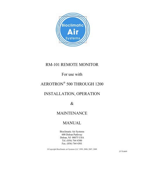
<strong>RM</strong>-<strong>101</strong> REMOTE MONITOR<br />
For use with<br />
AEROTRON ® 500 THROUGH 1200<br />
INSTALLATION, OPERATION<br />
&<br />
MAINTENANCE<br />
MANUAL<br />
<strong>Bioclimatic</strong> Air Systems<br />
600 Delran Parkway<br />
Delran, NJ 08075 USA<br />
Tel. (856) 764 4300<br />
Fax. (856) 764 4301<br />
©Copyright <strong>Bioclimatic</strong> air Systems LLC 1999, 2000, 2007, 2009<br />
257/Feb09
BIOCLIMATIC<br />
<strong>RM</strong>-<strong>101</strong> REMOTE MONITOR<br />
for use with<br />
AEROTRON ® 500 THROUGH 1200<br />
TABLE OF CONTENTS<br />
1 INTRODUCTION.....................................................................................................................................3<br />
1.1 Disclaimer...............................................................................................................................................3<br />
1.2 Recieving.................................................................................................................................................3<br />
1.3 Storage ....................................................................................................................................................4<br />
1.4 Warranty .................................................................................................................................................4<br />
2 PHYSICAL DESCRIPTION AND THEORY OF OPERATION ..........................................................5<br />
2.1 Principle of Operation............................................................................................................................5<br />
2.2 Front Panel Controls and Indicators ....................................................................................................7<br />
3 INSTALLATION......................................................................................................................................10<br />
3.1 Initial Setup.............................................................................................................................................10<br />
3.2 Electrical Connections ...........................................................................................................................10<br />
3.3 Special Instructions for Wiring of TB! And TB2 ...................................................................................11<br />
4 SYSTEM STARTUP.................................................................................................................................13<br />
5 OPERATION & MAINTENANCE OF UNIT ........................................................................................14<br />
5.1 General ...................................................................................................................................................14<br />
5.2 Calibration Procedure ...........................................................................................................................14<br />
5.3 Ionization Tubes .....................................................................................................................................16<br />
5.4 Troubleshooting Guide...........................................................................................................................17<br />
5.5 Troubleshooting Table ...........................................................................................................................18<br />
6 SPECIFICATIONS...................................................................................................................................19<br />
6.1 Electrical.................................................................................................................................................19<br />
6.2 Mechanical..............................................................................................................................................19<br />
7 APPENDIX A – Figures 1, 3, 4, 5, 6
<strong>RM</strong>-<strong>101</strong> – I, O, & M Manual<br />
Page 3<br />
1 INTRODUCTION<br />
1.1 Disclaimer<br />
These instructions are submitted with the implicit understanding that:<br />
1.1.1 This manual is to guide the user of <strong>Bioclimatic</strong> equipment in the proper<br />
installation, operation and maintenance procedures to insure maximum<br />
equipment life with efficient operation.<br />
1.1.2 The customer has assigned competent maintenance and operating personnel<br />
to the system described herein and will assume operational and maintenance<br />
responsibility upon start-up of the system.<br />
1.1.3 The customer will read and thoroughly examine the foregoing instructions<br />
and will notify the seller of any points not fully understood, points of conflict<br />
or error.<br />
1.1.4 The customer, in lieu of any notification to the contrary, has read and fully<br />
understands the operation of the System and is aware of the hazards of<br />
corrosion, abrasion and fire or explosion and shall take the necessary steps in<br />
the operation of equipment to control such hazards to the maximum extent<br />
possible.<br />
1.1.5 Start-up assistance or field engineering service provided by <strong>Bioclimatic</strong> shall<br />
in no way relieve the customer of responsibility for the proper operation of<br />
the System.<br />
IMPORTANT: Any modifications to the unit by unauthorized personnel will void<br />
ETL listing and factory warranty. The unit must be installed in accordance with the<br />
manufacturer’s instructions to preserve warranty and ETL label.<br />
1.2 Receiving<br />
Products leaving the <strong>Bioclimatic</strong> factory are inspected and in satisfactory operating<br />
condition. All equipment should be thoroughly inspected when received. Although all units<br />
are properly packaged, rough handling in transit can cause breakage. Any shortage or<br />
damage should be reported at once to the transportation company. Note the damage on the<br />
bill of lading before signing for the shipment. No equipment may be returned to<br />
<strong>Bioclimatic</strong> without written authorization. Returned equipment sent without<br />
authorization will be refused and returned to sender.
<strong>RM</strong>-<strong>101</strong> – I, O, & M Manual<br />
Page 4<br />
All products are shipped F.O.B. <strong>Bioclimatic</strong> warehouse. Responsibility for all equipment<br />
passes to the Buyer at the time equipment is loaded onto the carrier's truck.<br />
1.3 Storage<br />
If the <strong>RM</strong>-<strong>101</strong> is not installed upon delivery, it should be stored in a cool, dry, weather<br />
protected location. Do not stack any other equipment on top of the unit.<br />
Warranty<br />
THE SELLER WARRANTS THE EQUIPMENT AGAINST DEFECTIVE WORKMANSHIP<br />
AND MATERIAL FOR FIFTEEN (15) MONTHS FROM DATE OF FACTORY SHIPMENT<br />
OR ONE (1) YEAR FROM COMMISSIONING, WHICHEVER OCCURS FIRST. IN THE<br />
FULFILLMENT OF ITS WARRANTY, THE SOLE OBLIGATION OF SELLER SHALL BE TO<br />
REPAIR OR REPLACE, AT ITS OPTION, F.O.B. ITS FACTORY, ANY PART OR PARTS<br />
WHICH ARE RETURNED F.O.B. ITS FACTORY, SHIPPING CHARGES PREPAID, AND<br />
WHICH AFTER INSPECTION BY SELLER ARE FOUND TO BE DEFECTIVE. BUYER<br />
SHALL NOTIFY SELLER OF DEFECT IN WRITING, PROMPTLY UPON DISCOVERY AND<br />
WITHIN THE WARRANTY PERIOD. THIS WARRANTY DOES NOT COVER DEFECTS<br />
CAUSED BY CORROSION OR NO<strong>RM</strong>AL DETERIORATION; IT DOES NOT EXTEND TO<br />
CONSEQUENTIAL DAMAGE, LOSS OR DELAY ASSOCIATED WITH A WARRANTY<br />
DEFECT; AND IT DOES NOT COVER ANY COST OF LABOR, TRAVEL, OR OTHER<br />
EXPENSE ASSOCIATED WITH THE REPAIR OR REPLACEMENT OF DEFECTIVE PARTS.<br />
SELLER ASSUMES NO LIABILITY FOR PRODUCT LOSS OR OTHER CLAIMS<br />
WHATSOEVER ARISING OUT OF THE USE OR APPLICATION OF THE EQUIPMENT IN<br />
ANY OPERATIONS, WHETHER THE MACHINE IS USED ALONE OR IN CONJOINT USE<br />
WITH OTHER EQUIPMENT OR PROCESSES. NOTWITHSTANDING THE FOREGOING,<br />
SELLER'S WARRANTY OBLIGATIONS WITH RESPECT TO ANY ITEMS NOT<br />
MANUFACTURED BY SELLER SHALL NOT EXCEED THE OBLIGATIONS UNDERTAKEN<br />
BY THE MANUFACTURER THEREOF UNDER EXPRESS WARRANTY TO THE SELLER.<br />
THIS EXPRESS WARRANTY IS IN LIEU OF ALL OTHER WARRANTIES OF FITNESS OF<br />
THE MACHINE FOR ANY PARTICULAR PURPOSE.<br />
THERE ARE NO OTHER REPRESENTATIONS, WARRANTY OF CONDITION IN ANY<br />
RESPECTS EXPRESS OR IMPLIED, STATUTORY OR OTHERWISE IN CONTRACT OR<br />
TORT, OTHER THAN WHAT IS STATED ABOVE.<br />
THE SELLER SHALL NOT BE HELD LIABLE IN ANY WAY FOR CONSEQUENTIAL<br />
DAMAGES, HOWEVER CAUSED.<br />
THIS WARRANTY WILL NOT APPLY IF THE SELLER’S EQUIPMENT HAS BEEN<br />
DAMAGED DUE TO IMPROPER INSTALLATION, ALTERATION, ABUSE OR MISUSE,<br />
ACCIDENT, FIRE, FLOOD OR ACT OF GOD. FURTHER, THIS WARRANTY WILL NOT<br />
APPLY IF REPAIRS, REPLACEMENTS, OR ALTERATIONS ARE MADE BY OTHERS<br />
WITHOUT THE SELLER’S PRIOR WRITTEN AUTHORIZATION.<br />
IN THE EVENT THE STATE IN WHICH THE EQUIPMENT IS INSTALLED DOES NOT<br />
PE<strong>RM</strong>IT THE LIMITATION OR EXCLUSION OF IMPLIED WARRANTIES OR<br />
CONDITIONS UNDER GIVEN CIRCUMSTANCES, THE PROVISIONS OF THIS WRITTEN<br />
WARRANTY ARE IN ADDITION TO AND NOT A MODIFICATION OF THE STATUTORY<br />
WARRANTIES AND OTHER RIGHTS AND REMEDIES PROVIDED BY SUCH LAWS.
<strong>RM</strong>-<strong>101</strong> – I, O, & M Manual<br />
Page 5<br />
NOTE:<br />
“ANY MODIFICATION TO ORIGINAL EQUIPMENT BY ANY COMPANY OR PERSON<br />
OTHER THAN THE MANUFACTURER WILL SERVE TO CANCEL AND VOID ALL OF<br />
THE SELLER’S LIABILITY UNDER THE MANUFACTURER’S WARRANTY.<br />
ENCLOSURES CONTAINING ELECTRONIC COMPONENTS ARE NO<strong>RM</strong>ALLY SEALED<br />
BY THE MANUFACTURER TO PREVENT UNAUTHORIZED TAMPERING OR<br />
ADJUSTMENTS. ONLY AUTHORIZED SERVICE PROVIDES MAY BREAK SEALS TO<br />
COMPLETE CALIBRATION OR TO TROUBLE SHOOT THE UNIT. UNAUTHORIZED<br />
TAMPERING OR BREAKING SEALS WILL RELEASE THE SELLER FROM ANY<br />
FUTURE LIABILITY UNDER THE WARRANTY”.<br />
2 PHYSICAL DESCRIPTION AND THEORY OF OPERATION<br />
2.1 Principle of Operation<br />
2.1.1 <strong>RM</strong>-<strong>101</strong><br />
The <strong>RM</strong>-<strong>101</strong> Remote Monitor is an electronically controlled power regulator and<br />
visual status indicator designed to operate in conjunction with single or multiple bipolar<br />
ionization generators. The <strong>RM</strong>-<strong>101</strong> is used to simultaneously regulate the<br />
output and individually monitor the operating status of up to 12 power generators in<br />
a system.<br />
The <strong>RM</strong>-<strong>101</strong> Remote Monitor is an entirely self-contained unit designed for wall or<br />
surface mounting. Electronic circuitry and power regulation devices together with<br />
associated ionization level control and visual status indicators are all housed within<br />
an impact-resistant polycarbonate enclosure. A transparent acrylic hinged door<br />
covers front panel controls and indicators. This cover affords protection against<br />
accidental or unauthorized adjustment of the power control while affording<br />
unobstructed visual access to the status indicator lights.<br />
The <strong>RM</strong>-<strong>101</strong> has three operating ranges, "Low" (under), "Normal" and "High"<br />
(overload). Each range is adjusted within certain limits of ionization as set by the<br />
level control on the front panel. As the ionization control is advanced (turned up),<br />
ionization increases and the status indicators will switch in sequence from Low<br />
(Amber) to Normal (Green) to High (Red), thus providing a visual indication of<br />
output level. Since the level control is continuously variable, system operators are<br />
free to make level changes within each operating range depending upon<br />
environmental or other operating considerations.<br />
2.1.2 <strong>RM</strong>-<strong>101</strong> Power Connections & System Options (Figure 1)<br />
All primary power connections as well as output regulated load lines and other<br />
options are all available on front mounted terminal blocks located for convenient<br />
access behind a removable cover.
<strong>RM</strong>-<strong>101</strong> – I, O, & M Manual<br />
Page 6<br />
Terminal Block TB1 includes the following:<br />
a) Unregulated primary power input,<br />
b) Separate (switched 10 Amp) unregulated convenience power (115 VAC), and<br />
c) Three independently controlled regulated 5 Amp load lines.<br />
Terminal Block TB2 includes the following:<br />
a) Twelve (12) separate input terminals for ion generator fault sensing and visual<br />
status indication, and<br />
b) Terminal connections for system air flow differential or static pressure<br />
switch (filter alarm feature).<br />
c) Provisions for three-wire interconnection for external fault monitoring<br />
equipment or building management system.<br />
A comprehensive discussion of these and other features of the <strong>RM</strong>-<strong>101</strong> will be given<br />
under Section 3 (INSTALLATION) and under Section 5 (OPERATION &<br />
MAINTENANCE OF UNIT).<br />
2.1.3 Aerotron Bi-Polar Ionization Unit<br />
The Bi-polar ionization unit consists of a power generator and ionization tubes.<br />
The power generator produces line synchronized bi-polar ionization of an airstream<br />
whose flow is perpendicular to the axis of the tubes. Thus, depending upon the<br />
volume of air, its velocity, chemical and biological content, ionization is adjusted by<br />
means of local control to affect particle discharge density sufficient to produce the<br />
desired volumetric air purification. Externally, the power generator includes<br />
ionization tube sockets, spring contacts, fuse, fuse holder, indicator lamps and<br />
mounting plate.<br />
The ionization tube consists of two electrodes, a glass tube and a plastic base with a<br />
male threaded connector. The external electrode is crimped around the glass tube by<br />
the manufacturer, and under no circumstances should it be removed from the tube.<br />
The glass tubing material is fragile and should be handled with care. Cracked or<br />
damaged glass will cause a system malfunction and require tube replacement.<br />
NOTE: Ozone is a by-product of any ionization process. When installed and<br />
operated in accordance with manufacturers instructions, the <strong>Bioclimatic</strong><br />
System will not generate ozone in excess of the safety standards specified by<br />
OSHA and FDA. Under normal operating conditions, there will not be<br />
measurable levels of ozone.
<strong>RM</strong>-<strong>101</strong> – I, O, & M Manual<br />
Page 7<br />
2.2 Front Panel Controls and Indicators<br />
Figure 2<br />
Front Panel Controls & Indicators<br />
Functional Description<br />
Turns system on & off. Rotating control adjusts the ionization output of all generators<br />
simultaneously and equally.<br />
Lights up when all generators are operating in “Low” status.<br />
Lights up when all generators are operating in “Normal” status.<br />
Lights up when all generators are operating in “High” status.<br />
Selects ionization generator to be monitored.<br />
Main system fuse. Size depends upon number of ionization generators. See TABLE 2, Section<br />
2.2.4 (System Fuse).<br />
Momentary switch to test operation of Dirty Filter Indicator, lamp .<br />
Power Indicator lamp turns on when system is in operation.<br />
Dirty Filter Indicator turns on automatically when system air filters become contaminated. In<br />
normal operation (clean filters) this lamp is extinguished except when operated by Filter Test<br />
Switch, lamp .<br />
Test Jack for monitoring individual ionization generator as selected by Generator Selector<br />
Switch, lamp .
<strong>RM</strong>-<strong>101</strong> – I, O, & M Manual<br />
Page 8<br />
2.2.1 On/Off Ionization Level Control <br />
Turns system ON and OFF. Rotating (c/w max) this control sets system ionization<br />
level to desired range as indicated by the ionization status indicators, , & .<br />
2.2.2 Ionization Status Lamps , & <br />
The three ionization status indicator lamps (LED's) provide a visual reference of how<br />
system generators are operating at the time of observation. These LED indicators<br />
must be observed in conjunction with the 12-position generator selector switch, .<br />
The three status lamps convey information on the status of only one generator at a<br />
time as selected by . This individual selective monitoring in the <strong>RM</strong>-<strong>101</strong> differs<br />
from the multi-channel, non-switched operation inherent in the <strong>RM</strong>-600(A) & <strong>RM</strong>-<br />
1200(A) Remote Monitors, where individual generators are monitored<br />
simultaneously with a bank of three status lamps available for each generator.<br />
The three LED lamps marked Low (Amber), Normal (Green), and High (Red)<br />
indicate three operating conditions. All generators in the system operate in response<br />
to the position set by the ionization level control. Each setting is calibrated at the<br />
factory within specified limits as shown in TABLE 1.<br />
The Normal (Green) range is recommended for all standard ionization applications.<br />
Both the Low (Amber) and High (Red) indices represent abnormal operating<br />
conditions, hence they are referred to as "faults".<br />
TABLE 1<br />
Indicator Ionization<br />
Range Light Tube Potential Operating<br />
Indication Color VAC(rms) 60Hz Condition<br />
Low (fault) Amber 1250 to 1500 Negligible ionization<br />
Norm Green 1500 to 2400 Normal ionization<br />
High (fault) Red 2400 to 2500 High voltage, Ozone potential<br />
Note: Additional information concerning the operation of the 12-position generator<br />
selector switch and the interpretation of the amber, green & red indicator lights is<br />
found in Section 5.4 (Troubleshooting Guide).
<strong>RM</strong>-<strong>101</strong> – I, O, & M Manual<br />
Page 9<br />
2.2.3 Generator Selector Switch (Fault and Status Indication)<br />
As noted above, the generator selector switch may be rotated to select<br />
individual inputs from 12 separate generators.<br />
The data from each is internally processed by the <strong>RM</strong>-<strong>101</strong> and activates the<br />
appropriate status lamp for the generator when selected. Hence, by setting the<br />
switch to position No. 4, for example, the operating status of generator No. 4 is<br />
observed by the illumination of the appropriate status LED. If the switch is<br />
rotated starting at position No. 1 through position No. 4 (assuming a four -<br />
generator system), each time the switch is advanced numerically, the<br />
corresponding generator is monitored.<br />
2.2.4 System Fuse <br />
This is main system fuse is located on the front panel. It protects the <strong>RM</strong>-<strong>101</strong> power<br />
control circuitry and the electric service feeding all generators in the system. DO<br />
NOT substitute or jump this fuse. Replace only with the exact type provided by<br />
<strong>Bioclimatic</strong>.<br />
NOTE: Use AGC type fast acting fuse only. FLA ratings based on average current estimates using<br />
“F” type Ionization tubes.<br />
2.2.5 Filter Test Switch <br />
This is a momentary push-button switch that, when depressed, activates and turns on<br />
the dirty filter indicator lamp to simulate a contaminated filter condition. It also<br />
tests the integrity of the circuit connected to the air differential pressure switch.<br />
2.2.6 Power Indicator <br />
This is a monitor lamp, which monitors power to the system. When the On/Off<br />
Control switch is turned on, the lamp comes on. When this switch is turned off,<br />
the lamp goes out.<br />
2.2.7 Dirty Filter Indicator <br />
This indicator lamp works in conjunction with the air differential pressure switch<br />
located in the air plenum across the air entering and air leaving side of the filter.<br />
As the filter accumulates more and more particles from the air stream, the static<br />
pressure across the filter gradually increases until the threshold sensitivity of the<br />
switch is reached. At this point, it activates the switch turning ON the indicator<br />
lamp.<br />
2.2.8 Test Jack
<strong>RM</strong>-<strong>101</strong> – I, O, & M Manual<br />
Page 10<br />
The test jack provides a convenient way to measure the presence of ionization high<br />
voltage on each generator selected by the generator selector switch . Risk of shock<br />
and personal injury is eliminated during measurement because the test jack carries a<br />
proportionally derived but greatly reduced potential (less than 3.0 Volts) compared to<br />
the actual ionization potential shown in Figure 5.<br />
Figure 5 included in Section 5.4 (Troubleshooting Guide) also shows the relationship<br />
between ionization voltage and corresponding test jack voltage and the status of the<br />
three range indicator status lamps.<br />
3 INSTALLATION (Figure 1 & 3)<br />
3.1 Initial Setup<br />
3.1.1 Aerotron Bi-Polar Ionization Units<br />
Unregulated Aerotron units are designed for installation totally within the plenum of<br />
an air handling unit.<br />
Install ionization tubes as follows:<br />
3.1.1.1 Screw tubes into socket by holding the leaf spring clear of tube<br />
surface.<br />
3.1.1.2 Turn tube into socket by the plastic base.<br />
3.1.1.3 After tube contacts base, tighten an additional 1/8 to ¼ turn. Do not<br />
use hand tools to tighten tubes, as they will damage the glass tubes.<br />
3.1.1.4 Ensure leaf spring is in contact with outer mesh.<br />
3.1.1.5 Close access door.<br />
NOTE: The ionization tubes are fragile – Handle With Care.<br />
3.1.2 <strong>RM</strong>-<strong>101</strong> Unit<br />
WARNING!! The <strong>RM</strong>-<strong>101</strong> is designed for interior surface wall mounting only. Never<br />
install the <strong>RM</strong>-<strong>101</strong> outdoors or in any location not covered by Section 6<br />
(SPECIFICATIONS) of this manual.<br />
Choose a suitable location not more than 50 feet from the operating generators.<br />
Greater distances will require special interconnect wiring. Mount the unit eye level<br />
on a wall or other vertical structure and install conduit as required.<br />
3.2 Electrical Connections
<strong>RM</strong>-<strong>101</strong> – I, O, & M Manual<br />
Page 11<br />
Remove the access cover from lower part of <strong>RM</strong>-<strong>101</strong> exposing the main termination<br />
blocks marked TB1 and TB2. All electrical connections to and from the <strong>RM</strong>-<strong>101</strong> are<br />
made at TB1 and TB2. Refer to Figure 3 for a detail system wiring diagram, and to<br />
Figure 1 showing an exploded view of both TB1 and TB2.<br />
WARNING!! Do not attempt to connect the <strong>RM</strong>-<strong>101</strong> to electrical service unless you<br />
are qualified to do so. Electrical connections must be performed by a licensed<br />
electrician or other qualified personnel.<br />
Multiple bi-polar ionization generators (up to 12) may be connected to a single <strong>RM</strong>-<br />
<strong>101</strong>. Figure 3 shows a typical <strong>RM</strong>-<strong>101</strong> controlling twelve separate Bi-Polar<br />
ionization generators. The regulated power wiring fed to the generators must<br />
conform to applicable codes specified by NFPA/NEC, (wiring in ducts, plenums and<br />
other air handling spaces) when the generator units are installed inside a Side Access<br />
Housing or other enclosed air handling unit plenum.<br />
TB1 and TB2 Connections<br />
The connection terminals on TB1 and TB2 are designed to accommodate up to 14-<br />
gauge stranded electrical wire. Primary connections to electric service are made at<br />
TB1, terminals L, N & G. These terminals correspond respectively to Line (L),<br />
Neutral (N) and Ground (G) in Standard 115V, 1φ, 3W grounding systems and Line<br />
1 (L1), Line 2 (L2) and around (G) in 230V, 1φ, 3W ground systems.<br />
CAUTION: DO NOT attempt to connect the <strong>RM</strong>-<strong>101</strong> across multi-phase 3 or 4 wire<br />
circuits or across any electrical service in which pole to pole voltage exceeds 240 Volts<br />
rms.<br />
Carefully strip insulation 3/8-inch from ends. Twist strands evenly and insert wire<br />
into the access hole opened by pressing down on the slotted tab using a small<br />
screwdriver. Releasing the tab will clamp wire securely in place. Terminals 7, 8 & 9<br />
on TB1 marked L, N & G are the system "load" terminals and follow the same<br />
configuration with respect to Line/Neutral/Ground assignments, as do the primary<br />
terminals. Terminals marked "G" are common ground and should be externally tied<br />
to common system ground. Ground faults must not exist between these two ground<br />
terminals.<br />
Run a separate line (20 AWG stranded wire) from each Aerotron generator terminal<br />
to the corresponding terminal of TB2; e.g. generator #1 connected to TB2-1,<br />
generator #2 to TB2-2, etc. The numbered terminals 1-12 on TB2 are for fault<br />
sensing only. DO NOT connect AC power wiring to TB2-1 through 12.<br />
3.3 Special Instructions for Wiring of TB1 and TB2
<strong>RM</strong>-<strong>101</strong> – I, O, & M Manual<br />
Page 12<br />
As described under Section 2.1.2 (<strong>RM</strong>-<strong>101</strong> Power Connections & System Options)<br />
TB1 and TB2 afford several options including multiple regulated (5 Amp) load<br />
lines; separate switched (10 Amp) unregulated convenience outlet plus provisions for<br />
external fault status indication and differential pressure connections for filter alarm.<br />
Note on Figure 1, the primary power is connected to TB1-1-3 and the regulated<br />
power output lines to the ionization generators are marked output 1 (terminals TB1-<br />
7-9), output 2 (terminals TB1-10-12) and output 3 (terminals TB1-13-15).<br />
While all three outputs are essentially in parallel and all controlled by the setting of<br />
the level control on the front panel, it is important to distinguish between each output<br />
in terms of total load current and the number of generators and their types in the<br />
system. It is important for proper system operation that load currents be equally<br />
distributed between the output lines in use. DO NOT integrate connections of<br />
dissimilar generators on any single output port. It is further recommended that no<br />
less than two, or more than four generators be connected to any one output terminal.<br />
TABLE 2 below shows the proper way to connect the generators to provide the<br />
proper load distribution for each regulated output port.<br />
Output Port Configuration<br />
TABLE 2<br />
Total<br />
Number of Output 1 Output 2 Output 3<br />
Generators Generator Generator Generator<br />
in System Number Number Number<br />
2 1-2<br />
3 1-2-3<br />
4 1-2-3-4<br />
6 1-2-3 4-5-6<br />
8 1-2-3-4 5-6-7-8<br />
9 1-2-3 4-5-6 7-8-9<br />
12 1-2-3-4 5-6-7-8 9-10-11-12<br />
The operation of the system is not affected by attaching any convenience device or<br />
other electric load to the switched line (terminals 4-5-6 on TB1) provided the load<br />
does not exceed 1.0KVA.<br />
Connections to terminals 1 through 12 on TB2 have already been discussed under<br />
Section 2.1.2 (<strong>RM</strong>-<strong>101</strong> Power Connections & System Options) and illustrated in<br />
Figure 1. Terminals 13-15 of TB2 provide direct connection to the pressure switch.
<strong>RM</strong>-<strong>101</strong> – I, O, & M Manual<br />
Page 13<br />
4 SYSTEM STARTUP<br />
Line voltage appears across terminals 13 & 14. These terminals are connected in<br />
series with the normally open contacts on the pressure switch. Terminal 15 is an<br />
auxiliary ground connection and may be used for purposes of grounding the metal<br />
case of the switch if required.<br />
Terminals 16-18 of TB2 are provided for interconnection to an external monitor or<br />
building management system. When the system is in the normal operating mode as<br />
indicated by the green status lamp on the front panel, terminals 16 & 17 are “open”<br />
and remain so for each generator selected by the generator selector switch, provided<br />
all generators are operating normally. Should one or more generators in the system<br />
fail, the defective generator will quickly be identified by the corresponding switch<br />
position and the status indication lamp; either High (Red) or Low (Amber). Should<br />
such a failure be detected, the corresponding status indication will provide a visual<br />
indication of the nature of the fault.<br />
When such faults are detected and displayed, the internal control fault relay will<br />
operate and provide a continuity path between terminals 16 & 17 (See Figure 4 on<br />
TB2).<br />
Terminal 18 on TB2 is a system ground connection to be used for grounding the<br />
shielded 2- wire cable connecting the external monitoring system to terminals 16 &<br />
17 on TB2. Normally, shielded cable is not required for cable runs under 50 feet.<br />
CAUTION!!! DO NOT energize the system without installing ionization tubes.<br />
After the power connections and generator sense lines have been secured at TB1 and all<br />
generators in the system have been connected as illustrated in Figure 3, the system may be<br />
turned on.<br />
Be sure that the generator status selector switch is set to position #1. Slowly, advance the<br />
gain control clockwise until the Green ionization status lamp illuminates. Check the range<br />
of this control and observe the point on the circular scale where the light switches to Low<br />
(Amber) and High (Red). These two switch points should correspond to dial settings of<br />
approximately 9 o'clock and 3 o'clock, respectively.<br />
Next, verify that all other generators in the system operate similarly. Switch generator<br />
selector to position #2 then #3, etc..., and verify operation as explained above for generator<br />
1.<br />
Finally, the gain control can be set to any position, within any of the "Green" ranges<br />
consistent with environmental requirements. The power regulator circuit in the <strong>RM</strong>-<strong>101</strong> will<br />
maintain correct operating conditions for all system generators. It is suggested that periodic
<strong>RM</strong>-<strong>101</strong> – I, O, & M Manual<br />
Page 14<br />
inspection be made of each generator to determine that it is functioning normally within the<br />
established Green operating range. This is accomplished by simply rotating the generator<br />
selector switch and observing the LED status indicators. All generators, when functioning<br />
normally, will display identical range indication regardless of the power control setting.<br />
5 OPERATION & MAINTENANCE OF UNIT<br />
5.1 General<br />
Should it become necessary to repair or replace the printed circuit board or component<br />
within the <strong>RM</strong>-<strong>101</strong> enclosure, recalibration of the unit is required. Erratic operation of the<br />
status indicator lights for all generators throughout the three ranges is an indication of failure<br />
of the ionization unit.<br />
If this condition exists for only one generator and the remaining generators operate normally,<br />
it is highly probable that one generator is defective and the <strong>RM</strong>-<strong>101</strong> needs no recalibration.<br />
Figure 4 shows an outline drawing of the <strong>RM</strong>-<strong>101</strong> printed circuit board. There are four (4)<br />
miniature trim pots located on the lower left hand portion of the circuit board. These are:<br />
R7 - Amber/Green Set<br />
R9 - Green/Red Set<br />
R28 - Low Limit Reg<br />
R26 - High Limit Reg<br />
Note: R7 and R9 adjust the keying relays that switch the indicator LED's. R28 and R26 set<br />
the high and low voltage limits for the power regulator. The two functions while separate in<br />
their operation, are interactive in their initial adjustments. R-28 & R-26 must be adjusted<br />
before R7 and R9.<br />
5.2 Calibration Procedure (Figure 4)<br />
CAUTION ! ! ! Hazardous voltages are exposed during this procedure. Extreme<br />
caution must be exercised. Work should be performed by or under supervision of a<br />
licensed electrician or other qualified personnel.<br />
5.2.1 Complete the installation of all equipment and secure all external wiring<br />
connections between all Ionization units and the <strong>RM</strong>-<strong>101</strong> as shown in Figure<br />
3. DO NOT energize the system at this time.<br />
5.2.2 Remove any one tube from its socket and insert the positive end of a high<br />
voltage insulated test probe directly into the threaded center jack on the tube<br />
socket. Connect the negative lead to the associated stainless steel ground<br />
spring. The opposite end of the test probe should be connected to an AC<br />
voltmeter with a rating of 5.0 KV peak. Alternatively, a high-voltage<br />
multiplier probe, similar to Fluke, <strong>Model</strong> 80K-6 may be used in conjunction
<strong>RM</strong>-<strong>101</strong> – I, O, & M Manual<br />
Page 15<br />
with a normal range AC voltmeter. In either case, observe proper safety<br />
precautions.<br />
5.2.3 Open the front cover on the <strong>RM</strong>-<strong>101</strong> and remove the face plate and front<br />
panel assembly. The electronic component circuit board is now exposed.<br />
5.2.4 Using a small blade screwdriver, position R-28 and R-26 to mid-range.<br />
5.2.5 Energize the system now by clicking on the ionization level control knob.<br />
Do not advance control, leave it turned fully counter-clockwise.<br />
5.2.6 With the system energized and the ionization level control set to minimum,<br />
carefully adjust R-28 until a reading of 1250 Volts AC is obtained on the<br />
meter. This is the minimum operating voltage for all system generators.<br />
5.2.7 Now, turn the ionization level control wide open to its maximum clockwise<br />
position and observe the reading on the AC voltmeter.<br />
5.2.8 Adjust R-26 until a reading of 2500 Volts AC is obtained. This is the<br />
maximum operating voltage for all system generators.<br />
5.2.9 Check the low limit (1250 VAC) by returning the ionization level control to<br />
its minimum setting. Some additional adjustment may now be necessary.<br />
Re-adjust R-28 if necessary and repeat steps 7, 8, & 9 until the desired results<br />
are obtained. R-28 and R-26 are properly set when the full excursion of<br />
the ionization level control from minimum to maximum produces a<br />
range of 1250 to 2500 ± 25 VAC.<br />
5.2.10 Using a small blade screwdriver, next, set the position of both R7 and R9 to<br />
mid-range. Note, R7 and R9 are 10-turn trim pots, so count off 5 turns when<br />
making this initial adjustment.<br />
5.2.11 Set the ionization level control to indicate a reading of 1500 VAC on the<br />
meter. This voltage corresponds to the fault threshold between "Low" and<br />
"Normal" ionization ranges as indicated by the respective front panel LED's.<br />
Adjust R7 until the LED switch point is found between Low (Amber) and<br />
Normal (Green). This switch point will occur alternately within a 1 or 2 turn<br />
range of R7. The proper setting for R7 is midway within this 1 or 2 turn<br />
range.<br />
5.2.12 Set the ionization level control to indicate a reading of 2400 VAC on the<br />
meter. This voltage corresponds to the fault threshold between "Normal" and<br />
"High" ionization as indicated by the respective front panel LED's. Adjust<br />
R9 until the LED switch point is found between Normal (Green) and High<br />
(Red). This switch point will occur alternately between a 1 or 2 turn range of<br />
R9. The proper setting for R9 is midway between this 1 or 2 turn range.
<strong>RM</strong>-<strong>101</strong> – I, O, & M Manual<br />
Page 16<br />
5.2.13 Now go back and recheck the switch point between Amber and Green,<br />
making sure that it occurs when the meter indicates 1500 ± 50 VAC. It may<br />
be necessary to read just as described in steps 10 through 13. R7 and R9 are<br />
correctly adjusted when switching occurs at the voltages given above<br />
and in TABLE 1, column 3.<br />
5.2.14 This completes all adjustments required to calibrate the <strong>RM</strong>-<strong>101</strong>. Turn the<br />
system off. Re-position the front panel and fasten all hardware. Close the<br />
cover, re-install unit, and connect all wiring to appropriate terminals on TB1<br />
and TB2. Re-attach the lower access cover.<br />
The calibration procedure, steps 1 - 14 outlined above are summarized in Figure 5, (Range &<br />
Status Calibration).<br />
5.3 Ionization Tubes<br />
The ionization tubes must be washed on a periodic basis to ensure operating<br />
efficiency. At minimum, they should be washed any time that the primary filter is<br />
serviced but in no case longer than one year. The tubes can be washed using the<br />
following procedure:<br />
IMPORTANT: Make sure all power to the unit is disconnected before performing this<br />
or any maintenance procedure.<br />
5.3.1 Remove the tubes from the unit by lifting the leaf spring from the surface of<br />
the tube and unscrew each tube.<br />
5.3.2 A solution of warm water and non-abrasive detergent can be used to clean<br />
the tubes.<br />
5.3.3 A soft nylon brush may be used to remove embedded material within the<br />
external electrode.<br />
NOTE: Do not attempt to remove the tube's outer electrode.<br />
5.3.4 Rinse with clean water after washing.<br />
5.3.5 Replace ionization tubes only after they are completely dry. Pay special<br />
attention to removing moisture from the polycarbonate base.<br />
5.3.6 Screw tube into socket by holding the leaf spring clear of tube surface. Turn<br />
tube into socket by the plastic base. After tube contacts base, tighten an<br />
additional 1/8 to 1/4 turn.<br />
NOTE: Do not use hand tools to tighten tubes, as they will damage the glass tubes.<br />
5.3.7 Make sure that the leaf spring is in contact with tube surface.<br />
REMEMBER: The tubes are fragile - Handle With Care.
<strong>RM</strong>-<strong>101</strong> – I, O, & M Manual<br />
Page 17<br />
5.4 Troubleshooting Guide<br />
Under normal operating conditions, assuming the adjustments described in Section 5<br />
(OPERATION & MAINTENANCE OF UNIT) have been made, all generators will respond<br />
uniformly to changes in position or setting of the power control located on the front panel of<br />
the <strong>RM</strong>-<strong>101</strong>. If the power control is set fully counter-clockwise, the Low (Amber) LED will<br />
light for each generator as selected by the channel selector switch. As the power control is<br />
advanced in a clockwise direction, the Normal (Green) LED will illuminate and the Amber<br />
light will extinguish. Additional advancement of the control will eventually cause the High<br />
(Red) LED to illuminate and Normal (Green) to extinguish.<br />
Periodic inspection of the system generators is recommended to determine proper operation.<br />
The following procedure is suggested.<br />
5.4.1 Open the lucite cover on <strong>RM</strong>-<strong>101</strong> and reduce the power control to minimum<br />
(fully CCW).<br />
5.4.2 Rotate generator selector switch (starting on position #1) clockwise in<br />
numerical order, stopping on each channel number assigned to a functioning<br />
ionization generator. For example, if your system uses four (4) ionization<br />
generators, you select channels 1, 2, 3 & 4.<br />
5.4.3 Pause on each channel long enough to check the operation of the LED<br />
indicators, as the power control is rotated through its 270 degree rotation<br />
from minimum setting to maximum setting.<br />
5.4.4 Selected channels should respond in a similar manner with LED's switching<br />
at approximately the same point for each channel as indicated in the<br />
following diagram:<br />
Diagram depicts the approximate<br />
position of Ionization Gain Control<br />
for proper range switching.<br />
Ionization Gain Control<br />
Note the above diagram indicates only the approximate position of the ionization gain<br />
control for various switch points and ranges. The diagram provides a qualitative check for<br />
determining uniform operation (relative performance) of each ionization generator in the<br />
system. Quantitative data may be obtained by following the procedure authorized in Section<br />
5.2, (Calibration Procedure).
<strong>RM</strong>-<strong>101</strong> – I, O, & M Manual<br />
Page 18<br />
If all generators, as selected by the <strong>RM</strong>-<strong>101</strong> channel selector switch on the front panel<br />
respond uniformly according to the above procedure, then all generators are assumed<br />
to be operating normally.<br />
The <strong>RM</strong>-<strong>101</strong> will detect and respond to a faulty ionization generator by showing a nonuniform<br />
LED indication for the faulty generator when that generator is chosen by the<br />
selector switch. For example, in a six-generator system, assuming a fuse is blown in<br />
generator No. 4, the Low (Amber) LED will illuminate throughout the entire range of the<br />
ionization gain control with the channel selector in position #4.<br />
Whereas, channels 1, 2, 3, 5 & 6 will all respond uniformly as described in Step 4 above.<br />
Thus, the "non-uniform" or non-conforming channel 4 generator is assumed to be defective.<br />
The <strong>RM</strong>-<strong>101</strong> can be useful in establishing preliminary fault conditions, as described above;<br />
however, it can not be relied upon to determine the exact nature of the fault, only that a fault<br />
exists and in a particular generator. This information however is sufficient to indicate the<br />
need for further troubleshooting. To help provide a more detailed guide for troubleshooting<br />
system problems, refer to the following table Section 5.5 (Troubleshooting), listing fault<br />
conditions, probable cause and corrective action. Do not hesitate to contact the factory for<br />
assistance. Figure 6 shows a complete electrical schematic diagram for the <strong>RM</strong>-<strong>101</strong>.<br />
5.5 Troubleshooting Table<br />
Fault Condition Probable Cause Corrective Action<br />
1. LED's Amber Gain control set too low Raise Level<br />
All Channels All generator fuses blown Replace<br />
2. LED's Red Gain control set too high Lower Level<br />
All Channels<br />
3. Single Channel Shorted ionization tube Replace<br />
LED Amber Problem with electronic Contact Factory<br />
circuit board<br />
4. Single Channel Shorted ionization tube Replace<br />
LED Red Problem with electronic Contact Factory<br />
circuit board<br />
5. Flickering LED's Defective ionization tube Replace
<strong>RM</strong>-<strong>101</strong> – I, O, & M Manual<br />
Page 19<br />
Red, Green, Amber in system<br />
One or More Power line interruptions Check power line<br />
Channels<br />
voltage 120 VAC<br />
6. System Operating Defective PC Board Contact Factory<br />
Normally, All Front<br />
Panel LED's Out<br />
Notice:<br />
Corrective action must be performed by qualified personnel only. Refer to<br />
manufacturer's recommended replacement procedures for ionization tubes.<br />
WARNING: DO NOT ATTEMPT TO REPLACE ANYTHING WHILE POWER TO THE<br />
SYSTEM IS ON. DISCONNECT ALL POWER BEFORE SERVICING ANY<br />
UNIT.<br />
6 SPECIFICATIONS<br />
6.1 Electrical<br />
Power Requirement:<br />
115/230 volts AC, 1 phase 50/60 Hz<br />
Power Consumption:<br />
no load - 5.0 watts max.<br />
full load - 800 watts max.<br />
Max. Number Generators: Twelve (12)<br />
Voltage Regulator Range:<br />
75 to 115/160 to 230 volts AC<br />
High Voltage Range:<br />
1100 VAC to 2700 VAC<br />
Ionization Tube Range Voltages: Low 1250 to 1500 VAC Fault<br />
Norm 1500 to 2400 VAC<br />
High 2400 to 2500 VAC Fault<br />
Max. Operating Temperature: +80° C<br />
Sensing Voltage:<br />
1.3 to 3.3 volts AC<br />
Indicators:<br />
Hi-intensity LED's<br />
Power Regulator:<br />
Gate controlled triac<br />
6.2 Mechanical
<strong>RM</strong>-<strong>101</strong> – I, O, & M Manual<br />
Page 20<br />
Height:<br />
Width:<br />
Depth:<br />
Weight:<br />
Mounting:<br />
Environment:<br />
8.43 inches, 214 mm<br />
10.12 inches, 257 mm<br />
5.04 inches, 128 mm<br />
4.0 lbs., 1.8 Kg<br />
3 pt. (flat surface or walls)<br />
Indoor only