E1YM400VS10 Technical data
E1YM400VS10 Technical data
E1YM400VS10 Technical data

Create successful ePaper yourself
Turn your PDF publications into a flip-book with our unique Google optimized e-Paper software.
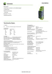
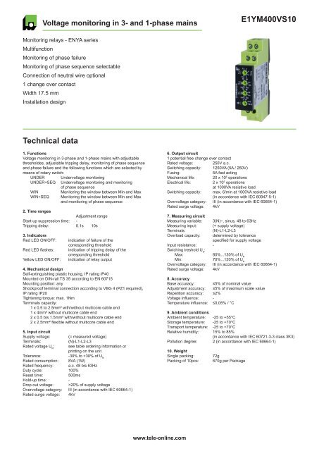
Voltage monitoring in 3- and 1-phase mains<br />
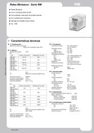
<strong>E1YM400VS10</strong><br />
Monitoring relays - ENYA series<br />
Multifunction<br />
Monitoring of phase failure<br />
Monitoring of phase sequence selectable<br />
Connection of neutral wire optional<br />
1 change over contact<br />
Width 17.5 mm<br />
Installation design<br />
<strong>Technical</strong> <strong>data</strong><br />
1. Functions<br />
Voltage monitoring in 3-phase and 1-phase mains with adjustable<br />
thresholdes, adjustable tripping delay, monitoring of phase sequence<br />
and phase failure and the following functions which are selected by<br />
means of rotary switch:<br />
UNDER Undervoltage monitoring<br />
UNDER+SEQ Undervoltage monitoring and monitoring<br />
of phase sequence<br />
WIN<br />
WIN+SEQ<br />
Monitoring the window between Min and Max<br />
Monitoring the window between Min and Max<br />
and monitoring of phase sequence<br />
2. Time ranges<br />
Adjustment range<br />
Start-up suppression time: -<br />
Tripping delay: 0.1s 10s<br />
3. Indicators<br />
Red LED ON/OFF:<br />
Red LED flashes:<br />
Yellow LED ON/OFF:<br />
indication of failure of the<br />
corresponding threshold<br />
indication of tripping delay of the<br />
orresponding threshold<br />
indication of relay output<br />
4. Mechanical design<br />
Self-extinguishing plastic housing, IP rating IP40<br />
Mounted on DIN-rail TS 35 according to EN 60715<br />
Mounting position: any<br />
Shockproof terminal connection according to VBG 4 (PZ1 required),<br />
IP rating IP20<br />
Tightening torque: max. 1Nm<br />
Terminals capacity:<br />
1 x 0.5 to 2.5mm² with/without multicore cable end<br />
1 x 4mm² without multicore cable end<br />
2 x 0.5 bis 1.5mm² with/without multicore cable end<br />
2 x 2.5mm² flexible without multicore cable end<br />
5. Input circuit<br />
Supply voltage: (= measured voltage)<br />
Terminals:<br />
(N)-L1-L2-L3<br />
Rated voltage U N<br />
: see table ordering information or<br />
printing on the unit<br />
Tolerance:<br />
-30% to +30% of U N<br />
Rated consumption: 8VA (1W)<br />
Rated frequency: a.c. 48 bis 63Hz<br />
Duty cycle: 100%<br />
Reset time:<br />
500ms<br />
Hold-up time: -<br />
Drop out voltage: >20% of supply voltage<br />
Overvoltage category: III (in accordance with IEC 60664-1)<br />
Rated surge voltage: 4kV<br />
6. Output circuit<br />
1 potential free change over contact<br />
Rated voltage: 250V a.c.<br />
Switching capacity: 1250VA (5A / 250V)<br />
Fusing:<br />
5A fast acting<br />
Mechanical life: 20 x 10 6 operations<br />
Electrical life:<br />
2 x 10 5 operations<br />
at 1000VA resistive load<br />
Switching capacity:<br />
max. 6/min at 1000VA resistive load<br />
(in accordance with IEC 60947-5-1)<br />
Overvoltage category: III (in accordance with IEC 60664-1)<br />
Rated surge voltage: 4kV<br />
7. Measuring circuit<br />
Measuring variable: 3(N)~, sinus, 48 to 63Hz<br />
Measuring input: (= supply voltage)<br />
Terminals:<br />
(N)-L1-L2-L3<br />
Overload capacity: determined by tolerance<br />
specified for supply voltage<br />
Input resistance: -<br />
Swiching treshold U S<br />
:<br />
Max:<br />
80%...130% of U N<br />
Min:<br />
70%...120% of U N<br />
Overvoltage category: III (in accordance with IEC 60664-1)<br />
Rated surge voltage: 4kV<br />
8. Accuracy<br />
Base accuracy: ≤5% of nominal value<br />
Adjustment accuracy: ≤5% of maximum scale value<br />
Repetition accuracy: ≤2%<br />
Voltage influence: -<br />
Temperature influence: ≤0,05% / °C<br />
9. Ambient conditions<br />
Ambient temperature: -25 to +55°C<br />
Storage temperature: -25 to +70°C<br />
Transport temperature: -25 to +70°C<br />
Relative humidity: 15% to 85%<br />
(in accordance with IEC 60721-3-3 class 3K3)<br />
Pollution degree: 2 (in accordance with IEC 60664-1)<br />
10. Weight<br />
Single packing:<br />
Packing of 10pcs:<br />
72g<br />
670g per Package<br />
www.tele-online.com
<strong>E1YM400VS10</strong><br />
Functions<br />
For all functions the LED‘s Min and Max are flashing alternating (the<br />
relay is fallen off), when the minimum value for the measured voltage<br />
was chosen to be greater than the maximum value.<br />
If a failure already exists when the device is activated, the output relay<br />
remains in off-position and the LED for the corresponding threshold is<br />
illuminated.<br />
The device includes seperately every phase voltage (L-N) and monitors<br />
it according to the selected function (UNDER or WINDOW).<br />
Undervoltage monitoring (UNDER, UNDER+SEQ)<br />
When the measured voltage (one of the phase voltages) falls below the<br />
value adjusted at the Min-regulator, the set interval of the tripping delay<br />
(Delay) begins (red LED Min flashes). After the interval has expired<br />
(red LED Min illuminated), the output relay R switches into off-position<br />
(yellow LED not illuminated). The output relay R switches into onposition<br />
again (yellow LED illuminated), when the measured voltage (all<br />
phase voltages) exceeds the value adjusted at the Max-regulator.<br />
Phase sequence monitoring (SEQ)<br />
Phase sequence monitoring is selectable for all functions.<br />
In single phase circuit, the phase sequence monitoring must be<br />
disconnected.<br />
If a change in phase sequence is detected (red LED SEQ illuminated),<br />
the output relay R switches into off-position after the set interval of<br />
tripping delay (Delay) has expired (yellow LED not illuminated).<br />
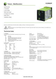
LED U<br />
LED Seq<br />
Delay<br />
Neutral wire break<br />
The device monitors every phase (L1, L2 and L3) against the neutral<br />
wire N.<br />
A shift of neutral point occurs by an asymmetrical phase load if the<br />
neutral wire breaks in the power line. If one of the phase voltages<br />
exceeds the value adjusted at the trip point, the set interval of tripping<br />
delay (Delay) begins (red LED Min or Max flashes). After the interval has<br />
expired (red LED Min or Max illuminated), the output relay switches into<br />
off-position (yellow LED not illuminated).<br />
Windowfunction (WIN, WIN+SEQ)<br />
The output relay R switches into on-position (yellow LED illuminated),<br />
when the measured voltage (all phase voltages) exceeds the value<br />
adjusted at the Min-regulator. When the measured voltage (one of the<br />
phase voltages) exceeds the value adjusted at the Max-regulator, the<br />
set interval of tripping delay (Delay) begins (red LED Max flashes).<br />
After the interval has expired (red LED Max illuminated) the output relay<br />
R switches into off-position (yellow LED not illuminated). The output<br />
relay switches into on-position again (yellow LED illuminated) when the<br />
measured voltage falls below the value adjusted at the Max-regulator<br />
(red LED Max not illuminated). When the measured voltage (one of the<br />
phase voltage) falls below the value adjusted at the Min-regulator, the<br />
set interval of tripping delay (Delay) begins again (red LED Min flashes).<br />
After the interval has expired (red LED Min illuminated), the output relay<br />
R switches into off-positon (yellow LED not illuminated).<br />
www.tele-online.com
<strong>E1YM400VS10</strong><br />
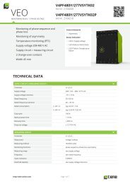
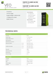
Connections<br />
Dimensions<br />
3N~<br />
L1<br />
L2<br />
L3<br />
N<br />
N<br />
L1<br />
L3<br />
L2<br />
45mm<br />
87mm<br />
15<br />
R<br />
16 18<br />
15<br />
16 18<br />
5mm<br />
44mm<br />
60mm<br />
17,5mm<br />
1~<br />
L<br />
N<br />
N<br />
L1<br />
L3<br />
L2<br />
15<br />
R<br />
16 18<br />
15<br />
16 18<br />
Ordering information<br />
Type Rated voltage U N<br />
Swiching treshold U S<br />
: Part. No.<br />
<strong>E1YM400VS10</strong> 3(N)~400/230V Max: 80%...130% of U N<br />
Min: 70%...120% of U N<br />
1340405<br />
RELEASE 2012/05<br />
Subject to alterations and errors<br />
www.tele-online.com