ESR-9753 - EnGenius Technologies
ESR-9753 - EnGenius Technologies
ESR-9753 - EnGenius Technologies

You also want an ePaper? Increase the reach of your titles
YUMPU automatically turns print PDFs into web optimized ePapers that Google loves.
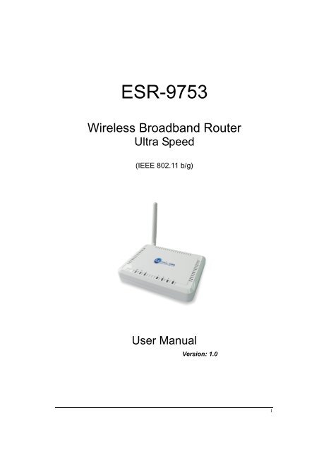
<strong>ESR</strong>-<strong>9753</strong><br />
Wireless Broadband Router<br />
Ultra Speed<br />
(IEEE 802.11 b/g)<br />
User Manual<br />
Version: 1.0<br />
1
TABLE OF CONTENTS<br />
1 INTRODUCTION ........................................................................................................................4<br />
2 KEY FEATURES..........................................................................................................................5<br />
3 PACKAGE CONTENTS..............................................................................................................6<br />
4 PRODUCT LAYOUT ...................................................................................................................7<br />
5 NETWORK + SYSTEM REQUIREMENTS.............................................................................9<br />
6 <strong>ESR</strong>-<strong>9753</strong> PLACEMENT.............................................................................................................9<br />
7 SETUP LAN, WAN .....................................................................................................................10<br />
8 PC NETWORK ADAPTER SETUP (WINDOWS XP) ............................................................11<br />
9 BRING UP <strong>ESR</strong>-<strong>9753</strong> .................................................................................................................13<br />
10 SMART WIZARD ......................................................................................................................13<br />
11 INITIAL SETUP <strong>ESR</strong>-<strong>9753</strong> .......................................................................................................22<br />
12 AP ROUTER MODE......................................................................................................................24<br />
13 REPEATER MODE .......................................................................................................................77<br />
APPENDIX A – FCC INTERFERENCE STATEMENT..................................................................93<br />
APPENDIX B – IC INTERFERENCE STATEMENT .....................................................................94<br />
2
Revision History<br />
Version Date Notes<br />
1.0 November 18, 2008 Modified from existing UM.<br />
3
1 Introduction<br />
Congratulations on your purchase of <strong>ESR</strong>-<strong>9753</strong> Wireless Network Broadband<br />
Router. <strong>ESR</strong>-<strong>9753</strong> is compatible with 802.11g & 802.11b gadgets. <strong>ESR</strong>-<strong>9753</strong> is<br />
not only a Wireless Access Point, but also doubles as a 4-port full-duplex Switch<br />
that connects your wired-Ethernet devices together at incredible speeds.<br />
At 150Mbps wireless transmission rate, Access Point built into the Router uses<br />
advanced MIMO (Multi-Input, Multi-Output) technology to transmit multiple<br />
steams of data in a single wireless channel giving you seamless access to<br />
multimedia content. Robust RF signal travels farther, eliminates dead spots and<br />
extends network range. For data protection and privacy, <strong>ESR</strong>-<strong>9753</strong> encodes all<br />
wireless transmissions with WEP, WPA, and WPA2 encryption.<br />
With inbuilt DHCP Server & powerful SPI firewall <strong>ESR</strong>-<strong>9753</strong> protects your<br />
computers against intruders and most known Internet attacks but provides safe<br />
VPN pass-through. With incredible speed and QoS function, <strong>ESR</strong>-<strong>9753</strong> is ideal<br />
for media-centric applications like streaming video, gaming, and VoIP telephony<br />
to run multiple media-intense data streams through the network at the same time,<br />
with no degradation in performance.<br />
4
2 Key Features<br />
Features Advantages<br />
Incredible Data Rate up to 150Mbps** Heavy data payloads such as<br />
MPEG video streaming<br />
IEEE 802.11b/g Compliant Fully Interoperable with IEEE<br />
Four 10/100 Mbps Fast Switch Ports<br />
(Auto-Crossover)<br />
Firewall supports, DMZ, MAC Filter, IP<br />
Filter, URL Filter, ICMP Blocking, SPI,<br />
Port Mapping, Port Forwarding, Port<br />
Trigger<br />
Support 802.1x Authenticator, 802.11i<br />
(WPA/WPA2, AES), VPN pass-through<br />
802.11b / IEEE 802.11g compliant<br />
devices with legacy protection<br />
Scalability, extend your network.<br />
Avoids the attacks of Hackers or<br />
Viruses from Internet<br />
Provide mutual authentication<br />
(Client and dynamic encryption<br />
keys to enhance security<br />
WDS (Wireless Distribution System) Make wireless AP and Bridge mode<br />
simultaneously as a wireless<br />
repeater<br />
** Theoretical wireless signal rate based on IEEE standard of 802.11a, b, g, n chipset used. Actual<br />
throughput may vary. Network conditions and environmental factors lower actual throughput rate.<br />
All specifications are subject to change without notice.<br />
5
3 Package Contents<br />
Open the package carefully, and make sure that none of the items listed below<br />
are missing. Do not discard the packing materials, in case of return; the unit must<br />
be shipped back in its original package.<br />
1. SOHO Router<br />
2. 100V~240V Power Adapter<br />
3. 2dBi 2.4GHz SMA Upgradable Antennas x 1 pcs<br />
4. Quick Install Guide<br />
5. CD (User’s Manual)<br />
6
4 Product Layout<br />
7
LED Description<br />
POWER<br />
WLAN<br />
LAN PORT ACTIVY<br />
100 Mbps<br />
Lights up when powered ON. Blinks on<br />
TEST/RESET<br />
Lights up in ORANGE when WLAN is<br />
enabled. Blinks on traffic<br />
Blinks on traffic for specific LAN PORT<br />
Lights up when 100 Mbps data rate<br />
enabled on that specific port<br />
ITEM Description<br />
Reset<br />
WPS<br />
DC IN<br />
LAN1 ~ 4<br />
INTERNET<br />
Click this button to restart the system, or<br />
Press this button and hold for 10 seconds<br />
to restart the system.<br />
Click this button to start WPS function.<br />
Power connector, connects to DC 12V<br />
Power Adapter<br />
Local Area Network (LAN) ports 1 to 4<br />
Wide Area Network(WAN) port<br />
8
5 Network + System Requirements<br />
To begin using the <strong>ESR</strong>-<strong>9753</strong>, make sure you meet the following as minimum<br />
requirements:<br />
� PC/Notebook.<br />
� Operating System – Microsoft Windows 98SE/ME/XP/2000/VISTA<br />
� 1 Free Ethernet port.<br />
� WiFi card/USB dongle (802.11b/g) – optional.<br />
� External xDSL (ADSL) or Cable modem with an Ethernet port (RJ-45).<br />
� PC with a Web-Browser (Internet Explorer, Safari, Firefox, Opera etc.)<br />
� Few Ethernet compatible CAT5 cables.<br />
6 <strong>ESR</strong>-<strong>9753</strong> Placement<br />
You can place <strong>ESR</strong>-<strong>9753</strong> on a desk or other flat surface, or you can mount it on a<br />
wall. For optimal performance, place your Wireless Broadband Router in the<br />
center of your office (or your home) in a location that is away from any potential<br />
source of interference, such as a metal wall or microwave oven. This location<br />
must be close to a power connection and your ADSL/Cable modem. If the<br />
antennas are not positioned correctly, performance loss can occur.<br />
9
7 Setup LAN, WAN<br />
LAN connection:<br />
WAN connection:<br />
Connect Ethernet cable between your PC/Notebook LAN port<br />
& one of the 4 available LAN ports on <strong>ESR</strong>-<strong>9753</strong>.<br />
Connect Ethernet cable between WAN ports of your<br />
ADSL/CABLE modem & INTERNET port of <strong>ESR</strong>-<strong>9753</strong>. Make<br />
sure your ADSL/CABLE modem is working well. Contact your<br />
ISP if you have any questions.<br />
10
8 PC Network Adapter setup (Windows XP)<br />
• Enter [Start Menu] � select [Control panel] � select [Network].<br />
• Select [Local Area Connection]) icon=>select [properties]<br />
11
• Select [Internet Protocol (TCP/IP)] =>Click [Properties].<br />
• Select the [General] tab.<br />
a. <strong>ESR</strong>-<strong>9753</strong> supports [DHCP] function, please select both [Obtain an IP<br />
address automatically] and [Obtain DNS server address automatically].<br />
12
9 Bring up <strong>ESR</strong>-<strong>9753</strong><br />
Connect the supplied power-adapter to the power inlet port and connect it to a<br />
wall outlet. Then, <strong>ESR</strong>-<strong>9753</strong> automatically enters the self-test phase. During self-<br />
test phase, Power LED will blink briefly, and then will be lit continuously to<br />
indicate that this product is in normal operation.<br />
10 Smart Wizard<br />
CHECK<br />
• Internet connection should be setup & ready to use (ADSL or cable modem).<br />
• Modem must provide an RJ45 port to connect with <strong>ESR</strong>-<strong>9753</strong>.<br />
• Microsoft Windows compatible PC/Notebook with UPnP enabled network<br />
adapter.<br />
• CAT 5 network cable(s), RJ45 port on PC/Notebook.<br />
STEP 1<br />
STEP 2<br />
STEP 3<br />
Connect <strong>ESR</strong>-<strong>9753</strong> WAN port & your modem LAN port with RJ45 cable.<br />
Power up <strong>ESR</strong>-<strong>9753</strong>.POWER led on front panel lights up & remains stable.<br />
Connect <strong>ESR</strong>-<strong>9753</strong> LAN port & PC/Notebook RJ45 port with network cable.<br />
13
STEP 4<br />
Insert the <strong>ESR</strong>-9752 CD into your DVD/CD drive and SMART WIZARD<br />
should run automatically with a few seconds. If not, please open Windows<br />
Explorer and find the root directory of CD. Double click on Wizard.exe icon to<br />
run it.<br />
Double click on Wizard.exe icon to run it.<br />
Click Setup Wizard to setup your <strong>ESR</strong>-<strong>9753</strong>.<br />
Click User Manual to open user manual.<br />
Click Adobe Reader to install Adobe Acrobat reader on your PC/Notebook.<br />
Click EXIT anytime you want to abort.<br />
14
Setup Wizard<br />
Click to proceed. Click to abort.<br />
15
<strong>ESR</strong>-<strong>9753</strong> should be setup as depicted above.<br />
Make sure your DSL/CABLE modem is setup and working. Else take the help<br />
of your internet service provider.<br />
Click to proceed.<br />
Check the MODEM and <strong>ESR</strong>-<strong>9753</strong> connection. It should be as shown below.<br />
16
Check power connection for modem as well as <strong>ESR</strong>-<strong>9753</strong>.<br />
Make sure the antenna is connected to rear panel of <strong>ESR</strong>-<strong>9753</strong>.<br />
Click to proceed.<br />
Notice the LED will light up at this stage. If not, check your procedures again.<br />
Click to configure WAN & Wireless settings.<br />
17
User name and password are admin/admin. Click . Your default<br />
browser will connect to <strong>ESR</strong>-<strong>9753</strong> Web Server http://192.168.0.1 .<br />
18
Click to enter mode selection.<br />
Select the mode that <strong>ESR</strong>-<strong>9753</strong> is going to be and set its configurations. AP<br />
Repeater mode does not enable WAN interface, Setup Wizard will skip WAN<br />
Configuration.<br />
Click to automatically detect your Internet Network settings.<br />
19
You could choose your service type or select Others to setup WAN<br />
configurations manually.<br />
Smart Wizard has detected DHCP client. Configure the host name and MAC<br />
address of <strong>ESR</strong>-<strong>9753</strong>. Click Next to proceed.<br />
Smart Wizard has finished setting up WAN Configuration. Click to<br />
proceed.<br />
20
Enter the name for your wireless network (SSID) and security key<br />
Click to proceed<br />
To apply the entire configuration, click .<br />
NOTE:<br />
After Wireless settings are applied, you need to connect from your<br />
WLAN client with the security settings you just finished configuring.<br />
Remember the type of security & security key.<br />
21
11 Initial Setup <strong>ESR</strong>-<strong>9753</strong><br />
<strong>ESR</strong>-<strong>9753</strong> uses web-interface for configuration to be accessed through your<br />
web browser, such as Internet Explorer or Firefox.<br />
- LOGIN Procedure<br />
1. OPEN your browser (e.g. Internet Explorer).<br />
2. Type http://192.168.0.1 in address bar and hit [Enter] button on your<br />
keyboard.<br />
22
3. Click to navigate into <strong>ESR</strong>-<strong>9753</strong> configuration home page.<br />
4. You will see the home page of <strong>ESR</strong>-<strong>9753</strong> as follows.<br />
23
12 AP Router Mode<br />
� System<br />
- Status<br />
This page allows you to monitor the current status of your router.<br />
System: You can see the Uptime, hardware information, serial number as well<br />
as firmware version information.<br />
WAN Settings: This section displays whether the WAN port is connected to a<br />
Cable/DSL connection. It also displays the router’s WAN IP<br />
address, Subnet Mask, ISP Gateway, MAC address and the<br />
Primary DNS.<br />
24
LAN Settings: This section displays the Broadband router LAN port’s current<br />
information. It also shows whether the DHCP Server function is<br />
enabled / disabled.<br />
WLAN Settings: This section displays the current WLAN configuration settings.<br />
Wireless configuration details such as SSID, Security<br />
settings, BSSID, Channel number and mode of operation are<br />
briefly shown.<br />
25
- LAN<br />
The LAN Tabs reveals LAN settings which can be altered at will. If you are an<br />
entry level user, try accessing a website from your browser. If you can access<br />
website without a glitch, just do not change any of these settings.<br />
Click at the bottom of this screen to save the changed configurations.<br />
LAN IP<br />
IP address: 192.168.0.1. It is the router’s LAN IP address (the “Default Gateway”<br />
IP address of your LAN clients). It can be changed based on your<br />
own choice.<br />
IP Subnet Mask: 255.255.255.0 Specify a Subnet Mask for your LAN segment.<br />
802.1d Spanning Tree: This is disabled by default. If 802.1d Spanning Tree<br />
function is enabled, this router will use the spanning<br />
tree protocol to prevent network loops.<br />
26
DHCP Server<br />
DHCP Server: This can enable or disable the Dynamic Pool setting.<br />
Lease time: This is the lease time of each assigned IP address.<br />
Start IP: This is the beginning of the IP pool for DHCP client hosts.<br />
End IP:. This is the end of the IP pool for DHCP client hosts<br />
Domain name: The Domain Name for the existing or customized network.<br />
- DHCP<br />
View the current LAN clients which are assigned with an IP Address by the<br />
DHCP-server. This page shows all DHCP clients (LAN PCs) currently connected to<br />
your network. The table shows the assigned IP address, MAC address and<br />
expiration time for each DHCP leased client. Use the button to update<br />
the available information. Hit to get the updated table.<br />
You can check “Enable Static DHCP IP“. It is possible to add more static<br />
DHCP IPs. They are listed in the table “Current Static DHCP Table“. IP address<br />
can be deleted at will.<br />
Click button to save the changed configuration.<br />
27
- Schedule<br />
Saving<br />
.<br />
This page allows users to set up schedule function for Firewall and Power<br />
28
Edit schedule options to allow configuration of firewall and power savings<br />
services. Fill in the schedule and select type of service. Click to keep the<br />
settings.<br />
29
The schedule table lists the pre-schedule service-runs. You can select any of the<br />
schedule record using the check box.<br />
- Event Log<br />
View operation event log. This page shows the current system log of the<br />
Broadband router. It displays any event occurred after system start up. At the<br />
bottom of the page, the system log can be saved to a local file for further<br />
processing or the system log can be cleared or it can be refreshed<br />
to get the most updated information. When the system is powered<br />
down, the system log will be cleared if not saved to a local file.<br />
30
- Monitor<br />
Show histogram for network connection on WAN, LAN & WLAN. Auto refresh<br />
keeps information updated frequently.<br />
- Language<br />
This Wireless Router support multiple language of web pages, You could<br />
select your native language here.<br />
31
� Wizard<br />
Click Wizard to configure the Broadband Router. Setup wizard will now be<br />
displayed; check that the modem is connected and click . The details<br />
please refer to Smart Wizard .<br />
32
� INTERNET<br />
- Status<br />
This page shows the current Internet connection type and status<br />
- Dynamic IP<br />
Use the MAC address when registering for Internet service, and do not change it<br />
unless required by your ISP. If your ISP used the MAC address of the Ethernet<br />
card as an identifier, connect only the PC with the registered MAC address to the<br />
broadband router and click the button. This will replace<br />
the current MAC address with the already registered Ethernet card MAC address.<br />
Host Name: This is optional.<br />
MAC address: The default value is set to the WAN’s physical interface of the<br />
broadband router.<br />
33
- Static IP<br />
If your ISP Provider has assigned a fixed IP address, enter the assigned IP<br />
address, Subnet mask, Default Gateway IP address, and Primary DNS and<br />
Secondary DNS (if available) of your ISP provider.<br />
- Point-to-Point over Ethernet Protocol (PPPoE)<br />
34
Login / Password: Enter the PPPoE username and password assigned by your<br />
ISP Provider.<br />
Service Name: This is normally optional.<br />
Maximum Transmission Unit (MTU): This is the maximum size of the packets.<br />
Type: Enable the Automatic Connection option to automatically re-establish<br />
the connection when an application attempts to access the Internet again.<br />
Idle Timeout (available only under Automatic Connection): This is a<br />
maximum period of time for which the Internet connection is maintained<br />
during inactivity. If the connection is inactive for longer than the Maximum<br />
Idle Time, it will be dropped.<br />
- Point-to-Point Tunneling Protocol (PPTP)<br />
PPTP allows the secure connection over the Internet by simply dialing in a local<br />
point provided by your ISP provider. The following screen allows client PCs to<br />
establish a normal PPTP session and provides hassle-free configuration of the<br />
PPTP client on each client PC.<br />
35
Click to save configuration and connect to ISP provider.<br />
� Wireless Settings<br />
- Basic<br />
In basic setting page, you can set wireless Radio, Mode, Band, SSID, and<br />
Channel.<br />
Radio: You can turn on/off wireless radio. If wireless Radio is off, you cannot<br />
associate with AP through wireless.<br />
Mode: In this device, we support three operation modes which are AP router<br />
and AP route with WDS. If you choose AP Router Mode, you can<br />
select AP or WDS function in the drop-down menu.<br />
Band: You can select the wireless standards running on your network<br />
environment.<br />
36
2.4 GHz(B): If all your clients are 802.11b, select this one.<br />
2.4 GHz(N): If all your clients are 802.11n, select this one.<br />
2.4 GHz(B+G): Either 802.11b or 802.11g wireless devices are in<br />
your environment.<br />
2.4 GHz(G): If all your clients are 802.11g, select this one.<br />
2.4 GHz(B+G+N): Either 802.11b, 802.11g, or 802.11n wireless devices<br />
are in your environment.<br />
Enable ESSID: We support 4 multiple SSIDs in this device. Please select how<br />
many SSIDs you would like to use in your network environment.<br />
ESSID1~4: ESSID is the name of your wireless network. It might be a unique<br />
name to identify this wireless device in the Wireless LAN. It is case<br />
sensitive and up to 32 printable characters. You might change the<br />
default ESSID for added security.<br />
Auto Channel: Device will search all valid channels, then select a cleanest<br />
channel and change to this channel if you enable this function.<br />
Depend on this function is enabled or not, you will see different<br />
items below Auto Channel.<br />
Channel: If Auto Channel is disabled, you should choose a static channel and<br />
AP will use this channel to communicate with other clients.<br />
Check Channel Time: If Auto Channel is enabled, you can choose a period<br />
from the drop-down menu. AP will change to a clean<br />
channel periodically.<br />
37
- WDS with AP Router<br />
Wireless Distribution System, a system that enables the wireless<br />
interconnection of access point, allows a wireless network to be extended using<br />
multiple APs without a wired backbone to link them. Each WDS AP needs same<br />
channel and encryption type settings.<br />
MAC address 1~4: Please enter the MAC address(es) of the neighboring APs<br />
which participate in WDS. There can be maximum of 4<br />
devices now.<br />
Set Security: WDS Security depends on your AP security settings. Note: it<br />
does not support mixed mode such as WPA-PSK/WPA2-PSK<br />
Mixed mode.<br />
38
- Advanced<br />
This tab allows you to set the advanced wireless options. You should not<br />
change these parameters unless you know what effect the changes will have on<br />
the router.<br />
Fragment Threshold: This specifies the maximum size of a packet during the<br />
fragmentation of data to be transmitted. If you set this<br />
value too low, it will result in bad performance.<br />
RTS Threshold: When the packet size is smaller than the RTS threshold, the<br />
wireless router will not use the RTS/CTS mechanism to send<br />
this packet.<br />
Beacon Interval: This is the interval of time that this wireless router broadcasts<br />
a beacon. A Beacon is used to synchronize the wireless<br />
network.<br />
39
DTIM Period: Enter a value between 1 and 255 for the Delivery Traffic Indication<br />
Message (DTIM). A DTIM is a countdown informing clients of the<br />
next window for listening to broadcast and multicast messages.<br />
Data Rate: The “Data Rate” is the rate that this access point uses to transmit<br />
data packets. The access point will use the highest possible<br />
selected transmission rate to transmit the data packets.<br />
N Data Rate: The “Data Rate” is the rate that this access point uses to transmit<br />
data packets for N compliant wireless nodes. Highest to lowest<br />
data rate can be fixed.<br />
Channel Bandwidth: This is the range of frequencies that will be used.<br />
Preamble Type: The “Long Preamble” can provide better wireless LAN<br />
compatibility while the “Short Preamble” can provide better<br />
wireless LAN performance.<br />
CTS Protection: It is recommended to enable the protection mechanism. This<br />
mechanism can decrease the rate of data collision between<br />
802.11b and 802.11g wireless stations. When the protection<br />
mode is enabled, the throughput of the AP will be a little lower<br />
due to a lot of frame-network that is transmitted.<br />
TX Power: This can be set to a bare minimum or maximum power.<br />
40
- Security<br />
This Access Point provides complete wireless LAN security functions,<br />
included are WEP, IEEE 802.1x, IEEE 802.1x with WEP, WPA with pre-shared<br />
key and WPA with RADIUS. With these security functions, you can prevent your<br />
wireless LAN from illegal access. Please make sure your wireless stations use<br />
the same security function, and are setup with the same security key.<br />
ESSID Selection: This broadband router support multiple ESSID, you could<br />
select and set up the wanted ESSID.<br />
Broadcast ESSID: If you enabled “Broadcast ESSID”, every wireless station<br />
located within the coverage of this AP can discover this<br />
AP easily. If you are building a public wireless network,<br />
enabling this feature is recommended. Disabling<br />
“Broadcast ESSID” can provide better security.<br />
WMM: Wi-Fi MultiMedia if enabled supports QoS for experiencing better<br />
audio, video and voice in applications.<br />
Encryption: When you choose to disable encryption, it is very insecure to<br />
operate <strong>ESR</strong>-<strong>9753</strong>.<br />
41
Enable 802.1x Authentication<br />
IEEE 802.1x is an authentication protocol. Every user must use a valid account<br />
to login to this Access Point before accessing the wireless LAN. The<br />
authentication is processed by a RADIUS server. This mode only authenticates<br />
users by IEEE 802.1x, but it does not encrypt the data during communication.<br />
WEP Encryption<br />
When you select 64-bit or 128-bit WEP key, you have to enter WEP keys to<br />
encrypt data. You can generate the key by yourself and enter it. You can enter<br />
four WEP keys and select one of them as a default key. Then AP can receive<br />
any packet encrypted by one of the four keys.<br />
42
Authentication Type: There are two authentication types: "Open System" and<br />
"Shared Key". Both AP and wireless client must be<br />
configured with the same authentication type.<br />
Key Length: You can select the WEP key length for encryption, 64-bit or 128-bit.<br />
The larger the key will be the higher level of security is used, but<br />
the throughput will be lower.<br />
Key Type: You may select ASCII Characters (alphanumeric format) or<br />
Hexadecimal Digits (in the "A-F", "a-f" and "0-9" range) to be the<br />
WEP Key.<br />
Default Key: It’s the key used to encrypt data.<br />
Key1 - Key4: The WEP keys are used to encrypt data transmitted in the wireless<br />
network. Use the following rules to setup a WEP key on the device.<br />
64-bit WEP: input 10-digits Hex values (in the "A-F", "a-f" and "0-9" range)<br />
or 5-digit ASCII character as the encryption keys.<br />
128-bit WEP: input 26-digit Hex values (in the "A-F", "a-f" and "0-9" range)<br />
or 13-digit ASCII characters as the encryption keys.<br />
Click at the bottom of the screen to save the above configurations.<br />
WPA Pre-Shared Key Encryption<br />
Wi-Fi Protected Access (WPA) is an advanced security standard. You can use<br />
a pre-shared key to authenticate wireless stations and encrypt data during<br />
communication. It uses TKIP or CCMP (AES) to change the encryption key<br />
frequently. So the encryption key is not easy to be cracked by hackers. This is<br />
the best security available.<br />
43
WPA-Radius Encryption<br />
Wi-Fi Protected Access (WPA) is an advanced security standard. You can use<br />
an external RADIUS server to authenticate wireless stations and provide the<br />
session key to encrypt data during communication.<br />
It uses TKIP or CCMP (AES) to change the encryption key frequently. Press<br />
button when you are done.<br />
44
- MAC Address Filtering<br />
This wireless router supports MAC Address Control, which prevents<br />
unauthorized clients from accessing your wireless network.<br />
Enable wireless access control: Enable the wireless access control function<br />
Adding an address into the list<br />
Enter the "MAC Address" and "Description" of the wireless station to be<br />
added and then click . The wireless station will now be added into<br />
the "MAC Address Filtering Table" below. If you are having any difficulties<br />
filling in the fields, just click "Reset" and both "MAC Address" and<br />
"Description" fields will be cleared.<br />
Remove an address from the list<br />
If you want to remove a MAC address from the "MAC Address Filtering<br />
Table", select the MAC address that you want to remove in the list and<br />
then click "Delete Selected". If you want to remove all the MAC addresses<br />
from the list, just click the button. Click will clear<br />
your current selections.<br />
Click at the bottom of the screen to save the above configurations.<br />
45
- Wi-Fi Protected Setup (WPS)<br />
WPS is the simplest way to establish a connection between the wireless clients<br />
and the wireless router. You don’t have to select the encryption mode and fill in a<br />
long encryption passphrase every time when you try to setup a wireless<br />
connection. You only need to press a button on both wireless client and wireless<br />
router, and the WPS will do the rest for you.<br />
The wireless router supports two types of WPS: WPS via Push Button and<br />
WPS via PIN code. If you want to use the Push Button, you have to push a<br />
specific button on the wireless client or in the utility of the wireless client to start<br />
the WPS mode, and switch the wireless router to WPS mode. You can simply<br />
push the WPS button of the wireless router, or click the ‘Start to Process’ button<br />
in the web configuration interface. If you want to use the PIN code, you have to<br />
know the PIN code of the wireless client and switch it to WPS mode, then fill-in<br />
the PIN code of the wireless client through the web configuration interface of the<br />
wireless router.<br />
46
WPS: Check the box to enable WPS function and uncheck it to disable the WPS<br />
function.<br />
WPS Current Status: If the wireless security (encryption) function of this<br />
wireless router is properly set, you’ll see a ‘Configured’<br />
message here. Otherwise, you’ll see ‘UnConfigured’.<br />
Self Pin Code: This is the WPS PIN code of the wireless router. You may need<br />
this information when connecting to other WPS-enabled<br />
wireless devices.<br />
SSID: This is the network broadcast name (SSID) of the router.<br />
Authentication Mode: It shows the active authentication mode for the wireless<br />
connection.<br />
Passphrase Key: It shows the passphrase key that is randomly generated by<br />
the wireless router during the WPS process. You may need<br />
this information when using a device which doesn’t support<br />
WPS.<br />
Interface: If device is set to repeater mode, you can choose “Client” interface to<br />
connect with other AP by using WPS, otherwise you may choose<br />
“AP” interface to do WPS with other clients.<br />
WPS via Push Button: Press the button to start the WPS process. The router<br />
will wait for the WPS request from the wireless devices<br />
within 2 minutes.<br />
WPS via PIN: You can fill-in the PIN code of the wireless device and press the<br />
button to start the WPS process. The router will wait for the WPS<br />
request from the wireless device within 2 minutes.<br />
47
- Client List<br />
This WLAN Client Table shows the Wireless client associate to this Wireless<br />
Router.<br />
- Policy<br />
The Broadband router can allow you to set up the Wireless Access Policy.<br />
WAN Connection: Allow Wireless Client on specific SSID to access WAN port.<br />
Communication between Wireless clients: Allow Wireless Client to<br />
communicate with other Wireless Client on specific SSID.<br />
Communication between Wireless clients and wired clients: Allow Wireless<br />
Client to communicate with other Wireless Client on specific SSID and Wired Client<br />
on the switch. Or Wireless Client will allow to access WAN port only<br />
48
� Firewall Settings<br />
The Broadband router provides extensive firewall protection by restricting<br />
connection parameters, thus limiting the risk of hacker attacks, and defending<br />
against a wide array of common Internet attacks. However, for applications that<br />
require unrestricted access to the Internet, you can configure a specific client/server<br />
as a Demilitarized Zone (DMZ).<br />
Note: To enable the Firewall settings select Enable and click Apply<br />
- Advanced<br />
You can allow the VPN packets to pass through this Broadband router.<br />
49
- Demilitarized Zone (DMZ)<br />
If you have a client PC that cannot run an Internet application (e.g. Games)<br />
properly behind the NAT firewall, then you can open up the firewall restrictions to<br />
unrestricted two-way Internet access by defining a DMZ Host. The DMZ function<br />
allows you to re-direct all packets going to your WAN port IP address to a<br />
particular IP address in your LAN. The difference between the virtual server and<br />
the DMZ function is that the virtual server re-directs a particular service/Internet<br />
application (e.g. FTP, websites) to a particular LAN client/server, whereas DMZ<br />
re-directs all packets (regardless of services) from your WAN IP address to a<br />
particular LAN client/server.<br />
Enable DMZ: Enable/disable DMZ<br />
LAN IP Address: Fill-in the IP address of a particular host in your LAN Network<br />
or select a PC from the list on the right that will receive all the<br />
packets originally from the WAN port/Public IP address.<br />
Click at the bottom of the screen to save the above configurations.<br />
50
- Denial of Service (DoS)<br />
The Broadband router's firewall can block common hacker attacks, including<br />
Denial of Service, Ping of Death, Port Scan and Sync Flood. If Internet attacks<br />
occur the router can log the events.<br />
Ping of Death: Protections from Ping of Death attack.<br />
Discard Ping From WAN: The router’s WAN port will not respond to any Ping<br />
requests<br />
Port Scan: Protects the router from Port Scans.<br />
Sync Flood: Protects the router from Sync Flood attack.<br />
51
- MAC Filter<br />
If you want to restrict users from accessing certain Internet applications /<br />
services (e.g. Internet websites, email, FTP etc.), and then this is the place to set<br />
that configuration. MAC Filter allows users to define the traffic type permitted in<br />
your LAN. You can control which PC client can have access to these services.<br />
Enable MAC Filtering: Check to enable or disable MAC Filtering.<br />
Deny: If you select “Deny” then all clients will be allowed to access Internet<br />
except the clients in the list below.<br />
Allow: If you select “Allow” then all clients will be denied to access Internet<br />
except the PCs in the list below.<br />
52
Add PC MAC Address<br />
Fill in “LAN MAC Address” and of the PC that is allowed<br />
/ denied to access the Internet, and then click . If you find any typo<br />
before adding it and want to retype again, just click and the fields<br />
will be cleared.<br />
Remove PC MAC Address<br />
If you want to remove some PC from the "MAC Filtering Table", select<br />
the PC you want to remove in the table and then click .<br />
If you want to remove all PCs from the table, just click the <br />
button. If you want to clear the selection and re-select again, just click<br />
.<br />
Click at the bottom of the screen to save the above configurations.<br />
53
- IP Filter<br />
Enable IP Filtering: Check to enable or uncheck to disable IP Filtering.<br />
Deny: If you select “Deny” then all clients will be allowed to access Internet<br />
except for the clients in the list below.<br />
Allow: If you select “Allow” then all clients will be denied to access Internet<br />
Add PC IP Address<br />
except for the PCs in the list below.<br />
You can click PC to add an access control rule for users by an IP address<br />
or IP address range.<br />
Remove PC IP Address<br />
If you want to remove some PC IP from the ,<br />
select the PC you want to remove in the table and then click . If<br />
you want to remove all PCs from the table, just click the button.<br />
Click at the bottom of the screen to save the above configurations.<br />
54
- URL Filter<br />
You can block access to some Web sites from particular PCs by entering a full<br />
URL address or just keywords of the Web site.<br />
Enable URL Blocking: Enable or disable URL Blocking<br />
Add URL Keyword<br />
Fill in “URL/Keyword” and then click . You can enter the full URL address or<br />
the keyword of the web site you want to block. If you happen to make a mistake and<br />
want to retype again, just click "Reset" and the field will be cleared.<br />
55
Remove URL Keyword<br />
If you want to remove some URL keywords from the "Current URL Blocking<br />
Table", select the URL keyword you want to remove in the table and then click<br />
.<br />
If you want remove all URL keywords from the table, click button. If you<br />
want to clear the selection and re-select again, just click .<br />
Click at the bottom of the screen to save the above configurations<br />
56
� Advanced Settings<br />
- Network Address Translation (NAT)<br />
Network Address Translation (NAT) allows multiple users at your local site to<br />
access the Internet through a single Public IP Address or multiple Public IP<br />
Addresses. NAT provides Firewall protection from hacker attacks and has the<br />
flexibility to allow you to map Private IP Addresses to Public IP Addresses for key<br />
services such as Websites and FTP. Select Disable to disable the NAT function.<br />
57
- Port Mapping<br />
Port Mapping allows you to re-direct a particular range of service port numbers<br />
(from the Internet / WAN Port) to a particular LAN IP address. It helps you to host<br />
servers behind the router NAT firewall.<br />
Enable Port Mapping: Enable or disable port mapping function.<br />
Description: description of this setting.<br />
Local IP: This is the local IP of the server behind the NAT firewall.<br />
Protocol: This is the protocol type to be forwarded. You can choose to forward<br />
“TCP” or “UDP” packets only, or select “BOTH” to forward both “TCP” and<br />
“UDP” packets.<br />
Port Range: The range of ports to be forward to the private IP.<br />
58
Add Port Mapping<br />
Fill in the "Local IP", “Protocol”, “Port Range” and "Description" of the setting to<br />
be added and then click "Add". Then this Port Mapping setting will be added into the<br />
"Current Port Mapping Table" below. If you find any typo before adding it and want<br />
to retype again, just click and the fields will be cleared.<br />
Remove Port Mapping<br />
If you want to remove a Port Mapping setting from the "Current Port Mapping<br />
Table", select the Port Mapping setting that you want to remove in the table and then<br />
click D. If you want to remove all Port Mapping settings from the<br />
table, click button. Click will clear your current selections.<br />
Click at the bottom of the screen to save the above configurations.<br />
- Port Forwarding (Virtual Server)<br />
Use the Port Forwarding (Virtual Server) function when you want different<br />
servers/clients in your LAN to handle different service/Internet application type (e.g.<br />
Email, FTP, Web server etc.) from the Internet. Computers use numbers called port<br />
numbers to recognize a particular service/Internet application type. The Virtual<br />
Server allows you to re-direct a particular service port number (from the<br />
Internet/WAN Port) to a particular LAN private IP address (See Glossary for an<br />
explanation on Port number).<br />
59
Enable Port Forwarding: Enable or disable Port Forwarding.<br />
Description: The description of this setting.<br />
Local IP / Local Port: This is the LAN Client/Host IP address and Port number<br />
that the Public Port number packet will be sent to.<br />
Protocol: Select the port number protocol type (TCP, UDP or both). If you are<br />
unsure, then leave it to the default “both” setting. Public Port enters the<br />
service (service/Internet application) port number from the Internet that will<br />
be re-directed to the above Private IP address host in your LAN Network.<br />
Public Port: Port number will be changed to Local Port when the packet enters<br />
your LAN Network.<br />
Add Port Forwarding<br />
Fill in the "Description" , "Local IP", "Local Port", "Protocol" and<br />
“Public Port” of the setting to be added and then click button. Then<br />
this Virtual Server setting will be added into the "Current Port Forwarding<br />
Table" below. If you find any typo before adding it and want to retype again,<br />
just click and the fields will be cleared.<br />
Remove Port Forwarding<br />
If you want to remove Port Forwarding settings from the "Current Port<br />
Forwarding Table", select the Port Forwarding settings you want to<br />
remove in the table and then click "Delete Selected". If you want to remove<br />
all Port Forwarding settings from the table, just click the <br />
button. Click will clear your current selections.<br />
Click at the bottom of the screen to save the above configurations.<br />
60
- Port Triggering (Special Applications)<br />
Some applications require multiple connections, such as Internet games, video<br />
Conferencing, Internet telephony and others. In this section you can configure<br />
the router to support multiple connections for these types of applications.<br />
Enable Trigger Port: Enable or disable the Port Trigger function.<br />
Trigger Port: This is the outgoing (Outbound) range of port numbers for this<br />
particular application.<br />
Trigger Type: Select whether the outbound port protocol is “TCP”, “UDP” or<br />
“BOTH”.<br />
Public Port: Enter the In-coming (Inbound) port or port range for this type of<br />
application (e.g. 2300-2400, 47624)<br />
Public Type: Select the Inbound port protocol type: “TCP”, “UDP” or “BOTH”<br />
61
Popular Applications: This section lists the more popular applications that<br />
Add Port Triggering<br />
require multiple connections. Select an application<br />
from the Popular Applications selection. Once you<br />
have selected an application, select a location (1-5) in<br />
the “Add” selection box and then click the <br />
button. This will automatically list the Public Ports<br />
required for this popular application in the location (1-5)<br />
you specified.<br />
Fill in the "Trigger Port", "Trigger Type”, “Public Port”, "Public Type",<br />
"Public Port" and "Description" of the setting to be added and then Click<br />
. The Port Triggering setting will be added into the "Current Trigger-<br />
Port Table" below. If you happen to make a mistake, just click <br />
and the fields will be cleared.<br />
Remove Port Triggering<br />
If you want to remove Special Application settings from the "Current<br />
Trigger-Port Table", select the Port Triggering settings you want to remove<br />
in the table and then click . If you want remove all Port<br />
Triggering settings from the table, just click the button. Click<br />
will clear your current selections.<br />
62
- Application Layer Gateway (ALG)<br />
You can select applications that need ALG support. The router will let the selected<br />
application to correctly pass through the NAT gateway.<br />
- UPNP<br />
With UPnP, all PCs in you Intranet will discover this router automatically. So,<br />
you don’t have to configure your PC and it can easily access the Internet through<br />
this router.<br />
63
Enable/Disable UPnP: You can enable or Disable the UPnP feature here. After<br />
- Quality of Service (QoS)<br />
you enable the UPnP feature, all client systems that<br />
support UPnP, like Windows XP, can discover this<br />
router automatically and access the Internet through this<br />
router without having to configure anything. The NAT<br />
Traversal function provided by UPnP can let<br />
applications that support UPnP connect to the internet<br />
without having to configure the virtual server sections.<br />
QoS can let you classify Internet application traffic by source/destination IP<br />
address and port number. You can assign priority for each type of application<br />
and reserve bandwidth for it. The packets of applications with higher priority will<br />
always go first. Lower priority applications will get bandwidth after higher priority<br />
applications get enough bandwidth. This can let you have a better experience in<br />
using critical real time services like Internet phone, video conference …etc. All<br />
the applications not specified by you are classified as rule “Others”.<br />
64
Priority Queue<br />
This can put the packets of specific protocols in High/Low Queue. The<br />
packets in High Queue will process first.<br />
Unlimited Priority Queue: The LAN IP address will not be bounded in the QoS<br />
limitation.<br />
High/Low Priority Queue: This can put the packets in the protocol and port<br />
range to High/Low QoS Queue.<br />
65
Bandwidth Allocation:<br />
This can reserve / limit the throughput of specific protocols and port range.<br />
You can set the upper bound and Lower bound.<br />
Type: Specify the direction of packets. Upload, download or both.<br />
IP range: Specify the IP address range. You could also fill one IP address<br />
Protocol: Specify the packet type. The default ALL will put all packets in the QoS<br />
priority Queue.<br />
Port range: Specify the Port range. You could also fill one Port.<br />
Policy: Specify the policy the QoS, Min option will reserve the selected data rate<br />
in QoS queue. Max option will limit the selected data rate in QoS queue.<br />
Rate: The data rate of QoS queue.<br />
66
Disabled: This could turn off QoS feature.<br />
- Routing<br />
You can set enable Static Routing to let the router forward packets by your routing<br />
policy.<br />
Destination LAN IP: Specify the destination LAN IP address of static routing rule.<br />
Subnet Mask: Specify the Subnet Mask of static routing rule.<br />
Default Gateway: Specify the default gateway of static routing rule.<br />
Hops: Specify the Max Hops number of static routing rule.<br />
Interface: Specify the Interface of static routing rule.<br />
67
� TOOLS Settings<br />
- Admin<br />
You can change the password required to log into the broadband router's<br />
system web-based management. By default, the password is: admin. Passwords<br />
can contain 0 to 12 alphanumeric characters, and are case sensitive.<br />
Old Password: Fill in the current password to allow changing to a new password.<br />
New Password: Enter your new password and type it again in Repeat New<br />
Password for verification purposes<br />
68
Remote management<br />
This allows you to designate a host in the Internet the ability to configure<br />
the Broadband router from a remote site. Enter the designated host IP<br />
Address in the Host IP Address field.<br />
Host Address: This is the IP address of the host in the Internet that will have<br />
management/configuration access to the Broadband router from<br />
a remote site. If the Host Address is left 0.0.0.0 this means<br />
anyone can access the router’s web-based configuration from a<br />
remote location, providing they know the password.<br />
Port: The port number of the remote management web interface.<br />
Enabled: Check to enable the remote management function.<br />
Click at the bottom of the screen to save the above configurations.<br />
69
- Time<br />
The Time Zone allows your router to reference or base its time on the settings<br />
configured here, which will affect functions such as Log entries and Firewall<br />
settings.<br />
Time Setup:<br />
Synchronize with the NTP server<br />
Time Zone: Select the time zone of the country you are currently in. The router<br />
will set its time based on your selection.<br />
NTP Time Server: The router can set up external NTP Time Server.<br />
Daylight Savings: The router can also take Daylight Savings into account. If you<br />
wish to use this function, you must select the Daylight<br />
Savings Time period and check/tick the enable box to enable<br />
your daylight saving configuration.<br />
Click at the bottom of the screen to save the above configurations.<br />
70
Synchronize with PC<br />
You could synchronize timer with your Local PC time.<br />
PC Date and Time: This field would display the PC date and time.<br />
Daylight Savings: The router can also take Daylight Savings into account. If you<br />
wish to use this function, you must select the Daylight<br />
Savings Time period and check/tick the enable box to enable<br />
your daylight saving configuration.<br />
Click at the bottom of the screen to save the above configurations.<br />
71
- DDNS<br />
DDNS allows you to map the static domain name to a dynamic IP address.<br />
You must get an account, password and your static domain name from the<br />
DDNS service providers. This router supports DynDNS, TZO and other common<br />
DDNS service providers.<br />
Enable/Disable DDNS: Enable or disable the DDNS function of this router<br />
Server Address: Select a DDNS service provider<br />
Host Name: Fill in your static domain name that uses DDNS.<br />
Username: The account that your DDNS service provider assigned to you.<br />
Password: The password you set for the DDNS service account above<br />
Click at the bottom of the screen to save the above configurations.<br />
72
- Power<br />
Saving power in WLAN mode can be enabled / disabled in this page.<br />
- Diagnosis<br />
This page could let you diagnosis your current network status.<br />
73
- Firmware<br />
This page allows you to upgrade the router’s firmware. To upgrade the<br />
firmware of your Broadband router, you need to download the firmware file to<br />
your local hard disk, and enter that file name and path in the appropriate field on<br />
this page. You can also use the Browse button to find the firmware file on your<br />
PC.<br />
Once you’ve selected the new firmware file, click at the bottom of the<br />
screen to start the upgrade process<br />
74
- Back-up<br />
This page allows you to save the current router configurations. When you save the<br />
configurations, you also can re-load the saved configurations into the router through<br />
the Restore Settings. If extreme problems occur you can use the Restore to<br />
Factory Defaults to set all configurations to its original default settings.<br />
Backup Settings: This can save the Broadband router current configuration to a<br />
file named "config.bin" on your PC. You can also use the<br />
button to restore the saved configuration to the<br />
Broadband router. Alternatively, you can use the "Restore to<br />
Factory Defaults" tool to force the Broadband router to<br />
perform a power reset and restore the original factory settings.<br />
75
- Reset<br />
You can reset the broadband router when system stops responding correctly<br />
or stop functions.<br />
76
13 Repeater Mode<br />
Repeater mode has limited settings compared to the AP mode. Choose<br />
“Repeater mode” on the top right corner of the configuration page.<br />
System restarts and connects to the IP address http://192.168..0.1<br />
You will see the configuration homepage under “REPEATER” mode now.<br />
� System<br />
- Status<br />
System status section allows you to monitor the current status of your router.<br />
You can see the Uptime, hardware information, serial number as well as firmware<br />
version information.<br />
LAN Settings: This page displays the Broadband router LAN port’s current LAN &<br />
WLAN information.<br />
77
WLAN Settings: Wireless configuration details such as SSID, Security settings,<br />
- LAN<br />
BSSID, Channel number, mode of operation are briefly shown.<br />
The LAN Tabs reveals LAN settings which can be altered at will. If you are an<br />
entry level user, try accessing a website from your browser. If you can access<br />
website without a glitch, just do not change any of these settings.<br />
Click at the bottom of this screen to save the changed configurations.<br />
IP address: It is the router’s LAN IP address (Your LAN clients default gateway IP<br />
address). It can be changed based on your own choice.<br />
IP Subnet Mask: Specify a Subnet Mask for your LAN segment.<br />
78
802.1d Spanning Tree: This is disabled by default. If 802.1d Spanning Tree<br />
- Schedule<br />
function is enabled, this router will use the spanning<br />
tree protocol to prevent network loops.<br />
Add schedule, edit schedule options allow configuration of power savings services.<br />
Fill in the schedule and select type of service. Click to implement the<br />
settings.<br />
The schedule table lists the pre-schedule service-runs. You can select any of<br />
them using the check box.<br />
79
- Event Log<br />
View operation log of <strong>ESR</strong>-<strong>9753</strong>. This page shows the current system log of<br />
the Broadband router. It displays any event occurred after system start up. At the<br />
bottom of the page, the system log can be saved to a local file for further<br />
processing or the system log can be cleared or it can be refreshed<br />
to get the most updated information. When the system is powered<br />
down, the system log will disappear if not saved to a local file.<br />
80
- Monitor<br />
Show the network packets histogram for network connection on WAN, LAN &<br />
WLAN. Auto refresh keeps information updated frequently.<br />
- Language<br />
This Wireless Router support multiple language of web pages, you could select<br />
your native language here.<br />
81
� Wireless<br />
-Basic<br />
You can set parameters that are used for the wireless stations to connect to this<br />
router. The parameters include Mode, ESSID, Channel Number and Associated<br />
Client.<br />
Radio: Enable or Disable Wireless function<br />
Band: Allows you to set the AP fixed at 802.11b, 802.11g or 802.11n mode. You<br />
can also select B+G mode to allow 802.11b and 802.11g clients at the<br />
same time.<br />
Enable ESSID: You can specify the maximum ESSID number.<br />
ESSID1~3: Allow you to specify ESSID of WLAN.<br />
82
Site Survey: You can scan the current Wireless Access Point and connect on it.<br />
-Client List<br />
This WLAN Client Table shows the Wireless client associate to this Wireless<br />
Router.<br />
83
-Policy<br />
The Broadband router can allow you to set up the Wireless Access Policy.<br />
Communication between Wireless clients:<br />
Allow Wireless Client to communicate with other Wireless Client on specific SSID.<br />
Communication between Wireless clients and wired clients:<br />
Allow Wireless Client to communicate with other Wireless Client on specific<br />
SSID and Wired Client on the switch.<br />
84
� Tools<br />
- Admin<br />
You can change the password required to log into the broadband router's<br />
system web-based management. By default, the password is: admin. Passwords<br />
can contain 0 to 12 alphanumeric characters, and are case sensitive.<br />
Old Password: Fill in the current password to allow changing to a new password.<br />
New Password: Enter your new password and in Repeat New Password for<br />
verification purposes<br />
Click at the bottom of the screen to save the above configurations<br />
85
Remote management<br />
This allows you to designate a host in the Internet the ability to configure the<br />
Broadband router from a remote site. Enter the designated host IP Address in the<br />
Host IP Address field.<br />
Host Address: This is the IP address of the host in the Internet that will have<br />
management/configuration access to the Broadband router from<br />
a remote site. If the Host Address is left 0.0.0.0 this means<br />
anyone can access the router’s web-based configuration from a<br />
remote location, providing they know the password.<br />
Port: The port number of the remote management web interface.<br />
Enabled: Check to enable the remote management function.<br />
Click at the bottom of the screen to save the above configurations.<br />
86
- Time<br />
The Time Zone allows your router to reference or base its time on the settings<br />
configured here, which will affect functions such as Event Log entries and<br />
Schedule settings.<br />
Time Setup:<br />
Synchronize with the NTP server<br />
Time Zone: Select the time zone of the country you are currently in. The<br />
router will set its time based on your selection.<br />
NTP Time Server: This accept local the IP Address of Local NTP Time<br />
Server Address.<br />
Daylight Savings: The router can also take Daylight Savings into account.<br />
If you wish to use this function, you must select the<br />
Daylight Savings Time period and check/tick the enable<br />
box to enable your daylight saving configuration.<br />
Click at the bottom of the screen to save the above configurations<br />
87
Synchronize with PC<br />
You could synchronize timer with your Local PC time.<br />
PC Date and Time: This field would display the PC date and time.<br />
Daylight Savings: The router can also take Daylight Savings into account. If you<br />
wish to use this function, you must select the Daylight Savings<br />
Time period and check/tick the enable box to enable your<br />
daylight saving configuration.<br />
Click at the bottom of the screen to save the above configurations.<br />
88
- Power<br />
- Diagnosis<br />
Saving power in WLAN mode can be enabled / disabled in this page.<br />
This page could let you diagnosis your current network status.<br />
89
- Firmware<br />
This page allows you to upgrade the router’s firmware. To upgrade the firmware<br />
of your Broadband router, you need to download the firmware file to your local hard<br />
disk, and enter that file name and path in the appropriate field on this page. You can<br />
also use the Browse button to find the firmware file on your PC.<br />
Once you’ve selected the new firmware file, click at the bottom of the<br />
screen to start the upgrade process<br />
90
- Back-up<br />
The page allows you to save (Backup) the router’s current configuration<br />
settings. When you save the configuration setting (Backup) you can re-load the<br />
saved configuration into the router through the Restore selection. If extreme<br />
problems occur you can use the Restore to Factory Defaults selection, this will<br />
set all configurations to its original default settings (e.g. when you first purchased<br />
the router).<br />
Backup Settings: This can save the Broadband router current configuration to a<br />
file named "config.bin" on your PC. You can also use the<br />
button to restore the saved configuration to the<br />
Broadband router. Alternatively, you can use the "Restore to<br />
Factory Defaults" to force the Broadband router to perform<br />
a power reset and restore the original factory settings.<br />
91
- Reset<br />
You can reset the broadband router when system stops responding correctly<br />
or stop functions.<br />
92
Appendix A – FCC Interference Statement<br />
Federal Communication Commission Interference Statement<br />
This equipment has been tested and found to comply with the limits for a Class B digital device,<br />
pursuant to Part 15 of the FCC Rules. These limits are designed to provide reasonable protection<br />
against harmful interference in a residential installation. This equipment generates, uses and can<br />
radiate radio frequency energy and, if not installed and used in accordance with the instructions,<br />
may cause harmful interference to radio communications. However, there is no guarantee that<br />
interference will not occur in a particular installation. If this equipment does cause harmful<br />
interference to radio or television reception, which can be determined by turning the equipment off<br />
and on, the user is encouraged to try to correct the interference by one of the following measures:<br />
� Reorient or relocate the receiving antenna.<br />
� Increase the separation between the equipment and receiver.<br />
� Connect the equipment into an outlet on a circuit different from that to which the receiver is<br />
connected.<br />
� Consult the dealer or an experienced radio/TV technician for help.<br />
This device complies with Part 15 of the FCC Rules. Operation is subject to the following two<br />
conditions: (1) This device may not cause harmful interference, and (2) this device must accept any<br />
interference received, including interference that may cause undesired operation.<br />
FCC Caution: Any changes or modifications not expressly approved by the party responsible for<br />
compliance could void the user's authority to operate this equipment.<br />
IMPORTANT NOTE:<br />
FCC Radiation Exposure Statement:<br />
This equipment complies with FCC radiation exposure limits set forth for an uncontrolled<br />
environment. This equipment should be installed and operated with minimum distance 20cm<br />
between the radiator & your body.<br />
We declare that the product is limited in CH1~CH11 by specified firmware controlled in the USA.<br />
This transmitter must not be co-located or operating in conjunction with any other antenna or<br />
transmitter.<br />
93
Appendix B – IC Interference Statement<br />
Industry Canada statement:<br />
This device complies with RSS-210 of the Industry Canada Rules. Operation is subject to the following<br />
two conditions:<br />
(1) This device may not cause harmful interference, and (2) this device must accept any interference<br />
received, including interference that may cause undesired operation.<br />
IMPORTANT NOTE:<br />
Radiation Exposure Statement:<br />
This equipment complies with IC radiation exposure limits set forth for an uncontrolled environment.<br />
This equipment should be installed and operated with minimum distance 20cm between the radiator &<br />
your body.<br />
This device has been designed to operate with an antenna having a maximum gain of 2 dBi. Antenna<br />
having a higher gain is strictly prohibited per regulations of Industry Canada. The required antenna<br />
impedance is 50 ohms.<br />
94