De-Icing Cable for Roofs and Gutters - Warmup
De-Icing Cable for Roofs and Gutters - Warmup
De-Icing Cable for Roofs and Gutters - Warmup

Create successful ePaper yourself
Turn your PDF publications into a flip-book with our unique Google optimized e-Paper software.
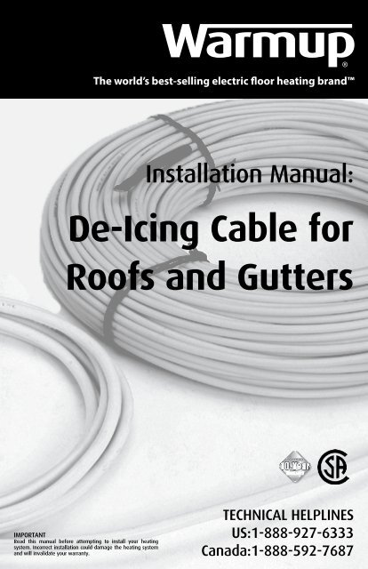
The world’s best-selling electric floor heating br<strong>and</strong><br />
Installation Manual:<br />
<strong>De</strong>-<strong>Icing</strong> <strong>Cable</strong> <strong>for</strong><br />
<strong>Roofs</strong> <strong>and</strong> <strong>Gutters</strong><br />
IMPORTANT<br />
Read this manual be<strong>for</strong>e attempting to install your heating<br />
system. Incorrect installation could damage the heating system<br />
<strong>and</strong> will invalidate your warranty.<br />
TECHNICAL HELPLINES<br />
US:1-888-927-6333<br />
Canada:1-888-592-7687
Table of Contents<br />
Product Specification.....................................................2<br />
Construction of the <strong>Cable</strong>s............................................2<br />
Sizing Guide...................................................................2<br />
Be<strong>for</strong>e Installation......................................................2-3<br />
Control of Roof & Gutter <strong>Cable</strong>.....................................4<br />
Electrical Provisioning...................................................4<br />
Drawing Your Plan........................................................5<br />
Installation.................................................................6-9<br />
Final Installation..........................................................10<br />
<strong>Cable</strong> length needed .................................................10<br />
Warranty.......................................................................11<br />
PRODUCT SPECIFICATION AND DETAILS<br />
The <strong>Warmup</strong> Roof & Gutter Snow Melting/<strong>De</strong>-<strong>Icing</strong> <strong>Cable</strong> has been designed <strong>for</strong> the purpose of<br />
preventing ice buildup [i.e. ice dams] on roofs, gutters <strong>and</strong> downspouts. When properly installed <strong>and</strong><br />
operated, this product creates a path <strong>for</strong> melted snow/ice to drain from the roof to the ground. The cable<br />
has a constant wattage output of 5.5 Watts/ft (18 Watts/m).<br />
Ensure you connect the WRGH <strong>De</strong>-<strong>Icing</strong> <strong>Cable</strong> to either a 120V or 240V, as indicated on the product<br />
label, weatherproof outlet with proper grounding. NEVER ALLOW THE CABLES TO OVERLAP. NEVER<br />
SHORTEN THE HEATER CABLE. Any attempt to alter the cable will void the warranty. The cold lead<br />
CAN be cut/extended to suit the location of the electrical power connection box.<br />
CONSTRUCTION AND SELECTION OF ROOF & GUTTER DE-ICING CABLES<br />
The <strong>Warmup</strong> Roof & Gutter <strong>De</strong>-<strong>Icing</strong> cable consists of a twin conductor resistance heating element<br />
insulated with Fluoropolymer <strong>and</strong> Polyolefin-based compound, which makes the heating cable totally<br />
safe. A metallic sheath is provided to give additional mechanical strength <strong>and</strong> provide ground path. A<br />
final outer jacket of Zero Halogen Polyolefin based compound is given to make it sturdier <strong>and</strong> provide<br />
corrosion protection. The heating cable starts with a 16ft cold lead which can be trimmed as need to<br />
per<strong>for</strong>m the connection to the junction box or controller.<br />
Multiple cables can be combined into a single controller <strong>for</strong> larger installations. Do not ‘daisy-chain’ the<br />
cables, only connect in parallel to the contactors.<br />
See the Sizing Guide below to ensure you have the correct size cable(s) <strong>for</strong> your project.<br />
<strong>Warmup</strong> Roof & Gutter <strong>De</strong>-icing <strong>Cable</strong> Sizing Guide<br />
Length (ft) Heaters Resistance (Ω) Wattage (W) Amps (A)<br />
120 VOLT<br />
240 VOLT<br />
28 WRGH-D-120V-18W/150 92.3 150 1.3<br />
62 WRGH-D-120V-18W/350 41.4 350 2.9<br />
88 WRGH-D-120V-18W/475 30.0 475 4.0<br />
156 WRGH-D-120V-18W/850 16.9 850 7.1<br />
219 WRGH-D-120V-18W/1200 12.0 1200 10.0<br />
93 WRGH-D-240V-18W/500 114.3 500 2.1<br />
176 WRGH-D-240V-18W/950 60.0 950 4.0<br />
250 WRGH-D-240V-18W/1300 44.4 1300 5.4<br />
312 WRGH-D-240V-18W/1700 33.8 1700 7.1<br />
437 WRGH-D-240V-18W/2400 24.0 2400 10.0<br />
625 WRGH-D-240V-18W/3400 16.9 3400 14.2<br />
IMPORTANT INSTRUCTIONS BEFORE INSTALLATION OF THE CABLE<br />
1. It is important to plan how the cable will be arranged BEFORE the cable is laid (see pg 4). The tracer<br />
pattern must be arranged so that it routes melted water from “warm areas” (where ice on the roof<br />
usually melts first) to “cold areas”. See table 2 page 9 <strong>for</strong> to estimate the cable length you need.<br />
2. Be<strong>for</strong>e installing the <strong>De</strong>-<strong>Icing</strong> <strong>Cable</strong>, allow it to warm up to room temperature. The cables should not<br />
be energized above 50°F (10C).<br />
3. Check the continuity, resistance <strong>and</strong> insulation resistance of the <strong>De</strong>-<strong>Icing</strong> <strong>Cable</strong> be<strong>for</strong>e <strong>and</strong> after<br />
installing. Resistance value should match the value shown in the Sizing Guide above. A tolerance of -5%<br />
to +10% is allowed. Insulation resistance must be more than 10 megohms.<br />
2
3<br />
IMPORTANT INSTRUCTIONS BEFORE INSTALLATION OF THE CABLE (cont’d)<br />
4. Do NOT install the cables to remove ice dams that have already <strong>for</strong>med or to clear the roof of ice<br />
<strong>and</strong> snow.<br />
5. Do NOT use the cable <strong>for</strong> any other purpose [i.e. pipes or sidewalks]. <strong>Warmup</strong> offers other snow<br />
melting products designed <strong>for</strong> these purposes. Call 1-888-927-6333 (US) or 1-888-592-7687 (CA) <strong>for</strong><br />
more in<strong>for</strong>mation.<br />
6. Do NOT use <strong>De</strong>-<strong>Icing</strong> cables with wooden gutters or downspouts.<br />
7. The de-icing cable should NEVER OVERLAP OR CROSS AT ANY TIME. This could cause the cable to<br />
overheat, causing damage.<br />
8. <strong>Cable</strong> installation should only be done at between 32°F-81°F (0°C-27°C). Below 32°F shingles are<br />
brittle <strong>and</strong> may break. Above 81°F (27°C), shingles may be warm <strong>and</strong> may tear.<br />
9. In general, apply cables along the roof line; in valleys; in problem areas such as sky lights <strong>and</strong> dormers<br />
<strong>and</strong> nearby gutters/downspouts.<br />
10. Start cable installation at the junction box, leaving a drip loop where the cable exits at the junction<br />
box.<br />
11. Use only recommended types of clips (which will not damage the cables) to attach the cable.<br />
12. Do not attempt to staple or nail the cable or attach the cable with materials such as glue, caulk<br />
or adhesive. Use the P-clips provided to secure the wire. Other methods <strong>for</strong> specific roof types are<br />
available. Consult this manual or call <strong>Warmup</strong> <strong>for</strong> further guidance.<br />
13. To attach the cable properly, it must lie flat in the gutter. To do this, uncoil the cable so that it is not<br />
twisted or tangled.<br />
14. Use the P-clips provided to fasten the cable to the bottom of each drip loop you have <strong>for</strong>med.<br />
15. Keep the cable in the gutter tight <strong>and</strong> off the bottom of the gutter to prevent heat loss.<br />
16. If you are treating only the gutters <strong>for</strong> ice problems, use a “double run” of cable in the gutter <strong>and</strong><br />
downspouts.<br />
17. The recommended distance between clips is about 3ft, although this will vary depending on the<br />
length of cable on the roof slope. Make sure to use a clip at every turn of the cable, <strong>and</strong> call <strong>Warmup</strong><br />
with any questions.<br />
18. Roof & Gutter <strong>De</strong>-icing <strong>Cable</strong>s should be connected to a Ground Fault Circuit Interrupter (GFCI).<br />
Consult a qualified electrician.<br />
WARNING!<br />
The heating cable must NOT be shortened or cut in any manner or subjected to strain at the cable/<br />
splice point.<br />
Connecting the cable to the mains should be undertaken only by an authorized electrician.
IMPORTANT INSTRUCTIONS BEFORE INSTALLATION OF THE CABLE (cont’d)<br />
21. Clear all gutters <strong>and</strong> downspouts of combustible debris such as leaves, pine needles, seeds or<br />
windblown trash (protect h<strong>and</strong>s with gloves) <strong>and</strong> remove any sharp edges that could damage the <strong>De</strong>-<br />
<strong>Icing</strong> cable.<br />
22. For easy reference, fix a label at the power distribution board indicating the location of the <strong>De</strong>-<strong>Icing</strong><br />
<strong>Cable</strong>s installed.<br />
23. Keep the power leads conduit separate from the sensor cable conduit when applicable. See selection<br />
of controls or call <strong>Warmup</strong>.<br />
24. The cables should be connected to a Ground Fault Circuit Interrupter (GFCI) or equivalent having a<br />
rated residual operating current not exceeding 30mA. Consult a qualified electrician.<br />
CONTROLLING YOUR ROOF & GUTTER CABLE INSTALLATION<br />
The <strong>Warmup</strong> WRGH Roof & Gutter <strong>De</strong>-<strong>Icing</strong> <strong>Cable</strong> works most effectively with an automatic thermostat<br />
<strong>and</strong> sensing device. The sensor monitors <strong>for</strong> moisture <strong>and</strong> temperature to maintain the required<br />
temperature. For outdoor mounted controls, use the DS-series of automatic controllers, or <strong>for</strong> indoormounted<br />
devices, select the ETOG module with ETOR roof sensor(s).<br />
When using the WRGH-Kits from <strong>Warmup</strong>, no control device is necessary. Simply plug into an outdoor<br />
rated outlet supplied by a GFCI breaker of the appropriate voltage.<br />
ELECTRICAL PROVISIONS FOR THE SYSTEM<br />
The electrical connections to the <strong>De</strong>-<strong>Icing</strong> <strong>Cable</strong>s shall be in accordance with the National Electrical<br />
Code (in the USA) or Canadian Electrical Code (in Canada).<br />
INSTALLING YOUR ROOF & GUTTER HEATING CABLE<br />
Choose a starting point - Select the starting point of your system by locating the desired placement of<br />
the outdoor electrical outlet (WRGH Kits) or the junction box routing to the controller (WRGH cable).<br />
Make sure to use caution <strong>and</strong> avoid high traffic areas, restrict general access to the cable <strong>and</strong> stay away<br />
from windows, doors <strong>and</strong> other obtrusions.<br />
Plan the pattern on your roof - There are multiple methods <strong>for</strong> applying the cable to the roof <strong>and</strong><br />
gutters as further described in this manual. We recommend you plan a written route <strong>for</strong> the cable to<br />
ensure the most efficient path <strong>and</strong> installation method <strong>for</strong> the heating cable.<br />
Note that the heating cable is specifically intended <strong>for</strong> problem areas <strong>and</strong> does not need to be installed<br />
on all areas of the roof. In some instances, on high-pitched roofs (over 40 degree slope) <strong>and</strong> on roofs<br />
with minimal overhang, no cable on the actual roof line may be required. However, always ensure to<br />
create a path <strong>for</strong> the ice to melt from the roof to the ground, placing cable on the roof, in the gutters <strong>and</strong><br />
in the downspouts as necessary. Extend the cable about 1’ out of the bottom of the downspout (surface)<br />
or about 1’ below the frost line. As a reference, the frost line in cold areas is typically 20” to 30” deep.<br />
4
5<br />
PLANNING YOUR LAYOUT<br />
Draw a plan showing the layout <strong>and</strong> location of the snow melting cables below <strong>and</strong> keep it <strong>for</strong> future<br />
reference.<br />
<strong>Warmup</strong>’s 24/7 Toll Free Technical Number: 1-888-927-6333 / 1-888-592-7687
6<br />
INSTALLATION INSTRUCTIONS FOR THE ROOF& GUTTER DE-ICING CABLE<br />
FIGURE 1: Typical pattern along roof line <strong>and</strong> in gutters/downspouts.<br />
TIP: If you will be working directly on the roof during the installation, you may want to mark the cable<br />
pattern with chalk be<strong>for</strong>e attaching the cable. If working from a ladder, you will probably want to lay<br />
out the pattern as you attach the cable with the clips. Making a drawing of your roof <strong>and</strong> your planned<br />
pattern on paper is recommended.<br />
Pattern <strong>for</strong> the roof line: The cable laid along the roof line is arranged in a triangular pattern (see<br />
Figure 2). The cable MUST extend above the overhang into the warm section of the roof. To determine<br />
the height of the triangles, measure the depth of the overhang. The triangle heights are measured by<br />
the number of shingle rows from the roof edge (based on the st<strong>and</strong>ard 5½ inch tab shingles). Using<br />
Table 1 (see following page), determine the height of each triangle. Using this method, the triangles will<br />
extend at least one shingle row (5½ inches) into the warm roof area.<br />
Triangle<br />
Height<br />
Triangle Base<br />
(15 inches)<br />
FIGURE 2: Triangle pattern along the roof line.<br />
Pattern <strong>for</strong> the sky lights: Problem sky light areas are also treated with the “triangle pattern” approach.<br />
However, the height of the triangles may need to be greater than those along the roof line. Increase the<br />
triangle height so that it extends to one shingle row (5½ inches) below the sky light. The triangle base<br />
is maintained at 15 inches (see Figure 3).<br />
FIGURE 3: Triangle pattern near sky light
Table 1 - Triangle Heights <strong>for</strong> Various Overhangs<br />
OVERHANG<br />
(inches)<br />
TRIANGLE HEIGHT<br />
(shingle rows)<br />
Less than 12 3<br />
12-18 4<br />
18-24 5<br />
24-30 6<br />
30-36 7<br />
36-42 8<br />
OVERHANG<br />
(inches)<br />
TRIANGLE HEIGHT<br />
(shingle rows)<br />
42-48 9<br />
48-54 10<br />
54-60 11<br />
60-66 12<br />
66-72 13<br />
Pattern <strong>for</strong> valleys: If a valley exists in a problem area of your roof, you must route cable up <strong>and</strong> back<br />
down the valley a minimum of 3 feet, as shown in Figure 4. Extend the cable higher if the warm area of<br />
your roof is higher.<br />
FIGURE 4: <strong>Cable</strong> pattern in a valley<br />
Pattern <strong>for</strong> dormers: To treat a problem dormer area, the cable should be arranged up <strong>and</strong> around the<br />
dormer as shown in Figure 5.<br />
FIGURE 5: <strong>Cable</strong> pattern around a dormer<br />
7
8<br />
INSTALLATION INSTRUCTIONS FOR THE ROOF & GUTTER DE-ICING CABLE (cont’d)<br />
Pattern <strong>for</strong> other special roof areas - Other problem roof areas not previously described may also be<br />
treated with the de-icing cable to prevent ice dam <strong>for</strong>mation. Triangles - similar to those used <strong>for</strong> the<br />
roof line can also be used to treat these special areas.<br />
In treating these special problem areas, the height of the triangles may be greater than those used at<br />
the roof edge. Keep the triangle based at 15 inches, but increase the triangle height so it extends at least<br />
one shingle row (5½ inches) into the warm roof section.<br />
Triangle heights must NOT exceed 5 feet. The clips provided with the kit are not designed to attach<br />
triangles this large. For problem areas that are more than 5 feet from the roof edge, commercial grade<br />
de-icing cable should be installed by a professional installer.<br />
ROUTING OF CABLES IN DOWNSPOUTS USING CABLE CLIPS<br />
“Along run” downspouts - For downspouts that are along the run of the roof line being treated, the<br />
cable must be routed down <strong>and</strong> back up the inside of the downspout. Do NOT wrap the cable around the<br />
downspout or otherwise attempt to attach it to the outside.<br />
Remember: to avoid overheating the cable <strong>and</strong> increasing the risk of fire or electric shock, no part of<br />
the downspout may pass through a building.<br />
You must first determine the total length of cable needed to go down <strong>and</strong> back up the downspout. It<br />
is important to measure as accurately as possible because the cable must be flush with the end of the<br />
downspout. Several methods <strong>for</strong> determining the length may be used. One is to tie a small weight (such<br />
as washer) to a string <strong>and</strong> lower it into the downspout. Once the string passes through the bottom of the<br />
downspout, mark the string as needed to record the length of the downspout. You will need twice this<br />
length of cable. (Note: <strong>for</strong> accurate results, use a string that does NOT stretch when the small weight<br />
is attached).<br />
Alternatively, you could also use a tape to measure each section of the downspout. To calculate the total<br />
cable needed, add the measurements in each section <strong>and</strong> multiply by 2.<br />
Lastly, if it is not possible to use either of these above methods, you may use the cable itself to estimate<br />
the length of cable needed in the downspout. However, to avoid snagging or cutting the cable on sharp<br />
edges, take care when pulling the cable into <strong>and</strong> removing it from the downspout. Inspect the cable <strong>for</strong><br />
damage <strong>and</strong> do NOT use a cable that has been damaged.<br />
Once you know the length of the cable needed, the next step is to install clips <strong>and</strong> feed the cable into<br />
the downspout. Use the clips as a spacer on the cable every 6 inches so that the cable does not touch<br />
itself in the downspout. You must tighten the spacers be<strong>for</strong>e the cable is installed in the downspout. You<br />
may do this with your fingers or pliers. If you use pliers, squeeze gently <strong>and</strong> use care to avoid pinching,<br />
crimping, cutting into or otherwise damaging the cable. Do NOT hammer to tighten the clips. Pull the<br />
cable into the downspout using a weight string.<br />
<strong>Warmup</strong> Roof Clips NAM-ROOF-CLIP
9<br />
“End of run” downspouts - If a downspout exists at the end of the run of the roof line being treated, the<br />
cable must be routed down the inside of the downspout. There is no need to route it back up. Do NOT<br />
wrap the cable around the downspout or attempt to attach it to the outside.<br />
Pull cable into downspouts using weighted string. Be sure the run of the cable is flush with the end of<br />
the downspout <strong>and</strong> that no cable is extended out at the end of the downspout. Remember to avoid<br />
overheating the cable <strong>and</strong> increasing the risk of fire or electric shock.<br />
NO part of the downspout may pass through a building.<br />
FIGURE 6a: <strong>Cable</strong> routed back along the roof line in the gutter <strong>and</strong> downspouts.<br />
If at this point you find that you have an excess of cable, you may route the cable back up the downspout<br />
to take up this excess. Alternatively, triangles on the roof can be made larger (up to 5 feet in length) or<br />
cable loops in valleys can be extended.<br />
FIGURE 6b: <strong>Cable</strong> routed back along the roof line in the gutter <strong>and</strong> downspouts.<br />
If you have a shortage of cable (the end of the cable does NOT reach to the bottom of the downspout),<br />
you may to reduce the height of the triangles on areas of the roof that are less susceptible to ice dams.<br />
When transferring from gutter to downspout, in-line or at end-of-run, always use a WARMUP Downspout<br />
Hanger clip to prevent the cable from chafing against the sharp sheet metal edges of the gutter. Refer<br />
to the specific instructions to apply such clip.<br />
The above instructions assume ‘residential’ type gutters <strong>and</strong> spouts between 4” <strong>and</strong> 6” wide. For roof<br />
draining larger than that <strong>and</strong> applications that may require above normal melting, please consult a<br />
<strong>Warmup</strong> representative <strong>and</strong> discuss your options with Commercial grade Self Regulating <strong>Cable</strong>.<br />
WARNING!<br />
To reduce the risk of fire, electric shock or ice dam <strong>for</strong>mation,<br />
do NOT cut splice or alter the de-icing cables in any way.<br />
The cable length CANNOT be changed.
10<br />
FINAL INSTALLATION STEP<br />
Check to be sure that the cable has NOT been removed from its intended position.<br />
The heated portion of the cable MUST be positioned entirely on the roof <strong>and</strong> MUST NOT touch, cross<br />
over or overlap itself.<br />
Place the labels <strong>for</strong> the Circuit Breaker / Fuse Panel near the appropriate circuit breaker / fuse so<br />
that they are clearly visible to current <strong>and</strong> future users.<br />
Table 2 - Estimating the cable length you need<br />
AREA WHAT TO MEASURE HOW TO CALCULATE<br />
Along Roof Overhang (A) <strong>and</strong> Length of Roof (B) Length of roof (B) x Overh<strong>and</strong> Multiplier (see below)<br />
Dormer Distance around dormer (C) Number of dormers x Distance around dormers (C)<br />
Valley Number of valleys (D) Number of valleys (D) x 6 feet (1.8m)<br />
Downspout Number of downspouts Length of downspouts (E) Number of downspouts x Length of downspouts (E) x 2<br />
Table 3 - Overhang Multiplier<br />
Inches<br />
ROOF OVERHANG<br />
Centimeters<br />
MULTIPLIER FOR ROOF<br />
WITH GUTTERS<br />
MULTIPLIER FOR ROOF<br />
WITHOUT GUTTERS<br />
Less than 12 Less thn 30 4.0 3.0<br />
12 30 4.0 3.0<br />
24 60 5.3 4.3<br />
36 90 6.8 5.8<br />
48 120 8.1 7.1<br />
60 150 9.6 8.6<br />
72 180 11.2 10.2
WARRANTY - Roof & Gutter <strong>De</strong>-icing cables<br />
<strong>Warmup</strong> provides a 10-Year Warranty (from date of purchase) <strong>for</strong> the Snow Melting Mats <strong>and</strong> <strong>Cable</strong>s <strong>for</strong> the material<br />
<strong>and</strong> workmanship under normal operating conditions.<br />
In case of defective material, <strong>Warmup</strong>’s obligation will be limited to the repair or supply of new material, free of charge<br />
to the customer.<br />
The Warranty does NOT cover installations made by unqualified personal or faults caused by incorrect design by<br />
others; misuse; damage caused by others; damage in transit; incorrect installation <strong>and</strong> any other subsequent damage<br />
that may occur. Cost related to repair/replacement will be fully chargeable to the customer if the damage is due to<br />
any of the above reasons.<br />
<strong>Warmup</strong> is under no circumstances liable <strong>for</strong> consequential damages or losses including without limitations the loss<br />
or profit arising from any cause whatsoever. The guarantee is a material warranty only <strong>and</strong> does NOT cover field labor.<br />
A qualified electrician MUST connect the heating system.<br />
The Warranty is void if there is any payment default <strong>and</strong> if data is not filled in correctly.<br />
EXCLUSIONS<br />
<strong>Warmup</strong>, Inc. shall in no event be liable <strong>for</strong> incidental or consequential damages, including but not limited to extra<br />
utility expenses or damages to property. This Warranty is null <strong>and</strong> void if:<br />
1) The covering over the heater(s) is damaged, lifted, replaced, drilled into or repaired.<br />
2) The heater fails due to damage caused during installation, unless damage is caused directly by an employee of<br />
<strong>Warmup</strong>. It is there<strong>for</strong>e essential to check that the heater is working (as specified in the installation manual) prior <strong>and</strong><br />
during installation.<br />
3) Damage as a result of floods, fires, winds, lightning, accidents, corrosive atmosphere or other conditions beyond the<br />
control of <strong>Warmup</strong>, Inc.<br />
4) Use of components or accessories is not compatible with <strong>Warmup</strong> heaters.<br />
5) <strong>Warmup</strong> products are installed outside the United States.<br />
6) Parts not supplied or designated by <strong>Warmup</strong>, Inc.<br />
7) Damage or repair required as a result of any improper use, maintenance, operation or servicing.<br />
8) Failure to start due to interruption <strong>and</strong>/or inadequate electrical service.<br />
9) Any damage caused by frozen or broken pipes in the event of equipment failure.<br />
10) Changes in the appearance of the product that does not affect its per<strong>for</strong>mance.<br />
11) The owner, or his/her designated representative, attempts to repair the product without receiving prior authorization<br />
from <strong>Warmup</strong>. Upon notification of a repair problem, <strong>Warmup</strong>, Inc. will issue an Authorization to Proceed under the<br />
terms of this Warranty. If <strong>Warmup</strong> is required to inspect or repair any defects caused by any exclusions referenced<br />
above, all work will be fully chargeable at <strong>Warmup</strong>’s inspection <strong>and</strong> repair rates then in effect.<br />
WARMUP, INC. DISCLAIMS ANY WARRANTY NOT PROVIDED HEREIN, INCLUDED ANY IMPLIED WARRANTY OF THE<br />
MERCHANTABLE OR IMPLIED WARRANTY OF FITNESS FOR A PARTICULAR PURPOSE. WARMUP, INC. FURTHER<br />
DISCLAIMS ANY RESPONSIBILITY FOR SPECIAL, INDIRECT, SECONDARY, INCIDENTAL, OR CONSEQUENTIAL DAMAGES<br />
ARISING FROM OWNERSHIP OR USE OF THIS PRODUCT, INCLUDING INCONVENIENCE OR LOSS OF USE. THERE<br />
ARE NO WARRANTIES THAT EXTEND BEYOND THE FACE OF THIS DOCUMENT. NO AGENT OR REPRESENTATIVE<br />
OF WARMUP, INC. HAS ANY AUTHORITY TO EXTEND OR MODIFY THIS WARRANTY UNLESS SUCH EXTENSION OR<br />
MODIFICATION IS MADE IN WRITING BY A CORPORATE OFFICER.<br />
DUE TO DIFFERENCES IN BUILDING AND FLOOR INSULATION, CLIMATE AND FLOOR COVERINGS, WARMUP, INC.<br />
MAKES NO REPRESENTATION THAT THE FLOOR TEMPERATURE WILL ACHIEVE ANY PARTICULAR TEMPERATURE<br />
OR TEMPERATURE RISE. UL STANDARD LISTING REQUIREMENTS LIMIT THE HEAT OUTPUT OF WARMUP UNDERTILE<br />
HEATING, AS SUCH, USERS MAY OR MAY NOT BE SATISFIED WITH THE FLOOR WARMTH THAT IS PRODUCED.<br />
WARMUP DOES WARRANT THAT ALL HEATERS WILL PRODUCE THE RATED WATT OUTPUT LISTED ON THE HEATER<br />
NAMEPLATE, WHEN OPERATED AT THE RATED VOLTAGE.<br />
TERMS AND CONDITIONS<br />
Shipping Discrepancies:<br />
Incoming materials should be inventoried <strong>for</strong> completeness <strong>and</strong> <strong>for</strong> possible shipping damage. Any visible damages<br />
or shortages must be noted prior to accepting the material. Any discrepancy concerning type or quantity of material<br />
shipped, must be brought to the attention of your <strong>Warmup</strong>® reseller within 15 days of the shipping date entered on<br />
the packing slip <strong>for</strong> the order.<br />
Miscellaneous:<br />
The terms of this Limited Warranty are exclusive <strong>and</strong> supersede any other warranty or terms <strong>and</strong> conditions relating<br />
to the subject matter whether included in a purchase order <strong>for</strong> this product or in any other document or statement.<br />
11
Register your <strong>Warmup</strong> warranty at<br />
www.warmup.com or www.warmup.ca<br />
<strong>Warmup</strong> Offices in North America:<br />
USA: <strong>Warmup</strong> Inc | 52 Federal Road Unit 1F Danbury CT 06810<br />
Tel 1-888-927-6333 | Fax 1-888-927-4721<br />
E-mail us@warmup.com | Web www.warmup.com<br />
CANADA: <strong>Warmup</strong> Inc | 4 Robert Speck Parkway, Suite 1500<br />
Mississauga, Ontario L4Z 1S1<br />
Tel 1-888-592-7687 | Fax 905-366-7324<br />
E-mail ca@warmup.com | Web www.warmup.ca<br />
12<br />
V. 11.12