In-slab Floor Heating Cable - Warmup
In-slab Floor Heating Cable - Warmup
In-slab Floor Heating Cable - Warmup
- No tags were found...

Create successful ePaper yourself
Turn your PDF publications into a flip-book with our unique Google optimized e-Paper software.
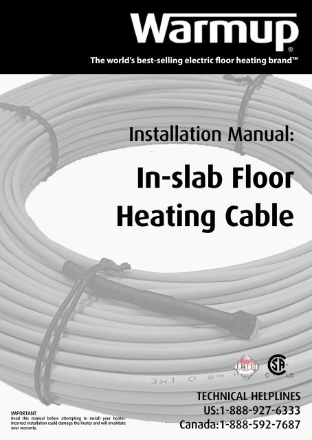
The world’s best-selling electric floor heating brand<strong>In</strong>stallation Manual:<strong>In</strong>-<strong>slab</strong> <strong>Floor</strong><strong>Heating</strong> <strong>Cable</strong>IMPORTANTRead this manual before attempting to install your heater.<strong>In</strong>correct installation could damage the heater and will invalidateyour warranty.TECHNICAL HELPLINESUS:1-888-927-6333Canada:1-888-592-7687
ContentsDo’s and Don’ts 2The product 3Subfloor considerations 4<strong>In</strong>stallation layouts 9<strong>In</strong>stalling multiple heaters 10<strong>In</strong>stallation steps 11-19Spacing guides 13-14Warranty / Terms and Condition 20-21Warranty registration form 22Do’s & Dont’sThe cable must be spaced evenly at all times to ensure an evenly heatedfloor. The bend radius of the wire must NOT be less than 2” (50mm).The cables must never touch or cross each other (min separation is2”[50mm]).The cable must not be cut, damaged or shortened.The entire cable, including joints, must be laid under the floor <strong>slab</strong>.<strong>In</strong>stallation of the cable onto a new concrete floor should not becarried out for approximately 30 days to allow the concrete to cure.Do not install the cable up walls.NEVER install cables directly onto insulation boards.If these instructions are followed, you should have no problems,however if you require assistance at any stage, please call ourhelpline on:21-888-927-6333 (US)1-888-592-7687 (Canada)
The ProductThis product is a <strong>Warmup</strong>® <strong>In</strong>-<strong>slab</strong> <strong>Heating</strong> <strong>Cable</strong>. The cable has been designed to beplaced within a <strong>slab</strong> of at least 2” (50mm) in thickness. The cable is a twin conductorsurrounded by a ground shield for electrical protection. The cable is supplied with a 16’4” cold tail for connection to a thermostat.Advanced fluoropolymers insulationCoreReturn braidEarth braidSheathThe product is designed for a 120V/240V electrical supply - ensure the correct heaterfor the correct power supply has been purchased. The cable produces between 10 to 20Watts per sqft (100W to 200W/SQM) of heating, depending on the spacing of the cable(see Sizing Guide at the back of the manual). The product is CSA approved.ELECTRICAL CONSIDERATIONSBefore installing the heating cable, a suitable 120V/240V electrical supply must belocated. The heating system requires a GFCI [ground fault circuit interrupter], either inthe breaker box OR in the thermostat. The wiring must be capable of the load requiredby the thermostat. All electrical installations must be carried out by a qualified electricianin accordance with local building and electrical codes, the NEC (especially article 424,part V of the NEC, ANSI/NFPA 70 in the US) or the CEC Part I (in Canada).The installation of more than one cable will require ALL the cold tails to be connectedto the thermostat in parallel and NOT series. <strong>In</strong>stallations involving more than 2 heatingcables may require a junction box. The cold tail consists of three (3) wires: live; neutraland ground. These should all be connected within the thermostat. Caution should betaken to ensure that the combination of heaters does not exceed the maximum 15amps supplied by the thermostat - see Heater Sizing & Wiring Spacing Guide on theback cover for amperage calculations.The heating cable must not be cut or shortened or subjected to strain.The cold tail can be shortened if required.NOTE: it is required that power to this product is supplied by a thermostat and GFCI.ALL electrical connections must be carried out by a qualified electrician.ALL electrical regulations must be observed, including national and local codes.3
Subfloor considerationsThe <strong>Warmup</strong>® <strong>In</strong>-<strong>slab</strong> <strong>Heating</strong> <strong>Cable</strong> is designed to be placed within the cementitious<strong>slab</strong> of at least 2” (50mm) in thickness, with at least 1¹/₈” (30mm) of <strong>slab</strong> above theheating wire. Depending on the construction of the subfloor, you may need to useadditional insulation with your installation. See the diagrams below for details.A. IF CONCRETE SLAB IS LESS THAN OR EQUAL TO 4” (100mm) & INSULATED:You may install the heating cable directly on top of the concrete <strong>slab</strong>B. IF CONCRETE SLAB IS MORE THAN 4” (100mm) OR UNINSULATIED:You may install insulation before laying the heating cableThe subfloor of the project should be suitable for concreting. The floor shouldbe rigid, of a suitable material and free of debris and dust. Any holes in the floorshould be sealed or filled with a suitable material. Any sharp objects or materialswhich may potentially damage the heating cable should be removed.4
<strong>In</strong>stallation (using fixing strips)It is advised that a floor plan is drawn up todetermine the placement of the thermostat,heating cable and the sensor probe. This diagramshould be kept for future reference.The fixing strips should be laid out perpendicularto the heating cable runs. These fixing strips mustbe secured to the insulation or the concrete floorusing fixing nails or an adhesive. It is important toensure there is no movement of the fixings.The fixing strips should be evenly spread acrossthe floor at interval of 30” (0.75m). The fixing stripsshould be placed so as to leave a minimum of 4”(100mm) border all the way around the room.Examine the cable and test the resistance BEFOREand AFTER installation. Always record readings inthe NOTES Section.The heating cable should then be laid up and downthe room and clipped into the fixing strip. Thecable spacing is determined by the product model(see Sizing Guide on back). The cables should bespaced evenly at all times to ensure an evenlyheated floor (minimum spacing is 2” (50mm). Thecables should never touch or cross each other.The heating cable cold tail should be connectedto the thermostat by a qualified electrician inaccordance with NEC (USA) and CEC Part 1 (Canada).The heating cables should then be tested againBEFORE POURING the layer of cement. Recordthe readings in the NOTES Section. Once laid, theheating cables must be covered with a minimumthickness of 1¹/₈” (30mm) of cement.ABC30”(0.75m)Lay out fixing stripsLay out heating cableClip cable to fixingstrips5
<strong>In</strong>stallation (using Reinforcement Bars)Pre-<strong>In</strong>stallation <strong>Floor</strong> Preparations1. Prepare floor plan of the area requiring the <strong>slab</strong> heating system & note the areato be heated.2. If installing the cable to reinforcement bars in poured concrete, the re-bars mustbe grounded.3. Identify a suitable location for installing the power supply box thermostat andsensor.4. Visually check the <strong>Warmup</strong> <strong>In</strong>-Slab <strong>Heating</strong> <strong>Cable</strong> in the box and make sure thatit is not in a damaged condition.5. Check voltage, wattage and resistance values from the factory test record givenalong with the product and that it matches the required specifications. Recordreadings in the NOTES Section of this manual in order to complete the onlinewarranty later.6. Check the resistance of heating cable and its insulation resistance with a digitalmulti-meter as soon as you remove it from its packing. The resistance value ofthe heating cable must match the value given in product range table. A toleranceof -5% to +10% is allowed. <strong>In</strong>sulation resistance must be more than 10Mohms.Record readings in the NOTES Section until you can complete the online warranty.<strong>In</strong>stallation on Reinforcement Bars<strong>Warmup</strong> <strong>In</strong>-Slab <strong>Cable</strong>s are suitable for attaching to the reinforcing steel bars inconcrete from a depth of, 1.5” to 3.0” below the surface. Only one cold tail at oneend exists, simplifying the installation. The heating cable must not be cut orshortened and must be GFCI protected.1. Once the on-centre-spacing (OC) has been worked out the cables can be tiedto the re-bars using plastic cable ties. Care must be taken not to tighten the tiestoo much causing damage to the cable. Any number of ties can be used ensuringthat the on-centre-spacing is maintained. For ease of installation, cable lengthscan be determined to match the re-bar spacing. For an 8” re-bar spacing (200mm),measure the area to be heated in sq ft, multiply this by 12 and then divide by 8”. Thisgives you the length of cable in feet.6
<strong>In</strong>stallation (using Reinforcement Bars - continued)2. Position cables to avoid water pipes, baths and permanent fixtures that will beinstalled on the finished floor with nails or similar fixings. Perimeter cables shouldbe run with 4” minimum distance from walls and permanent fixtures.3. Sketch the location of: cables, remote sensor conduit, cold tail joint to heatingcable and the junction box with neutral and live connections. Provide an installationcopy for any future modifications/ renovations etc.4. The single cold tail screen goes to ground. Being a dual core cable, the cold tailalso has twin cores for the neutral and live connections.5. <strong>In</strong>stall a half inch conduit from the location of the thermostat box down the wallto the edge of where the floor is to be heated. This conduit will house the coldtail lead. The joint or splice to the heater wire must be visible and away from thebottom of the conduit. If using multiple cables, route all the power from the heatedpart of the floor up through the conduit and into the thermostat box. It is advisableto use a conduit for each cold tail to be taken to the wall location of the thermostatbox. A separate conduit is to be used to run the sensor wire to the main section ofthe floor.6. The conduit housing the sensor wire is to be curved up between the heatingcables with the opening above the intended surface level of the concrete <strong>slab</strong>, withthe end capped to prevent debris falling into the conduit.7. Check the continuity, resistance and insulation resistance value during and afterlaying the heater wires. Check if these values are consistent with pre-install values.Record the values for the online warranty registration.8. Once the cable has been installed, the sensor wire conduit positioned and thefinal resistances and continuity checked, the concrete floor can then be poured.Care must be taken not to damage the heater wires when the concrete is pouredwith operatives walking on the re-bars.9. Ensure the entire heating cable, joints or factory splices and thermostat conduitsensor is embedded in the concrete mortar. The choice and application ofbuilding material should be in accordance with building materials manufacturer’sinstructions.7
<strong>In</strong>stallation (using Reinforcement Bars - continued)10. Once the concrete has been poured, it is imperative to check that the resistanceand continuity values are consistent with the values taken BEFORE and DURING theinstallation. If these values are not consistent, damage to the heater wires mayhave occurred and a <strong>Warmup</strong> technician must be called on 1-888-927-6333 inthe US or 1-888-5-WARMUP in Canada.12. Ensure the correct maturity and curing times for drying of construction materialsis followed before you begin powering ON the heating cables.13. Once the concrete has dried completely cut the conduit that is raised above thesurface to the level of the concrete.14. Feed the sensor wire from the thermostat box so that the tip of the sensor is juston top of the surface of the new concrete.15. Once the sensor is in place, cement the tip with fresh mortar ensuring that itremains visible at the surface.16. Care must be taken not to damage the tip prior to installing the floor finish.17. <strong>Warmup</strong> recommends up to 8 weeks of curing time before powering up thecables. However, check with your concrete contractor and/or manufacturer forexact curing times. Please note that outside temperatures may affect the curingtime.18. Connection of the cold tail leads, sensor wire and mains supply must beconducted by a qualified electrician in accordance with the thermostat’s instructionmanual.Finished <strong>Floor</strong> Surface CoveringAny surface finish (tile, laminate, wood, carpet, cork, vinyl etc.) can be applied overthe finished concrete <strong>slab</strong>. However, care must be taken at all times that screws ornails used to attach floor coverings do not damage the heating cables. For woodenfloors it is recommended that these be free floating floors and that the <strong>slab</strong> surfacetemperature does not exceed the allowable temperature stated by the woodflooring manufacturer.8
Connect Thermostat and Testing<strong>In</strong>structions for fitting the <strong>Warmup</strong>® Thermostatcan be found inside the thermostat box.DThe thermostat’s sensor probe can be installed anumber of ways:1. Placed directly in the top ³/₈” (10mm) of the <strong>slab</strong>covering the heating wire.2. Cemented into a channel cut out of the surfaceof the <strong>slab</strong>.3. Placed in a flexible conduit in the top ³/₈” (10mm)of <strong>slab</strong>.The heating cables should be tested and readingsrecorded, to ensure the resistance is correct forthe cable supplied (plus or minus 5%). Visualinspection of the cable should also be carriedout to ensure there is no physical damage. Thetesting should be carried out before the cable islaid and after cable has been installed to ensure nodamage has occurred during installation. If thesereadings are incorrect, please call our helpline on1-888-927-6333 for the US and Canada.DO NOT CONCRETE if the heater is notworking.EThe heating cables should be tested and record readings again afterlaying concrete. The heating can be turned on after 28 days, after the <strong>slab</strong>has had time to dry completely.IMPORTANTThe heating cable must be kept a minimum of 2” (50mm) apart at all times.The heating cable must not be cut, damaged or shortened.The entire heating cable and joint must be laid under the floor <strong>slab</strong>.<strong>In</strong>stallation of the heating wire on to a new concrete floor should NOT be carried out forapproximately 30 days to allow the concrete to dry.If these instructions are followed, you should have no problems. However, if yourequire assistance at any stage, please call our helpline on 1-888-927-6333 (US) or1-888-592-7687 (Canada).9
WARMUP, INC. DISCLAIMS ANY WARRANTY NOT PROVIDED HEREIN, INCLUDED ANY IMPLIED WARRANTYOF THE MERCHANTABLE OR IMPLIED WARRANTY OF FITNESS FOR A PARTICULAR PURPOSE. WARMUP, INC.FURTHERDISCLAIMS ANY RESPONSIBILITY FOR SPECIAL, INDIRECT, SECONDARY, INCIDENTAL, OR CONSEQUENTIALDAMAGES ARISING FROM OWNERSHIP OR USE OF THIS PRODUCT, INCLUDING INCONVENIENCE OR LOSSOF USE. THERE ARE NO WARRANTIES THAT EXTEND BEYOND THE FACE OF THIS DOCUMENT. NO AGENT ORREPRESENTATIVE OFWARMUP, INC. HAS ANY AUTHORITY TO EXTEND OR MODIFY THIS WARRANTY UNLESS SUCH EXTENSION ORMODIFICATION IS MADE IN WRITING BY A CORPORATE OFFICER.DUE TO DIFFERENCES IN BUILDING AND FLOOR INSULATION, CLIMATE AND FLOOR COVERINGS, WARMUP, INC.MAKES NO REPRESENTATION THAT THE FLOOR TEMPERATURE WILL ACHIEVE ANY PARTICULAR TEMPERATUREOR TEMPERATURE RISE.CSA STANDARD LISTING REQUIREMENTS LIMIT THE HEAT OUTPUT OF WARMUP UNDER FLOOR HEATING, ASSUCH,USERS MAY OR MAY NOT BE SATISFIED WITH THE FLOOR WARMTH THAT IS PRODUCED. WARMUP DOESWARRANT THAT ALL HEATERS WILL PRODUCE THE RATED WATT OUTPUT LISTED ON THE HEATER NAMEPLATE,WHENOPERATED AT THE RATED VOLTAGE.TERMS AND CONDITIONSShipping Discrepancies:<strong>In</strong>coming materials should be inventoried for completeness and for possible shipping damage. Anyvisible damages or shortages must be noted prior to accepting the material. Any discrepancy concerningtype or quantity of material shipped, must be brought to the attention of your <strong>Warmup</strong>® reseller within15 days of the shipping date entered on the packing slip for the order.Miscellaneous:The terms of this Limited Warranty are exclusive and supercede any other warranty or terms andconditions relating to the subject matter whether included in a purchase order for this product or in anyother document or statement.<strong>Warmup</strong> Canadian 10-Year Warranty<strong>Warmup</strong> provide a warranty for the <strong>Heating</strong> <strong>Cable</strong>s for a period of 10 years from date of shipment,for the material and workmanship under normal operating conditions and completion of the <strong>Warmup</strong>online warranty. <strong>In</strong> case of defective material, <strong>Warmup</strong>’s obligation will be limited to repair or supplyof new material, free of charge to the customer.The warranty does not cover installations made by unauthorized persons or faults caused byincorrect design by others / misuse / damage caused by others / damage in transit / incorrectinstallation and any other subsequent damage that may occur. Repair / replacement will be fullychargeable if the damage is because of any of the above reasons.<strong>Warmup</strong> under no circumstances is liable for consequential damages or losses including withoutlimitations the loss of profit arising from any cause whatsoever. The guarantee is a material warrantyonly and does not cover installation labour.NOTE: All spacings have been based on square areas for calculation purposes. Therefore actual spacing willvary according to the shape of the area to be heated. All spacings should be measured from the centre of thewire.<strong>Warmup</strong> <strong>In</strong>c USA 52 Federal Road | Unit 1F | Danbury | CT 06810 | T: 888-927-6333 | F: 888-927-4721E: us@warmup.com | warmup.com<strong>Warmup</strong> <strong>In</strong>c Canada 10 Kingsbridge Garden Circle | Suite 704 | Mississauga, ON L5R 3K6 | T: 888-592-7687F: 905-990-1732 | E: ca@warmup.com | warmup.caV11-11The WARMUP word and associated logos are trade marks. © <strong>Warmup</strong> Plc. 2007 – Regd. TMNos. 1257724, 4409934, 4409926, 5265707. E & OE.