XRD Analysis of Carbide Phase in Heat Resistant Steels
XRD Analysis of Carbide Phase in Heat Resistant Steels
XRD Analysis of Carbide Phase in Heat Resistant Steels

You also want an ePaper? Increase the reach of your titles
YUMPU automatically turns print PDFs into web optimized ePapers that Google loves.
ISSN 1392–1320 MATERIALS SCIENCE (MEDŽIAGOTYRA). Vol. 12, No. 3. 2006<br />
<strong>XRD</strong> <strong>Analysis</strong> <strong>of</strong> <strong>Carbide</strong> <strong>Phase</strong> <strong>in</strong> <strong>Heat</strong> <strong>Resistant</strong> <strong>Steels</strong><br />
Arūnas BALTUŠNIKAS ∗ , Rimantas LEVINSKAS<br />
Lithuanian Energy Institute, Breslaujos 3, LT-44403 Kaunas-35, Lithuania<br />
Received 03 June 2005; accepted 13 March 2006<br />
In this article we have demonstrated the possibility to perform a quick and rather complete estimation <strong>of</strong> carbide phase<br />
evolution <strong>in</strong> power plant steels us<strong>in</strong>g X-ray diffraction. The distribution <strong>of</strong> alloy<strong>in</strong>g elements <strong>in</strong> the pipel<strong>in</strong>e steels after<br />
long-time operation was exam<strong>in</strong>ed. This important factor <strong>of</strong> steel’s obsolescence and properties change was measured by<br />
identify<strong>in</strong>g carbide phases from the <strong>XRD</strong> powder patterns. The accomplished <strong>XRD</strong> analysis <strong>of</strong> the carbide phases allows<br />
to state that only steel 12Х1MФ exploited for 1.42·10 5 hours and partly steel 12X1MФ exploited for 1.51·10 5 hours meet<br />
the requirements <strong>of</strong> exploitation structure. However for the rest steels, the regenerative heat treatment should be<br />
projected. Additionally we have shown the possibility to do the regenerative heat treatment for our exam<strong>in</strong>ed steels and<br />
the changes <strong>of</strong> carbide phases <strong>in</strong> these steles have been analyzed.<br />
Keywords: <strong>XRD</strong>, power plant, heat resistant steel, creep, ferrite, pearlite, alloy carbide, cementite, regenerative heat<br />
treatment, electrochemical etch<strong>in</strong>g.<br />
1. INTRODUCTION ∗<br />
Thermal power stations equipment operat<strong>in</strong>g resource<br />
depends on the changes <strong>of</strong> the metal microstructure that<br />
appear dur<strong>in</strong>g the creep process. Therefore, when<br />
evaluat<strong>in</strong>g operat<strong>in</strong>g resource <strong>of</strong> power plant equipment<br />
components and predict<strong>in</strong>g tools to extend it, the long-term<br />
periodical analysis <strong>of</strong> the permanent deformations <strong>of</strong> steels<br />
is performed [1].<br />
Deformation and breakage <strong>of</strong> heat resistant steel <strong>of</strong>ten<br />
happens with<strong>in</strong> the boundaries <strong>of</strong> the gra<strong>in</strong>s. Steel<br />
resistance for the heat is <strong>in</strong>creased alloy<strong>in</strong>g the solid<br />
solution. A special alloy structure is formed where small<br />
carbide gra<strong>in</strong>s are <strong>in</strong>serted <strong>in</strong>to the base solid alloy and<br />
positioned along the boundaries <strong>of</strong> the matrix gra<strong>in</strong>s.<br />
Intermetallic phase coherently tied with the matrix is also<br />
formed here. Dislocations are retarded when they confront<br />
those phases. The smaller are the phases and the bigger is<br />
the amount <strong>of</strong> them – the more <strong>in</strong>tense is the retard<strong>in</strong>g and<br />
the bigger is the resistance to the creep [2, 3].<br />
The important factor <strong>of</strong> ferritic steels obsolescence and<br />
properties change is alloy<strong>in</strong>g elements diffusion from<br />
ferrite <strong>in</strong>to the boundaries <strong>of</strong> matrix gra<strong>in</strong>s and primary<br />
carbide phase-cementite transformation and sequence <strong>of</strong><br />
secondary coarse-gra<strong>in</strong>ed carbide phases <strong>of</strong> more thermodynamically<br />
stable carbides rich <strong>in</strong> Mo, V and Cr<br />
precipitation [4]. These microstructural effects have been<br />
widely measured by optical microscopy [1], scann<strong>in</strong>g<br />
electron microscopy (SEM) [5 – 7], transmission electron<br />
microscopy (TEM) [6 – 12], Auger electron spectroscopy<br />
(AES) [7, 11], X-ray diffraction (<strong>XRD</strong>) [9, 10, 12, 13] and<br />
energy dispersive spectroscopy (EDS) [5 – 7, 11].<br />
Steam pipel<strong>in</strong>es and boilers <strong>of</strong> Lithuanian thermal<br />
plants are exploited at 550 °C temperature for 2·10 5 hours<br />
and more and the steam pressure can reach to 15 MPa.<br />
The <strong>in</strong>itial structure <strong>of</strong> those pipel<strong>in</strong>es steels 12Х1MФ<br />
(12Cr1MoV) and 15Х1M1Ф (15Cr1Mo1V) consists <strong>of</strong><br />
∗ Correspond<strong>in</strong>g author. Tel.: +370-37-401905; fax: +370-37-351271.<br />
E–mail address: abalt@mail.lei.lt (A. Baltušnikas)<br />
ferrite, pearlite and f<strong>in</strong>e-gra<strong>in</strong>ed carbide-cementite [1].<br />
Eventually, high temperature and permanent pressure<br />
causes the diffusion <strong>of</strong> the alloy<strong>in</strong>g elements (Mo, V, Cr)<br />
from the ferrite matrix, alloy<strong>in</strong>g elements and cementite<br />
start to form coarse-gra<strong>in</strong>ed special carbides along the<br />
boundaries <strong>of</strong> ferrite gra<strong>in</strong>s. Due to this reason the stability<br />
<strong>of</strong> the dislocation structure decreases (the density <strong>of</strong><br />
dislocation decreases, the number <strong>of</strong> vacancies <strong>in</strong>creases),<br />
0.05 µm – 0.20 µm size micropores appear along the gra<strong>in</strong>s<br />
boundaries which further jo<strong>in</strong> and microcracks appear<br />
which start the crack<strong>in</strong>g <strong>of</strong> the metal [1, 3].<br />
The optical metallographic exam<strong>in</strong>ation <strong>of</strong> carbides<br />
coarsen<strong>in</strong>g <strong>of</strong> steam l<strong>in</strong>e metal 12Х1MФ after various<br />
operation times has been shown <strong>in</strong> article [1].<br />
Most <strong>of</strong> the analysis <strong>of</strong> steels microstructure was<br />
carried out us<strong>in</strong>g TEM [6 – 12], but it proved difficult to<br />
obta<strong>in</strong> th<strong>in</strong> foil specimens conta<strong>in</strong><strong>in</strong>g the large primary<br />
carbides and their surround<strong>in</strong>g regions. These areas were<br />
therefore analyzed <strong>in</strong> a SEM fitted with EDX [5 – 7].<br />
The aim <strong>of</strong> this study is to test the <strong>XRD</strong> technique as a<br />
simple and quick but fairly complete and accurate carbide<br />
phase analysis <strong>of</strong> power plant steels. It is important for<br />
diagnostic <strong>of</strong> steel and mak<strong>in</strong>g conclusions about<br />
suitability for further exploitation <strong>of</strong> equipment. The <strong>XRD</strong><br />
exam<strong>in</strong>ation <strong>of</strong> carbide phase transformation, precipitation<br />
and distribution has been carried out on two power plant<br />
steels.<br />
2. EXPERIMENTAL<br />
For our research we have used heat resistant steels<br />
taken from SPAB “Kaunas energija” branch Kaunas power<br />
plant. <strong>Steels</strong> were exploited at 550 °C temperature, when<br />
pressure was 14 MPa and operation time: a) 1.42·10 5 h for<br />
12Х1MФ and 1.51·10 5 h for 12Х1MФ steam pipel<strong>in</strong>e steel<br />
b) 1.59·10 5 h for 15Х1M1Ф ma<strong>in</strong> steam collector boiler<br />
steel and 1.59·10 5 h for 15ХM1Ф weld<strong>in</strong>g seam steel.<br />
Table 1 shows the chemical compositions <strong>of</strong> the alloys<br />
used.<br />
192
Table 1. Concentrations <strong>in</strong> wt% <strong>of</strong> the major alloy<strong>in</strong>g elements <strong>in</strong><br />
12Х1M1Ф and 15ХM1Ф steels<br />
Steel C Cr Mo V Mn Si<br />
12Х1MФ 0.15 1.2 0.35 0.3 0.7 0.37<br />
15Х1M1Ф 0.16 1.4 1.1 0.25 0.7 0.37<br />
The <strong>XRD</strong> analysis was performed us<strong>in</strong>g diffractometer<br />
DRON-UM2. Diffraction patterns were recorded at 30 kV<br />
and 20 mA <strong>in</strong> 1 °/s detector’s movement speed, <strong>in</strong>tensity<br />
was measured every 2θ = 0.02°. Flat diffracted beam<br />
pyrolitic graphite monochromator was used to remove<br />
fluorescent X-rays. It becomes very relevant when<br />
analyz<strong>in</strong>g iron compounds with CuK α radiation. Noise that<br />
emerges because <strong>of</strong> the fluorescence (without monochromator)<br />
would be so large that only the most <strong>in</strong>tensive<br />
diffraction maximums (e.g. from ferrite) would appear <strong>in</strong><br />
the diffraction pattern.<br />
The diffraction patterns were recorded automatically<br />
by a data acquisition system. The peaks obta<strong>in</strong>ed were<br />
identified with those available <strong>in</strong> PDF-2 data base [14].<br />
The <strong>XRD</strong> analysis results <strong>of</strong> the heat resistant steels<br />
were compared to the experiments <strong>of</strong> metallographic<br />
microstructure, which were carried out by optical<br />
microscope “Olympus” with video camera Sony DXC-151<br />
and NIH Image 1.61 computer program.<br />
To accelerate the carbide coarsen<strong>in</strong>g the 15X1M1Ф<br />
steel samples were additionally heat treated for five days at<br />
675 °C temperature, after that they were slowly cooled <strong>in</strong><br />
the furnace. Other samples <strong>of</strong> the same steel were heat<br />
treated for 0.5 hour at 1000 °C temperature, some <strong>of</strong> them<br />
were cooled slowly, other were water – cooled to the room<br />
temperature and heat treated for 5 h at 400, 500, 600 and<br />
700 °C and after that they were cooled quickly <strong>in</strong> the air to<br />
the room temperature.<br />
У8 steel was used for choos<strong>in</strong>g the etch<strong>in</strong>g<br />
technology.<br />
Mechanical gr<strong>in</strong>d<strong>in</strong>g was done <strong>in</strong> Buechler Ecomet II<br />
device. Polish<strong>in</strong>g was done with polish<strong>in</strong>g fluid Buehler<br />
Micropolish II 0.05 µm (γ-Al 2 O 3 – water suspension).<br />
In order to highlight the metal microstructure, the<br />
polished surface was etched by nital solution (4 % azotic<br />
acid solution <strong>in</strong> ethanol) – from 5 s to 2 m<strong>in</strong>. and also the<br />
polished surface was etched by Marble (4 g CuSO 4<br />
dissolved <strong>in</strong> 20 ml H 2 O and 20 ml concentrated HCl<br />
added) solution from 15 s to 5 m<strong>in</strong>.<br />
First <strong>of</strong> all <strong>XRD</strong> patterns were recorded <strong>of</strong> the samples<br />
that were used <strong>in</strong> the optical microscopic analysis. Then,<br />
the same samples were chemically etched <strong>in</strong> Marble solution<br />
for 5 m<strong>in</strong>. – 30 m<strong>in</strong>. and then aga<strong>in</strong> their <strong>XRD</strong> patterns<br />
were recorded. Later various carbides were extracted by a<br />
selective electrochemical dissolution technique us<strong>in</strong>g the<br />
electrolytes: 7 % KCl + 0.5 % citric acid, 7 % NaCl +<br />
+ 0.5 % citric acid and 5 % HCl solution, cathode was<br />
sta<strong>in</strong>less steel, anode was sample, voltage 3 V – 5 V,<br />
current 0.3 A – 0.5 A. Electrochemical etch<strong>in</strong>g lasted from<br />
15 s to 2 hours. Samples taken from the etch<strong>in</strong>g solution<br />
were washed by warm water’s weak flush <strong>in</strong> order not to<br />
wash down the extracted carbide residue. Then they were<br />
dried <strong>in</strong> a hot air stream and their <strong>XRD</strong> patterns were<br />
recorded.<br />
3. RESULTS AND DISCUSSIONS<br />
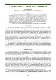
The microstructure (Fig. 1) <strong>of</strong> heat resistant steels<br />
12Х1MФ and 15ХM1Ф looks like the one <strong>of</strong> the steel<br />
12Х1MФ that is presented <strong>in</strong> the work [1]. Here also<br />
carbide “cha<strong>in</strong>s” (dark thicker fields) – coagulated carbides<br />
are clearly seen along the boundaries <strong>of</strong> the gra<strong>in</strong>s.<br />
Different is only the weld<strong>in</strong>g seam steel (Fig. 1, e), which<br />
is f<strong>in</strong>e-gra<strong>in</strong>ed because <strong>of</strong> different thermal impact, but still<br />
relatively many carbide zones are seen.<br />
The clearest carbide cha<strong>in</strong>s are <strong>in</strong> the microstructure <strong>of</strong><br />
the steel 12Х1MФ, which was exploited for 1.51·10 5 h<br />
(Fig. 1, b). Although this is not the longest service time,<br />
but probably conditions <strong>of</strong> exploitation were severer.<br />
It was expected that <strong>in</strong> the microstructure <strong>of</strong> steel<br />
15Х1M1Ф (1.59·10 5 h) that was heat treated for 5 days at<br />
670 °C temperature and slowly cooled, would have clearly<br />
seen carbide “cha<strong>in</strong>s” (Fig. 1, f), but there were no differences<br />
from the microstructure <strong>of</strong> steels that were only <strong>in</strong><br />
exploitation. This means that dur<strong>in</strong>g the exploitation all<br />
carbon was bound to carbide precipitates.<br />
a<br />
c<br />
e<br />
Fig. 1. Optical microstructure <strong>of</strong> the steel etched by 4 % nital<br />
solution for 2 m<strong>in</strong>. – 3 m<strong>in</strong>.: a – 12Х1MФ (1.42·10 5 h),<br />
b – 12Х1MФ (1.51·10 5 h), c – 15Х1M1Ф (1.59·10 5 h)<br />
kept for 0.5 h at 1000 °C temperature and slowly cooled,<br />
d – 15Х1M1Ф (1.59·10 5 h), e – seam steel, f – 15Х1M1Ф<br />
(1.59·10 5 h) kept for 5 days at 670 °C temperature and<br />
slowly cooled. In brackets – service time <strong>of</strong> the steel<br />
In the steel 15Х1M1Ф (1.59·10 5 h) (Fig. 1, c), which<br />
was heat treated for 0.5 h at 1000 °C temperature and<br />
slowly cooled, carbide zones are also clearly seen.<br />
Probably, the time when the steel was kept at the certa<strong>in</strong><br />
temperature was too short and the carbide phases did not<br />
melt; or the cool<strong>in</strong>g was too slow, so carbide phase formed<br />
newly.<br />
b<br />
d<br />
f<br />
193
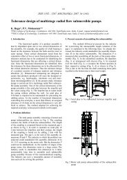
X-ray diffraction patterns (Fig. 2) <strong>of</strong> the samples, that<br />
were used <strong>in</strong> microscopic analysis, are quite similar, and<br />
all visible very sharp diffraction peaks, that have<br />
<strong>in</strong>terplanar spac<strong>in</strong>gs d (100) = 0.2027 nm; d (200) = 0.14336 nm<br />
and d (211) = 0.1171 nm, belong to ferrite (α-Fe) cubic<br />
lattice. There are no other diffraction peaks, also typical to<br />
carbide phase. This confirmed the literature data that<br />
carbide phase <strong>in</strong> the steel could be identifiable by <strong>XRD</strong><br />
only if there are 5 or more percents <strong>of</strong> it.<br />
α-Fe<br />
(110)<br />
Intensity, a. u.<br />
VC<br />
V 8 C 7<br />
M 6 Mo 6 C 2<br />
M 6 Mo 6 C 2<br />
M 6 Mo 6 C 2<br />
Cu<br />
(111)<br />
α−Fe<br />
(110)<br />
Cu<br />
(200)<br />
6<br />
5<br />
4<br />
Intensity, a. u.<br />
6<br />
5<br />
4<br />
3<br />
2<br />
1<br />
α-Fe<br />
(200)<br />
α-Fe<br />
(211)<br />
10 30 50 70 90<br />
Diffraction angle 2θ , deg.<br />
Fig. 2. X-ray diffraction patterns <strong>of</strong> the steel etched by 4 % nital<br />
solution for 2 m<strong>in</strong>.– 3 m<strong>in</strong>.: 1 – 12Х1MФ (1.51·10 5 h), 2 –<br />
seam steel 15Х1M1Ф (1.59·10 5 h), 3 – 12Х1MФ<br />
(1.42·10 5 h), 4 – 15Х1M1Ф (1.59·10 5 h), 5 – 15Х1M1Ф<br />
(1.59·10 5 h) kept for 0.5 h at 1000 °C temperature and<br />
slowly cooled, 6 – 15Х1M1Ф (1.59·10 5 h) kept for 5 days<br />
at 670 °C temperature and slowly cooled. In brackets –<br />
service time <strong>of</strong> the steel<br />
Therefore, <strong>in</strong> order to highlight the carbide phase, we<br />
tried various chemical and electrochemical etch<strong>in</strong>g<br />
methods.<br />
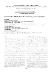
Etch<strong>in</strong>g the heat resistant steel <strong>in</strong> Marble solution was<br />
not effective to show up the carbide phase. After etch<strong>in</strong>g<br />
the steel 15Х1M1Ф (exploited for 1.59·10 5 h) for a short<br />
time (2 m<strong>in</strong>. – 3 m<strong>in</strong>.) only traces <strong>of</strong> carbide phase can be<br />
seen <strong>in</strong> <strong>XRD</strong> patterns (Fig. 3, curves 1 and 2), probably it<br />
is molybdenum carbide M 6 Mo 6 C 2 , where M can be any<br />
alloy<strong>in</strong>g element Cr, V, M, and Fe or comb<strong>in</strong>ation <strong>of</strong> them.<br />
Etch<strong>in</strong>g for a longer time (to 15 m<strong>in</strong>.) there was no<br />
<strong>in</strong>crease <strong>of</strong> the carbide phase diffraction peaks, and<br />
the surface <strong>of</strong> the sample encrusted with copper (Fig. 3,<br />
curve 6).<br />
Electrochemical polish<strong>in</strong>g for 30 m<strong>in</strong>utes <strong>in</strong> 5 %<br />
oxalic acid solution was not effective as well. No traces <strong>of</strong><br />
carbide phase diffraction peaks are seen <strong>in</strong> X-ray<br />
diffraction pattern (Fig. 3, curve 5).<br />
More effective appeared to be etch<strong>in</strong>g <strong>in</strong> 5 % NaCl<br />
solution (Fig. 3, curve 3) – here we can more clearly<br />
identify molybdenum carbide.<br />
30 35 40 45 50 55 60<br />
Diffraction angle 2θ , deg.<br />
Fig. 3. X-ray diffraction patterns <strong>of</strong> the steel 15Х1M1Ф<br />
(exploited for 1.59·10 5 h): 1 – the surface <strong>of</strong> the sample is<br />
polished 0.02 mm and etched for 2 m<strong>in</strong>. <strong>in</strong> Marble<br />
solution, 2 – polished 0.05 mm layer and etched for 3 m<strong>in</strong>.<br />
<strong>in</strong> Marble solution, 3 – the surface processed like the 2 nd<br />
sample and etched electrochemically for 10 m<strong>in</strong>. <strong>in</strong> 7 %<br />
NaCl + 0.5 % citric acid solution, 4 – the surface processed<br />
like the 3 rd sample and etched for 30 m<strong>in</strong>. <strong>in</strong> nital<br />
solution, 5 – the surface polished mechanically and for<br />
30 m<strong>in</strong>. polished electrochemically <strong>in</strong> 5 % oxalic acid<br />
solution, 6 – the surface polished mechanically and for<br />
15 m<strong>in</strong>. etched <strong>in</strong> Marble solution<br />
To set down a more effective etch<strong>in</strong>g regime we chose<br />
the steel У8. <strong>Carbide</strong> Fe 3 C – cementite is typical for this<br />
steel, and the amount <strong>of</strong> Fe 3 C <strong>in</strong> this steel is up 12 %, i.e.<br />
more than is needed to identify this phase by <strong>XRD</strong>.<br />
As electrochemical method <strong>of</strong> etch<strong>in</strong>g appeared to be<br />
the most effective, so, after try<strong>in</strong>g three etch<strong>in</strong>g solutions:<br />
7 % KCl + 0.5 % citric acid solution, 7 % NaCl + 0.5 %<br />
citric acid solution and 5 % HCl solution, we chose the<br />
latter, because by effectiveness it is as good as the<br />
recommended [15] 7 % KCl + 0.5 % citric acid solution<br />
and also it is cheaper and easier to prepare.<br />
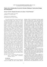
In diffraction patterns <strong>of</strong> the steel У8 we can clearly<br />
identify Fe 3 C peaks (Fig. 4, curve 4) after etch<strong>in</strong>g 90 s <strong>in</strong><br />
5 % HCl solution, and after 60 m<strong>in</strong>. etch<strong>in</strong>g ferrite<br />
diffraction maximum completely disappears (Fig. 4, curve<br />
8 and Fig. 5, curve 1).<br />
Fig. 5 shows the enlarged diffraction pattern <strong>of</strong> the<br />
steel У8 that was etched electrochemically for 1 hour <strong>in</strong><br />
5 % HCl solution (Fig. 5, curve 1), this pattern has almost<br />
no differences from the pattern <strong>of</strong> Fe 3 C standard, taken<br />
from PDF – 2 data base (Fig. 5, curve 2). So, for this<br />
particular steel electrochemical etch<strong>in</strong>g, which highlights<br />
carbide phase, is very effective.<br />
By apply<strong>in</strong>g previously mentioned electrochemical<br />
method <strong>of</strong> etch<strong>in</strong>g to highlight the carbide phase <strong>of</strong> heat<br />
resistant steels we got the results that are shown <strong>in</strong> Fig. 6.<br />
3<br />
2<br />
1<br />
194
Intensity a. u.<br />
α-Fe<br />
(110)<br />
-Fe 3 C<br />
35 45 55 65<br />
Diffracion angle 2θ , deg.<br />
α-Fe<br />
(200)<br />
Fig. 4. X-ray diffraction patterns <strong>of</strong> the steel У8. Surface<br />
mechanically polished – 1; electrochemically etched <strong>in</strong><br />
5 % HCl solution: 15 s – 2; 45 s – 3; 90 s – 4; 3 m<strong>in</strong>. – 5;<br />
5 m<strong>in</strong>. – 6; 15 m<strong>in</strong>. – 7; 1 h – 8<br />
Intensity, a. u.<br />
Fe 3 C<br />
(121)<br />
(210)<br />
Fe 3 C<br />
(002)<br />
Fe 3 C<br />
(201)<br />
(220)<br />
Fe 3 C<br />
(102)<br />
Fe 3 C<br />
(211)<br />
Fe 3 C<br />
(031)<br />
Fe 3 C<br />
(112)<br />
Fe 3 C<br />
(022)<br />
(131)<br />
Fe 3 C<br />
(221)<br />
35 40 45 50 55<br />
Diffraction angle 2θ , deg.<br />
2<br />
1<br />
8<br />
7<br />
6<br />
5<br />
4<br />
3<br />
2<br />
1<br />
Fe 3 C Fe 3 C<br />
(122) (230)<br />
Fig. 5. X-ray diffraction pattern <strong>of</strong> the steel У8 etched<br />
electrochemically for 1 hours <strong>in</strong> 5 % HCl solution – 1 and<br />
Fe 3 C standard diffraction curve taken from PDF-2 data<br />
base – 2<br />
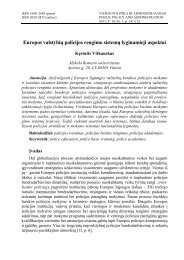
Differently from optical microanalysis, here we can<br />
clearly identify carbide phases and distribution <strong>of</strong> alloy<strong>in</strong>g<br />
elements <strong>in</strong> various carbide compounds depend<strong>in</strong>g on<br />
different exploitation and thermal regimes.<br />
We can see that steel 12Х1MФ exploited for 1.42·10 5<br />
hours (Fig. 6, curve 1) preserved the <strong>in</strong>itial steel structure<br />
best <strong>of</strong> all, i.e. here appeared relatively <strong>in</strong>tensive<br />
diffraction peaks <strong>of</strong> cementite (Fe 3 C), diffraction peaks <strong>of</strong><br />
vanadium carbide (VC, V 8 C 7 ) and molybdenum carbide<br />
(Mo 2 C) are not sharp, and diffraction peaks’ <strong>in</strong>tensity <strong>of</strong><br />
the carbide phase (M 23 C 6 ) formed from other alloy<strong>in</strong>g<br />
elements is even lesser, where M stands for a mixture <strong>of</strong><br />
iron and substitutional solute atoms (Cr, V, Mo).<br />
If compared to above-mentioned steel, <strong>in</strong> steel<br />
12Х1MФ, that was exploited for 1.51·10 5 h (Fig. 6, curve<br />
2), the amount <strong>of</strong> cementite decreased more than twice<br />
(identified by peaks’ <strong>in</strong>tensity), diffraction peaks <strong>of</strong> VC,<br />
V 8 C 7 and Mo 2 C <strong>in</strong>creased, also chromium carbide (Cr 7 C 3 )<br />
and special chromium carbide (Cr, Fe) 7 C 3 , that has got<br />
iron, diffraction peaks appeared.<br />
In diffraction pattern <strong>of</strong> steel 15Х1M1Ф, exploited for<br />
1.59·10 5 hours (Fig. 6, curve 4), differently from abovementioned<br />
steels, <strong>in</strong>tensive molybdenum carbide<br />
(M 6 MoC 2 ) diffraction maximums can be seen. Here M –<br />
alloy<strong>in</strong>g element. PDF-2 data base gives compound<br />
Co 6 MoC 2 (cubic lattice, space group Fd3m No. 227),<br />
which <strong>in</strong>terplanar spac<strong>in</strong>gs d hkl best suit our recorded<br />
pattern, only slightly biased. It means that the found<br />
compound’s lattice parameters have only a slight<br />
difference, and <strong>in</strong>stead <strong>of</strong> Co here is another element, and<br />
there is no Co <strong>in</strong> this steel. Another compound’s –<br />
Fe 3 Mo 3 C – lattice parameters are also very close to our<br />
<strong>in</strong>vestigated steel’s carbide phase, but here the difference is<br />
bigger than with Co 6 MoC 2 . This means that no data <strong>in</strong><br />
PDF-2 data base were found about the compound that<br />
formed <strong>in</strong> our case.<br />
The most <strong>in</strong>tensive peaks <strong>of</strong> carbide phase can be seen<br />
<strong>in</strong> seam steel diffraction pattern (Fig. 6, curve 5). Here VC,<br />
V 8 C 7 diffraction peaks <strong>in</strong>tensities are approximately equal<br />
to those <strong>of</strong> steel 12Х1MФ (1.51·10 5 h) (Fig. 6, curve 2),<br />
but very <strong>in</strong>tensive peaks <strong>of</strong> M 6 MoC 2 appeared and some<br />
sharp diffraction peaks rema<strong>in</strong>ed unidentified. They could<br />
be attributed to boron carbides BC 4 , B 13 Cr (Mo, M) C, but<br />
additional elemental exam<strong>in</strong>ation <strong>of</strong> composition would be<br />
needed for more precise analysis.<br />
By the way, seam steel’s phase composition and the<br />
amount <strong>of</strong> carbides (Fig. 6, curve 5) looks very similar to<br />
steel 15Х1M1Ф, that was exploited for 1.59·10 5 h, kept for<br />
5 days at 675 °C temperature and slowly cooled (Fig. 6,<br />
curve 6). In <strong>XRD</strong> patterns <strong>of</strong> them <strong>in</strong>tensity <strong>of</strong> diffraction<br />
peaks <strong>of</strong> the carbides M 6 MoC 2 and (Cr, Fe) 7 C 3 are almost<br />
the same, and VC, V 8 C 7 – bigger <strong>in</strong> the steel that was<br />
affected by high temperature. Furthermore, <strong>in</strong> the lastmentioned<br />
steel’s diffraction pattern the very <strong>in</strong>tensive<br />
peaks <strong>of</strong> carbide M 23 C are visible. So, by affect<strong>in</strong>g steel <strong>in</strong><br />
this way, the process <strong>of</strong> carbide form<strong>in</strong>g and their<br />
coagulation is stimulated.<br />
In <strong>XRD</strong> pattern <strong>of</strong> the steel 15Х1M1Ф, which was exploited<br />
for 158·10 5 h, kept for 0.5 h at 1000 °C temperature<br />
and slowly cooled (Fig. 6, curve 3) very <strong>in</strong>tensive VC,<br />
V 8 C 7 peaks are seen, the peaks <strong>of</strong> other carbides are hardly<br />
seen or totally vanished. It means that even <strong>in</strong> such<br />
temperature carbides had to melt, but slow cool<strong>in</strong>g enabled<br />
form<strong>in</strong>g <strong>of</strong> thermodynamically most stable carbides.<br />
195
α-Fe<br />
M 23<br />
C 6<br />
M 6<br />
Mo 6<br />
C 2<br />
M 6<br />
Mo 6<br />
C 2<br />
Cr 7<br />
C 3<br />
Fe 3<br />
C<br />
Fe 3<br />
C (Cr,Fe) 7<br />
C 3<br />
Fe 3<br />
C Fe<br />
VC<br />
3<br />
C<br />
VC<br />
V 8<br />
C 7<br />
Fe 3<br />
C<br />
V 8<br />
C Mo 7 2<br />
C<br />
M 6<br />
Mo 6<br />
C 2 (Cr,Fe)<br />
M 23<br />
C Fe 3<br />
C<br />
7<br />
C 3<br />
6<br />
M 6<br />
Mo 6<br />
C 2<br />
M 23<br />
C<br />
Fe 6<br />
3<br />
C<br />
Mo<br />
M 6<br />
Mo 6<br />
C 2<br />
M 6<br />
Mo 6<br />
C<br />
2<br />
C<br />
(Cr,Fe) M 23<br />
C 6 M 23<br />
C 7<br />
C 3 6<br />
Fe 3<br />
C M 23<br />
C (Cr,Fe)<br />
Fe 7<br />
C<br />
<br />
3<br />
3<br />
C<br />
<br />
Fe 3<br />
C<br />
Mo 2<br />
C<br />
Fe 3<br />
C<br />
<br />
Intensity a. u.<br />
6<br />
5<br />
4<br />
3<br />
2<br />
1<br />
30 35 40 45 50 55<br />
Diffraction angle 2θ , deg.<br />
Fig. 6. X-ray diffraction patterns <strong>of</strong> heat resistant steel etched electrochemically for 105 m<strong>in</strong>. <strong>in</strong> 5 % HCl solution: 1 – steam pipel<strong>in</strong>e<br />
steel 12Х1MФ exploited for 1.42·10 5 h, 2 – steam pipel<strong>in</strong>e steel 12Х1MФ exploited for 1.51·10 5 h, 3 – ma<strong>in</strong> steam collector’s<br />
steel 15Х1M1Ф exploited for 1.59·10 5 h, kept for 30 m<strong>in</strong>. at 1000 °C temperature and slowly cooled, 4 – 15Х1M1Ф steel<br />
exploited for 1.59·10 5 h, 5 – weld<strong>in</strong>g seam steel, 6 – steel 15Х1M1Ф exploited for 1.59·10 5 h, kept for 5 days at 675 °C<br />
temperature and slowly cooled<br />
Dur<strong>in</strong>g the service exposure mostly aged ma<strong>in</strong> steam<br />
collector’s steel 15Х1M1Ф exploited for 1.51·10 5 h was<br />
chosen to show the possibility to do the reconstruction <strong>of</strong><br />
steel crystall<strong>in</strong>e structure for the power plant components’<br />
life extension. For this reason steel was heat treated for<br />
0.5 h at 1000 °C and quickly cooled <strong>in</strong> water, after that it<br />
was heat treated for 5 h at 400, 500, 600 and 700 °C and<br />
quickly cooled <strong>in</strong> air to room temperature. Their diffraction<br />
patterns after electrochemical etch<strong>in</strong>g <strong>in</strong> 5 % HCl are<br />
shown <strong>in</strong> Fig. 7.<br />
An as-quenched structure <strong>of</strong> 15Х1M1Ф steel consists<br />
<strong>of</strong> martensite and austenite (Fig. 7, curve 1), and carbide<br />
phase is dissolved (no diffraction peaks).<br />
After temper<strong>in</strong>g <strong>in</strong> above-mentioned four stages the<br />
martensite loses tetragonality, austenite decomposes and<br />
carbide phase forms <strong>in</strong> steel crystall<strong>in</strong>e structure (Fig. 7,<br />
curves 2 – 5).<br />
Dur<strong>in</strong>g the heat treatment <strong>of</strong> steel at 400 °C, the<br />
cementite diffraction peaks appear <strong>in</strong> diffraction pattern<br />
(Fig. 7 curve 2).<br />
196
α -Fe<br />
Mo 2 C<br />
V 8 C 7<br />
Fe 3 C V<br />
Fe 3 C<br />
8 C 7<br />
Fe 3 C<br />
Fe 3 C<br />
(Cr,Fe)<br />
Fe 3 C<br />
7 C 3<br />
(Cr,Fe) 7 C 3<br />
Fe 3 C<br />
Fe 3 C<br />
(Cr,Fe) 7 C 3<br />
(Cr,Fe) 7 C 3<br />
Fe 3 C<br />
Fe 3 C<br />
Fe 3 C<br />
5<br />
Intensity, a. u.<br />
4<br />
3<br />
2<br />
1<br />
Austenite<br />
Martensite<br />
Austenite<br />
30 35 40 45 50 55<br />
Diffraction angle 2θ , deg.<br />
Fig. 7. X-ray diffraction patterns <strong>of</strong> steel 15Х1M1Ф exploited for 1.59·10 5 kept for 0.5 h at 1000 °C, water – cooled to the room<br />
temperature – 1 and regenerative heat treated for 5 h at: 400 °C – 2, 500 °C – 3, 600 °C – 4 and 700 °C – 5<br />
After temper<strong>in</strong>g <strong>of</strong> steel at 700 °C, the thermodynamically<br />
more stable than cementite carbides (V 8 C 7 , (Cr,<br />
Fe) 7 C3) already formed (Fig. 7, curve 5).<br />
Diffraction pattern 3 <strong>in</strong> Fig. 7 shows the most perfect<br />
crystall<strong>in</strong>e structure <strong>of</strong> cementite that allows to determ<strong>in</strong>e<br />
the most suitable temperature – 500 °C for regenerative<br />
heat treatment <strong>of</strong> aged 15Х1M1Ф steel. However, <strong>in</strong> order<br />
to produce a stable microstructure <strong>of</strong> steel the higher<br />
regenerative heat treatment temperature is required,<br />
because temper<strong>in</strong>g at a higher temperature than service<br />
temperature gives better long-term creep properties [2]. In<br />
this case for 15Х1M1Ф steel, temper<strong>in</strong>g at a temperature<br />
<strong>of</strong> approximately 600 °C would be preferable.<br />
CONCLUSIONS<br />
Electrochemical etch<strong>in</strong>g <strong>in</strong> 5 % HCl solution <strong>of</strong> low<br />
alloy power plant steels is an effective procedure to<br />
selectively extract carbide phase precipitates from steel<br />
matrix for <strong>XRD</strong> analysis.<br />
Optical microscopy does not enable clearly dist<strong>in</strong>guish<br />
the state <strong>of</strong> carbide phase precipitation.<br />
Differently from the optical microscopy, the <strong>XRD</strong><br />
technique enables to study properly the matrix and the<br />
various types <strong>of</strong> carbide precipitates formed at different<br />
heat treatment temperatures <strong>in</strong> both bulk specimens and<br />
selectively extracted samples. The important factor <strong>of</strong><br />
steel’s obsolescence and features change is alloy<strong>in</strong>g<br />
elements’ diffusion from ferrite <strong>in</strong>to the boundaries <strong>of</strong><br />
matrix gra<strong>in</strong>s and the precipitat<strong>in</strong>g <strong>of</strong> the carbide phase.<br />
This factor can be measured by identify<strong>in</strong>g carbide phases<br />
from X-ray diffraction patterns and the <strong>in</strong>tensity <strong>of</strong> those<br />
peaks def<strong>in</strong>es the amount <strong>of</strong> the carbide phases.<br />
The accomplished <strong>XRD</strong> analysis <strong>of</strong> the carbide phase<br />
<strong>in</strong> heat resistant steels allows to state that only steel<br />
12Х1MФ exploited for 1.42·10 5 h (Fig. 6, curve 1) and<br />
partly steel 12Х1MФ exploited for 1.51·10 5 h (Fig. 6,<br />
curve 2) meet the requirements <strong>of</strong> exploitation structure.<br />
Talk<strong>in</strong>g about the rest steels, the regenerative heat treatment<br />
should be projected follow<strong>in</strong>g the recommendations<br />
given <strong>in</strong> literature [16, 17].<br />
For life extension <strong>of</strong> power plant components made<br />
from steel 15Х1M1Ф the most suitable restoration<br />
procedure <strong>of</strong> crystall<strong>in</strong>e structure and properties <strong>of</strong> steel is<br />
197
heat treatment at 1000 °C, quench<strong>in</strong>g and temper<strong>in</strong>g at<br />
600 °C.<br />
Acknowledgments<br />
The f<strong>in</strong>ancial support from the Lithuanian State<br />
Science and Study Foundation for the research and the<br />
participation <strong>in</strong> the activity <strong>of</strong> COST Action 538 “High<br />
temperature plant lifetime extension” and carry<strong>in</strong>g out<br />
National project “X-ray diffraction analysis <strong>of</strong> carbide<br />
phase <strong>in</strong> heat resistant steels“ is greatly appreciated.<br />
REFERENCES<br />
1. Rudz<strong>in</strong>skas, V., Valiulis, A. V., Černašėjus, O., Višniakov,<br />
N. Dynamics <strong>of</strong> Properties and Structure Changes <strong>of</strong> Pearlite<br />
Steel dur<strong>in</strong>g Long-lived Operation Materials Science<br />
(Medžiagotyra) 9 (2) 2003: pp. 164 – 168.<br />
2. Masuyama, F. History <strong>of</strong> Power Plants and Progress <strong>in</strong> <strong>Heat</strong><br />
<strong>Resistant</strong> Steles ISIJ International 41 (6) 2001:<br />
pp. 612 – 625.<br />
3. Bhadeshia, H. K. D. H. Design <strong>of</strong> Ferritic Creep-resistant<br />
<strong>Steels</strong> ISIJ International 41 (6) 2001: pp. 626 – 640.<br />
4. Robson, J. D., Bhadeshia, H. K. D. H. K<strong>in</strong>etics <strong>of</strong><br />
Precipitation <strong>in</strong> Power Plant <strong>Steels</strong> Calphad 20 (4) 1996:<br />
pp. 447 – 460.<br />
5. Fujita, N., Bhadeshia, H. K. D. H. Model<strong>in</strong>g Simultaneous<br />
Alloy <strong>Carbide</strong> Sequence <strong>in</strong> Power Plant Steles ISIJ<br />
International 42 (7) 2002: pp. 760 – 769.<br />
6. Thomson, R.C. and Bhadeshia, H. K. D. H. Changes <strong>in</strong><br />
Chemical Composition <strong>of</strong> <strong>Carbide</strong>s <strong>in</strong> 2.25Cr-1Mo Power<br />
Plant Steel. Part 1 Ba<strong>in</strong>itic Microstructure Materials<br />
Science and Technology 10 1994: pp. 193 – 203.<br />
7. Islam, M. A., Knott, J. F., Bowen, P. K<strong>in</strong>etics <strong>of</strong><br />
Phosphorus Segregation and Its Effect on Low Temperature<br />
Fracture Behaviour <strong>in</strong> 2.25Cr–1Mo Pressure Vessel Steel<br />
Materials Science and Technology 2 (1) 2005, pp. 76 – 84.<br />
8. Robson, J. D., Bhadeshia, H. K. D. H. Modell<strong>in</strong>g<br />
Precipitation Sequences <strong>in</strong> Power Plant <strong>Steels</strong>. Part 2 –<br />
Application <strong>of</strong> K<strong>in</strong>etic Theory Materials Science and<br />
Technology 13 1997: pp. 640 – 644.<br />
9. Mitchell, D. R. G., Small, R. Microstructural Evolution <strong>in</strong><br />
Seven 2.25Cr–1Mo Superheater Outlet Headers Result<strong>in</strong>g<br />
from Service Exposure Science and Technology <strong>of</strong><br />
Weld<strong>in</strong>g and Jo<strong>in</strong><strong>in</strong>g 6 (3) 2001: pp 168 – 175.<br />
10. Mitchell, D. R. G., Ball, C. J. A Quantitative X-ray Diffraction<br />
and Analytical Electron Microscopy Study <strong>of</strong> Serviceexposed<br />
2.25Cr-1Mo <strong>Steels</strong> Materials Characterization<br />
47 2001: pp. 17 – 26.<br />
11. Zheng-Fei, H., Zhen-Guo, Y. An Investigation <strong>of</strong> the<br />
Embrittlement <strong>in</strong> X20CrMoV12.1 Power Plant Steel after<br />
Long-term Service Exposure at Elevated Temperature<br />
Materials Science and Eng<strong>in</strong>eer<strong>in</strong>g A 383 2004:<br />
pp. 224 – 228.<br />
12. Miyata, K., Omura, T., Kushida, T., Komizo, Y.<br />
Coarsen<strong>in</strong>g K<strong>in</strong>etics <strong>of</strong> Multicomponent MC-Type <strong>Carbide</strong>s<br />
<strong>in</strong> High-Strength Low-Alloy <strong>Steels</strong> Metallurgical and<br />
Materials Transactions A 34 A 2003: pp. 1565 – 1573.<br />
13. Jayana, V., Khanb, M.Y., Husa<strong>in</strong>, M. Coarsen<strong>in</strong>g <strong>of</strong> Nano<br />
Sized <strong>Carbide</strong> Particles <strong>in</strong> 2.25Cr–1Mo Power Plant Steel<br />
after Extended Service Materials Letters 58 2004:<br />
pp. 2569 – 2573.<br />
14. PDF-2 International Centre for Diffraction Data,12 Campus<br />
Boulevard Newtown Square, PA 19073–3273 USA.<br />
15. Gorelik, S. S., Rastorguev, L. N., Skakov, U. A. X-ray<br />
Diffraction and Electron Optical <strong>Analysis</strong>. Metalurgija,<br />
Moscow, 1970 (<strong>in</strong> Russian).<br />
16. Trusov, L. P., Bogatyrev, U. M., Erem<strong>in</strong>a, V. P.,<br />
Uporova, V. A., Ashixm<strong>in</strong>a, L. A., Lepex<strong>in</strong>, A. Z.<br />
Restoration <strong>of</strong> Microstructure and Properties <strong>of</strong> 12Ch1MF<br />
Steel after Long-term Service Exposure Teploenergetika<br />
1 (3) 1976: pp. 69 – 71 (<strong>in</strong> Russian).<br />
17. Zisl<strong>in</strong>, G. S., Kamenskaja, N. I., Shabal, V. N.,<br />
Еmeljanov, V. А., Pirogov, U. Т. Regenerative <strong>Heat</strong><br />
Treatment <strong>of</strong> Ma<strong>in</strong> Steam Pipel<strong>in</strong>e Tube on Cherepetsk<br />
Power Plant Welder 4 2002: (<strong>in</strong> Russian).<br />
198