EE 448 Fall 2006 Lab Experiment No. 1 Single Phase AC Circuits
EE 448 Fall 2006 Lab Experiment No. 1 Single Phase AC Circuits
EE 448 Fall 2006 Lab Experiment No. 1 Single Phase AC Circuits

Create successful ePaper yourself
Turn your PDF publications into a flip-book with our unique Google optimized e-Paper software.
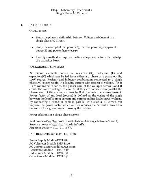
<strong>EE</strong> <strong>448</strong> <strong>Lab</strong>oratory <strong>Experiment</strong> 1<br />
<strong>Single</strong> <strong>Phase</strong> <strong>AC</strong> <strong>Circuits</strong><br />
I. INTRODUCTION<br />
OBJECTIVES:<br />
• Study the phasor relationship between Voltage and Current in a<br />
single phase <strong>AC</strong> Circuit.<br />
• Study the concept of real power (P), reactive power (Q), apparent<br />
power(S) and power factor (cosΦ).<br />
• Identify a method to improve the line side power factor with the help<br />
of a capacitor bank.<br />
B<strong>AC</strong>KGROUND SUMMARY:<br />
<strong>AC</strong> circuit elements consist of resistors (R), inductors (L) and<br />
capacitors(C) which can be fed from either a 3 phase or 1 phase 60 Hz,<br />
120V source. Resistor and inductor combination connected to a single<br />
phase <strong>AC</strong> source results in a lagging current with respect to voltage. If R &<br />
L are connected in series, the phasor sum of the voltages across L and R<br />
equals the source voltage. In contrast if they are connected in parallel the<br />
phasor sum of the currents drawn by R & L equals the source current.<br />
Power factor of any load (source) is defined as the cosine of the angle<br />
between the load(source) current and corresponding load(source) voltage.<br />
By connecting a capacitor bank in parallel with such a RL circuit can<br />
improve the power factor which in turn reduces the current drawn from<br />
the source for a given power drawn by the resistor.<br />
Power relations in a single phase system<br />
Real power =V rms *I rms cosΦ in watts (where Φ is angle between V and I)<br />
Reactive power = V rms *I rms * sin(Φ) in VARs<br />
Apparent power = V rms *I rms in VA<br />
INSTRUMENTS and COMPONENTS:<br />
Power Supply Module EMS 8821<br />
<strong>AC</strong> Voltmeter Module EMS 8426<br />
<strong>AC</strong> Current Meter ModuleEM.S 8428<br />
Resistance Module EMS 8311<br />
Inductance Module EMS 8321<br />
Capacitance Module EMS 8421<br />
2