EE 448 Fall 2006 Lab Experiment No. 1 Single Phase AC Circuits
EE 448 Fall 2006 Lab Experiment No. 1 Single Phase AC Circuits
EE 448 Fall 2006 Lab Experiment No. 1 Single Phase AC Circuits

You also want an ePaper? Increase the reach of your titles
YUMPU automatically turns print PDFs into web optimized ePapers that Google loves.
<strong>EE</strong> <strong>448</strong> <strong>Lab</strong>oratory <strong>Experiment</strong> 1<br />
<strong>Single</strong> <strong>Phase</strong> <strong>AC</strong> <strong>Circuits</strong><br />
2. Observe the voltage waveforms of V s and V r on the oscilloscope and<br />
identify the phase difference between these two voltages.<br />
3. Disconnect only the inductor and measure the phase difference between<br />
V s and V r .<br />
4. <strong>No</strong>w reconnect the inductor, remove the resistor and measure the phase<br />
difference between V s and V 1 . Does the data from the previous steps<br />
match your calculations for step 4 of part II<br />
5. Connect the circuit as shown in Figure 5.<br />
6. Measure the currents A s , A r and A 1 .<br />
a. Does the data from steps e and f match your calculations from<br />
step 5 of part II<br />
7. Calculate the power delivered to the circuit.<br />
8. Calculate the p.f. of the load.<br />
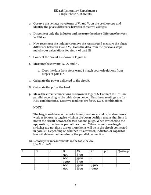
9. Make the circuit connections as shown in Figure 6. Connect R, L & C in<br />
parallel according to the table given below. First three readings are for<br />
R&L combinations. Last two readings are for R, L & C combinations.<br />
NOTE:<br />
The toggle switches on the inductance, resistance, and capacitive boxes<br />
work as follows. A toggle switch in the down position means that item is<br />
not in the circuit between the two banana plugs. When switched to the<br />
up position, the item is part of the circuit. When two or more toggle<br />
switches are up, those two or more items will be in the circuit connected<br />
in parallel. Depending on whether it’s a resistor, inductor, or capacitor<br />
box will determine the value of the parallel connection.<br />
10. Record your measurements in the table below.<br />
Use V = 120V<br />
I S P R Xi Xc p.f. Q=sin φ<br />
300 j300 -<br />
600 j300 -<br />
1200 j300 -<br />
600 j300 -j300<br />
600 j600 -j300<br />
5