EE 448 Fall 2006 Lab Experiment No. 1 Single Phase AC Circuits
EE 448 Fall 2006 Lab Experiment No. 1 Single Phase AC Circuits
EE 448 Fall 2006 Lab Experiment No. 1 Single Phase AC Circuits

Create successful ePaper yourself
Turn your PDF publications into a flip-book with our unique Google optimized e-Paper software.
<strong>EE</strong> <strong>448</strong> <strong>Lab</strong>oratory <strong>Experiment</strong> 1<br />
<strong>Single</strong> <strong>Phase</strong> <strong>AC</strong> <strong>Circuits</strong><br />
II.<br />
Pre-<strong>Lab</strong> Test Questions and Calculations<br />
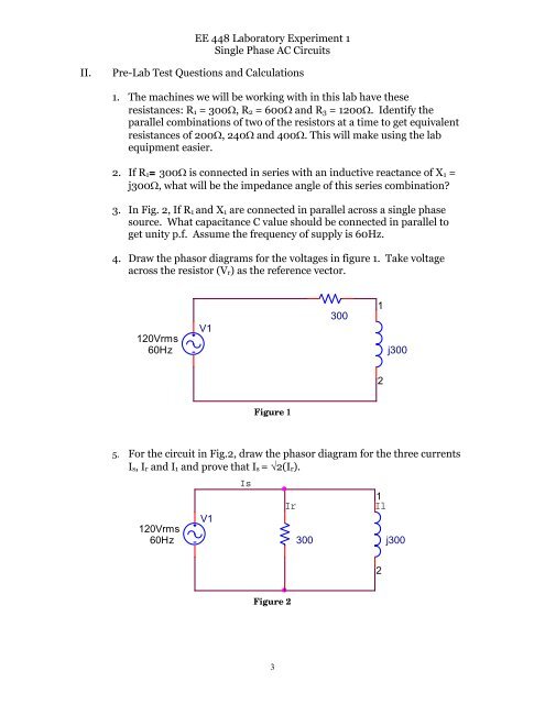
1. The machines we will be working with in this lab have these<br />
resistances: R 1 = 300Ω, R 2 = 600Ω and R 3 = 1200Ω. Identify the<br />
parallel combinations of two of the resistors at a time to get equivalent<br />
resistances of 200Ω, 240Ω and 400Ω. This will make using the lab<br />
equipment easier.<br />
2. If R 1 = 300Ω is connected in series with an inductive reactance of X 1 =<br />
j300Ω, what will be the impedance angle of this series combination<br />
3. In Fig. 2, If R 1 and X 1 are connected in parallel across a single phase<br />
source. What capacitance C value should be connected in parallel to<br />
get unity p.f. Assume the frequency of supply is 60Hz.<br />
4. Draw the phasor diagrams for the voltages in figure 1. Take voltage<br />
across the resistor (V r ) as the reference vector.<br />
120Vrms<br />
60Hz<br />
V1<br />
300<br />
1<br />
j300<br />
2<br />
Figure 1<br />
5. For the circuit in Fig.2, draw the phasor diagram for the three currents<br />
I s , I r and I 1 and prove that I s = √2(I r ).<br />
120Vrms<br />
60Hz<br />
V1<br />
Is<br />
Ir<br />
300<br />
1<br />
Il<br />
j300<br />
2<br />
Figure 2<br />
3