Product Specifications - Amana HAC
Product Specifications - Amana HAC
Product Specifications - Amana HAC

Create successful ePaper yourself
Turn your PDF publications into a flip-book with our unique Google optimized e-Paper software.
®<br />
®<br />
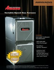
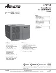
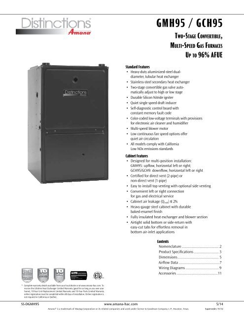
GMH95 / GCH95<br />
Two-Stage Convertible,<br />
Multi-Speed Gas Furnaces<br />
Up to 96% AFUE<br />
Standard Features<br />
• Heavy-duty aluminized-steel dualdiameter,<br />
tubular heat exchanger<br />
• Stainless-steel secondary heat exchanger<br />
• Two-stage convertible gas valve automatically<br />
adjust to high or low stage<br />
• Durable Silicon Nitride igniter<br />
• Quiet single speed draft inducer<br />
• Self-diagnostic control board with<br />
constant memory fault code<br />
• Color-coded low-voltage terminals with provisions<br />
for electronic air cleaner and humidifier<br />
• Multi-speed blower motor<br />
• Low continuous fan speed options offer<br />
quiet air circulation<br />
• All models comply with California<br />
Low NOx emissions standards<br />
Cabinet Features<br />
• Designed for multi-position installation:<br />
GMH95: upflow, horizontal left or right;<br />
GCH95/GCH9: downflow, horizontal left or right<br />
• Certified for direct vent (2-pipe) or<br />
non-direct vent (1-pipe)<br />
• Easy to install top venting with optional side venting<br />
• Convenient left or right connection<br />
for gas and electrical service<br />
• Cabinet air leakage (Q Leak ) ≤ 2%<br />
• Heavy-gauge steel cabinet with durable<br />
baked-enamel finish<br />
• Fully insulated heat exchanger and blower section<br />
• Airtight solid bottom or side-return with<br />
easy-cut tabs for effortless removal in<br />
bottom air-inlet applications<br />
Contents<br />
Nomenclature........................................ 2<br />
<strong>Product</strong> <strong>Specifications</strong>........................... 3<br />
Dimensions............................................ 5<br />
Airflow Data............................................7<br />
Wiring Diagrams.................................... 9<br />
Accessories............................................11<br />
* Complete warranty details available from your local dealer or at www.amana-hac.com. To<br />
receive the Lifetime Heat Exchanger Limited Warranty (good for as long as you own your<br />
home), 10-Year Unit Replacement Limited Warranty and 10-Year Parts Limited Warranty,<br />
online registration must be completed within 60 days of installation. Online registration is<br />
not required in California or Québec.<br />
SS-DGMH95 www.amana-hac.com 5/14<br />
<strong>Amana</strong>® is a trademark of Maytag Corporation or its related companies and used under license to Goodman Company, L.P., Houston, Texas. Supersedes 11/12
<strong>Product</strong> <strong>Specifications</strong><br />
Nomenclature<br />
G<br />
M<br />
H<br />
95 045<br />
4<br />
B<br />
X<br />
A<br />
1<br />
2<br />
3<br />
4,5<br />
6,7,8<br />
9<br />
10<br />
11<br />
12<br />
Brand<br />
Revisions<br />
G Goodman ® Brand A Initial Release<br />
or Distinctions B 1st Revision<br />
C 2nd Revision<br />
Airflow Direction<br />
C Downflow/Horizontal NOx<br />
D Dedicated Downflow N Natural Gas<br />
H High Airflow X Low NOx<br />
K Dedicated Upflow<br />
M Upflow/Horizontal Cabinet Width<br />
A 14”<br />
Description B 17½”<br />
V Two-Stage/Variable-speed C 21”<br />
H Two-Stage/Multi-speed D 24½”<br />
S Single-Stage/Multi-speed<br />
E Two-Stage/EEM Motor Maximum CFM @ 0.5” ESP<br />
3 1200 5 2000<br />
AFUE 4 1600<br />
95 95%<br />
9 93%+ MBTU/h<br />
8 80% 045: 45,000 115: 115,000<br />
070: 70,000 140: 140,000<br />
090: 90,000<br />
2 www.amana-hac.com SS-DGMH95
<strong>Product</strong> <strong>Specifications</strong><br />
<strong>Specifications</strong> for GMH95<br />
Heating Capacity<br />
GMH95<br />
0453BXA<br />
GMH95<br />
0703BXA<br />
GMH95<br />
0704CXA<br />
GMH95<br />
0904CXA<br />
GMH95<br />
0905CXA<br />
GMH95<br />
1155DXA<br />
Input¹ 46,000 69,000 69,000 92,000 92,000 115,000<br />
Natural Gas Output¹ 44,200 66,300 66,300 88,400 88,400 110,500<br />
LP Gas Output¹ 39,800 59,700 59,700 79,600 79,600 99,500<br />
AFUE² 96.1 96.1 96.1 96.1 96.1 96.1<br />
Available AC @ 0.5” ESP 3 3 4 4 5 5<br />
Temperature Rise Range (°F) 35 - 65 30 - 60 35 - 65 30 - 60 30 - 60 35 - 65<br />
Circulator Blower<br />
Size (D x W) 10” x 8” 10” x 8” 10” x 10” 10” x 10” 11” x 10” 11” x 10”<br />
Horsepower @ 1075 RPM ⅓ ⅓ ½ ½ ¾ ¾<br />
Speed 4 4 4 4 4 4<br />
Vent Diameter³ 2” 2” 2” 2” 3” 3”<br />
No. of Burners 2 3 3 4 4 5<br />
Filter Size (in²)<br />
Permanent⁴ 290 288 385 385 480 480<br />
Disposable 580 580 770 770 960 960<br />
Electrical Data<br />
Min. Circuit Ampacity⁵ 9.4 9.4 13.8 13.8 13.2 13.2<br />
Max. Overcurrent Device (amps)⁶ 15 15 15 15 15 15<br />
Ship Weight (lbs) 120 123 125 144 146 163<br />
¹ Natural Gas BTU/h. For altitudes above 2,000’, reduce input rating 4% for each 1,000’ above sea level.<br />
² DOE AFUE based upon Isolated Combustion System (ICS)<br />
³ Installer must supply one or two PVC pipes: one for combustion air (optional) and one for the flue outlet (required). Vent pipe<br />
must be either 2” or 3” in diameter, depending upon furnace input, number of elbows, length of run and installation (1 or 2<br />
pipes). The optional Combustion Air Pipe is dependent on installation/code requirements and must be 2” or 3” diameter PVC.<br />
⁴ Minimum Circuit Ampacity = (1.25 x Circulator Blower Amps) + ID Blower amps. Wire size should be determined<br />
in accordance with National Electrical Codes. Extensive wire runs will require larger wire sizes.<br />
⁵ Maximum Overcurrent Protection Device refers to maximum recommended fuse or circuit breaker<br />
size. May use fuses or <strong>HAC</strong>R-type circuit breakers of the same size as noted.<br />
Notes<br />
• All furnaces are manufactured for use on 115 VAC, 60 Hz, single-phase electrical supply.<br />
• Gas Service Connection ½” FPT<br />
• Important: Size fuses and wires properly and make electrical connections in accordance with the National Electrical Code and/or<br />
all existing local codes.<br />
SS-DGMH95 www.amana-hac.com 3
<strong>Product</strong> <strong>Specifications</strong><br />
<strong>Specifications</strong> for GCH95<br />
Heating Capacity<br />
GCH95<br />
0453BXA<br />
GCH95<br />
0703BXA<br />
GCH95<br />
0704CXA<br />
GCH95<br />
0904CXA<br />
GCH95<br />
0905DXA<br />
GCH93<br />
1155DXA<br />
Input¹ 46,000 69,000 69,000 92,000 92,000 115,000<br />
Natural Gas Output¹ 44,200 66,300 66,300 88,400 88,400 106,500<br />
LP Gas Output¹ 39,800 59,700 59,700 79,600 79,600 96,255<br />
AFUE² 96.1 96.1 96.1 96.1 96.1 93.0<br />
Available AC @ 0.5” ESP 3 3 4 4 5 5<br />
Temperature Rise Range (°F) 25-55 35-65 25-55 40 - 70 35-65 40 - 70<br />
Circulator Blower<br />
Size (D x W) 10” x 8” 10” x 8” 10” x 10” 10” x 10” 11” x 10” 11” x 10”<br />
Horsepower @ 1075 RPM ⅓ ⅓ ½ ½ ¾ ¾<br />
Speed 4 4 4 4 4 4<br />
Vent Diameter³ 2” 2” 2” 2” 2" 2"<br />
No. of Burners 2 3 3 4 4 5<br />
Disposable Filter Size (in²) 576 564 564 752 752 940<br />
Electrical Data<br />
Min. Circuit Ampacity⁴ 9.8 9.8 12.9 12.9 13.4 13.2<br />
Max. Overcurrent Device (amps)⁵ 15 15 15 15 15 15<br />
Ship Weight (lbs) 120 123 123 144 146 160<br />
¹ Natural Gas BTU/h. For altitudes above 2,000’, reduce input rating 4% for each 1,000’ above sea level.<br />
² DOE AFUE based upon Isolated Combustion System (ICS)<br />
³ Installer must supply one or two PVC pipes: one for combustion air (optional) and one for the flue outlet (required). Vent pipe<br />
must be either 2” or 3” in diameter, depending upon furnace input, number of elbows, length of run and installation (1 or 2<br />
pipes). The optional Combustion Air Pipe is dependent on installation/code requirements and must be 2” or 3” diameter PVC.<br />
⁴ Minimum Circuit Ampacity = (1.25 x Circulator Blower Amps) + ID Blower amps. Wire size should be determined<br />
in accordance with National Electrical Codes. Extensive wire runs will require larger wire sizes.<br />
⁵ Maximum Overcurrent Protection Device refers to maximum recommended fuse or circuit breaker<br />
size. May use fuses or <strong>HAC</strong>R-type circuit breakers of the same size as noted.<br />
Notes<br />
• All furnaces are manufactured for use on 115 VAC, 60 Hz, single-phase electrical supply.<br />
• Gas Service Connection ½” FPT<br />
• Important: Size fuses and wires properly and make electrical connections in accordance with the National Electrical Code and/or<br />
all existing local codes.<br />
4 www.amana-hac.com SS-DGMH95
<strong>Product</strong> <strong>Specifications</strong><br />
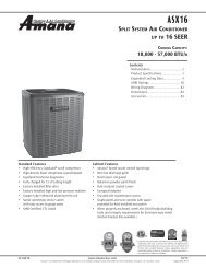
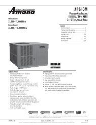
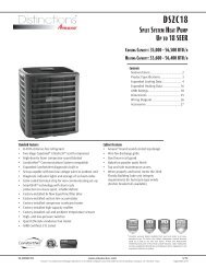
GMH95 Dimensions<br />
COMPONENT IDENTIFICATION<br />
GMH95*****XA*<br />
AIR<br />
DISCHARGE<br />
AIR<br />
DISCHARGE<br />
19 7/8”<br />
AIR<br />
INTAKE<br />
PIPE<br />
2" PVC<br />
1 1/2<br />
RIGHT SIDE<br />
DRAIN LINE<br />
HOLES<br />
2<br />
1 5/8<br />
1<br />
UNFOLDED FLANGES<br />
UNFOLDED FLANGES<br />
FOLDED FLANGES<br />
FOLDED FLANGES<br />
RIGHT SIDE VIEW<br />
Model A B C D E<br />
GMH950453BXA 17½” 16” 13⅛” 12⅛” 13⅝”<br />
GMH950703BXA 17½” 16” 13⅛” 12⅛” 13⅝”<br />
Cabinet Size A B C D E<br />
GMH950704CXA 21” 19½” 16⅛” 16” 17½”<br />
GMH950904CXA 21” 19½” 16⅛” 16” 17½”<br />
GMH950453BXA*<br />
17-1/2 16 12-15/16 12-1/8 13-5/8<br />
GMH950905CXA GMH950703BXA*<br />
21” 19½” 20⅝” 19⅜” 20⅞”<br />
GMH951155DXA 24½” 23” 20⅝” 19⅜” 20⅞”<br />
Notes:<br />
GMH950704CXA*<br />
GMH950904CXA*<br />
21 19-1/2 15-15/16 16 17-1/2<br />
• Installer must supply one or two PVC pipes: one for combustion air (optional) and one for the flue outlet (required). Vent pipe<br />
must be either 2” or 3” in diameter, depending upon furnace input, number of elbows, length of run, and installation (1 or 2 pipes).<br />
GMH950905DXA*<br />
The optional combustion air pipe is dependent on installation/code 24-1/2 requirements 23 and 20-7/16 must be 2” 19-3/8 or 3” diameter 20-7/8<br />
GMH951155DXA*<br />
PVC.<br />
• Line voltage wiring can enter through the right or left side of furnace. Low-voltage wiring can enter through the right or left side of furnace.<br />
• Conversion kits for high-altitude All natural dimensions gas operation are in inches. are available. Contact your Goodman distributor or dealer for details.<br />
• Installer must supply the following gas line fittings, according to which entrance is used:<br />
Left: One 90º street elbow; one 2½” pipe nipple; one 90º elbow; straight pipe; one ground joint union<br />
Right: Straight pipe to reach gas valve<br />
• Installations using a bottom return: Failure to unfold duct flanges will reduce airflow area by approximately 18%. This could result in performance and noise issues.<br />
NOTE: Airflow area will be reduced by approximately 18% if duct flanges are not unfolded. This could cause performance issues and<br />
noise issues.<br />
Minimum Clearances to Combustible Materials<br />
Position Sides Rear Front Bottom Flue Top<br />
Upflow 0” 0” 1” C 0” 1”<br />
Horizontal 6” 0” 1” C 0” 4”<br />
6<br />
• C = If placed on combustible floor, the floor MUST be wood ONLY.<br />
• For servicing or cleaning, a 24” front clearance is recommended.<br />
• Unit connections (electrical, flue, and drain) may necessitate greater clearances than the minimum clearances listed above.<br />
• In all cases, accessibility clearance must take precedence over clearances from the enclosure where accessibility clearances are greater.<br />
• Approved for line contact in the horizontal position<br />
SS-DGMH95 www.amana-hac.com 5
<strong>Product</strong> <strong>Specifications</strong><br />
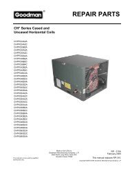
GCH95 Dimensions<br />
Model A B C D E<br />
GCH950453BXA 17½” 16” 12⅜” 14½” 16”<br />
GCH950703BXA 17½” 16” 12⅜” 14½” 16”<br />
GCH950704CXA 21” 19½” 16⅜” 18” 19½”<br />
GCH950904CXA 21” 19½” 16⅜” 18” 19½”<br />
GCH950905DXA 24½” 23” 20⅜” 21½” 23”<br />
GCH951155DXA 24½” 23” 20⅜” 21½” 23”<br />
Notes:<br />
• Installer must supply one or two PVC pipes: one for combustion air (optional) and one for the flue outlet (required). Vent pipe must<br />
be either 2” or 3” in diameter, depending upon furnace input, number of elbows, length of run, and installation (1 or 2 pipes). The<br />
optional combustion air pipe is dependent on installation/code requirements and must be 2” or 3” diameter PVC.<br />
• Line voltage wiring can enter through the right or left side of furnace. Low-voltage wiring can enter through the right or left side of furnace.<br />
• Conversion kits for high-altitude natural gas operation are available. Contact your Goodman distributor or dealer for details.<br />
• Installer must supply the following gas line fittings, according to which entrance is used:<br />
Left: One 90º street elbow; one 2½” pipe nipple; one 90º elbow; straight pipe; one ground joint union<br />
Right: Straight pipe to reach gas valve<br />
• Installations using a bottom return: Failure to unfold duct flanges will reduce airflow area by approximately<br />
18%. This could result in performance and noise issues.<br />
Minimum Clearances to Combustible Materials<br />
Position Sides Rear Front Bottom Flue Top<br />
Downflow 0” 0” 1” NC 0” 1”<br />
Horizontal 6” 0” 1” C 0” 4”<br />
C = Combustible: If placed on combustible floor, the floor MUST be wood ONLY.<br />
NC = Non-Combustible: A combustible floor sub-base must be used for installation on combustible flooring<br />
Notes:<br />
• For servicing or cleaning, a 24” front clearance is recommended.<br />
• Unit connections (electrical, flue and drain) may necessitate greater clearances than the minimum clearances listed below.<br />
• In all cases, accessibility clearance must take precedence over clearances from the enclosure where accessibility clearances are greater.<br />
6 www.amana-hac.com SS-DGMH95
<strong>Product</strong> <strong>Specifications</strong><br />
GMH95 Airflow Data<br />
(CFM & Temperature Rise vs. External Static Pressure)<br />
Model<br />
Motor<br />
Speed<br />
Tons<br />
AC¹<br />
External Static Pressure, (Inches Water Column)<br />
0.1 0.2 0.3 0.4 0.5 0.6 0.7 0.8<br />
CFM Rise CFM Rise CFM Rise CFM Rise CFM Rise CFM CFM CFM<br />
High 3 1,352 29 1,318 30 1,260 31 1,202 33 1,128 35 1,044 955 853<br />
GMH95<br />
0453BXA<br />
Med 2.5 1,214 32 1,172 34 1,123 35 1,064 37 1,012 39 938 859 741<br />
Med-Lo 2 997 40 994 40 960 41 923 43 884 45 817 741 611<br />
Low 1.5 757 52 753 52 734 54 704 56 674 59 620 524 438<br />
High 3 1,449 41 1,409 42 1,326 45 1,273 47 1,201 49 1,194 1,136 1,018<br />
GMH95<br />
0703BXA<br />
Med 2.5 1,192 50 1,172 51 1,141 52 1,094 54 1,046 57 973 904 793<br />
Med-Lo 2 981 61 962 62 943 63 917 65 888 67 830 764 665<br />
Low 1.5 750 79 730 81 714 83 692 86 657 90 620 570 502<br />
High 4 2,069 29 1,965 30 1,871 32 1,756 34 1,661 36 1,549 1,415 1,275<br />
GMH95<br />
0704CXA<br />
Med 3.5 1,752 34 1,724 34 1,667 36 1,603 37 1,488 40 1,402 1,290 1,082<br />
Med-Lo 3 1,437 41 1,437 41 1,417 42 1,369 43 1,320 45 1,256 1,140 984<br />
Low 2.5 1,184 50 1,177 50 1,161 51 1,132 52 1,095 54 1,047 928 837<br />
High 4 1,970 40 1,874 42 1,757 45 1,667 48 1,566 51 1,431 1,334 1,182<br />
GMH95<br />
0904CXA<br />
Med 3.5 1,713 46 1,650 48 1,572 50 1,510 52 1,418 56 1,313 1,211 1,079<br />
Med-Lo 3 1,439 55 1,412 56 1,370 58 1,327 60 1,260 63 1,166 1,078 956<br />
Low 2.5 1,183 67 1,155 69 1,122 71 1,108 72 1,062 75 1,011 931 816<br />
High 5 2,147 37 2,114 37 2,057 39 2,030 39 1,978 40 1,889 1,784 1,713<br />
GMH95<br />
0905CXA<br />
Med 4 1,675 47 1,686 47 1,640 48 1,623 49 1,557 51 1,501 1,455 1,360<br />
Med-Lo 3.5 1,489 53 1,470 54 1,436 55 1,409 56 1,361 58 1,318 1,243 1,130<br />
Low 3 1,307 61 1,265 63 1,234 64 1,203 66 1,168 68 1,096 1,053 991<br />
High 5 2,134 46 2,103 47 2,029 48 1,941 51 1,906 51 1,818 1,733 1,625<br />
GMH95<br />
1155DXA<br />
Med 4 1,678 58 1,643 60 1,643 60 1,577 62 1,527 64 1,489 1,423 1,339<br />
Med-Lo 3.5 1,453 68 1,440 68 1,426 69 1,363 72 1,349 73 1,314 1,253 1,205<br />
¹ @0.5” ESP<br />
Low 3 1,259 78 1,239 79 1,220 80 1,181 83 1,159 85 1,118 1,082 1,015<br />
Notes:<br />
• CFM in chart is without filter(s). Filters do not ship with this furnace, but must be provided by the installer.<br />
• All furnaces ship as high-speed cooling and medium-speed heating. Installer must adjust blower cooling & heating speed as needed.<br />
• For most applications, about 400 CFM per ton when cooling is desirable.<br />
• INSTALLATION IS TO BE ADJUSTED TO OBTAIN TEMPERATURE RISE WITHIN THE RANGE SPECIFIED ON THE RATING PLATE.<br />
• The chart is for information only. For satisfactory operation, external static pressure should not exceed value shown on the rating plate.<br />
• The above chart is for furnaces installed at 0-2000 feet. At higher altitudes, a properly de-rated unit will have approximately<br />
the same temperature rise at a particular CFM, while ESP at the CFM will be lower.<br />
SS-DGMH95 www.amana-hac.com 7
<strong>Product</strong> <strong>Specifications</strong><br />
GCH95 Airflow Data<br />
Model<br />
GCH95<br />
0453BXA<br />
GCH95<br />
0703BXA<br />
GCH95<br />
0704CXA<br />
GCH95<br />
0904CXA<br />
GCH95<br />
0905DXA<br />
GCH95<br />
1155DXA<br />
Motor<br />
Speed<br />
Tons<br />
AC¹<br />
(CFM & Temperature Rise vs. External Static Pressure)<br />
External Static Pressure, (Inches Water Column)<br />
0.1 0.2 0.3 0.4 0.5 0.6 0.7 0.8<br />
CFM Rise CFM Rise CFM Rise CFM Rise CFM Rise CFM CFM CFM<br />
High 3 1,415 28 1,352 30 1,290 31 1,196 34 1,127 36 1,035 936 825<br />
Med 2.5 1,221 33 1,178 34 1,127 36 1,073 38 1,007 40 932 834 733<br />
Med-Lo 2 1,034 39 1,000 40 976 41 935 43 881 46 818 733 662<br />
Low 1.5 860 47 845 48 812 50 783 51 740 54 682 619 534<br />
High 3 1,431 42 1,368 44 1,296 47 1,228 49 1,150 53 1,055 962 860<br />
Med 2.5 1,212 50 1,182 51 1,138 53 1,091 55 1,019 59 944 871 769<br />
Med-Lo 2 1,002 60 978 62 956 63 921 66 878 69 825 738 647<br />
Low 1.5 813 74 805 75 790 76 759 80 726 83 689 644 605<br />
High 4 1,755 34 1,674 36 1,632 37 1,510 40 1,423 42 1,325 1,241 1,116<br />
Med 3.5 1,656 36 1,585 38 1,536 39 1,429 42 1,355 45 1,268 1,145 1,059<br />
Med-Lo 3 1,551 39 1,488 41 1,427 42 1,353 45 1,290 47 1,195 1,100 1,017<br />
Low 2.5 1,286 47 1,258 48 1,241 49 1,185 51 1,112 54 1,067 983 886<br />
High 4 1,734 46 1,652 49 1,578 51 1,508 53 1,413 57 1,336 1,248 1,154<br />
Med 3.5 1,642 49 1,558 52 1,487 54 1,418 57 1,336 60 1,243 1,164 1,039<br />
Med-Lo 3 1,522 53 1,458 55 1,396 58 1,321 61 1,253 64 1,182 1,101 986<br />
Low 2.5 1,287 63 1,244 65 1,184 68 1,148 70 1,098 73 1,034 953 849<br />
High 5 2,189 37 2,109 38 2,025 40 1,948 41 1,862 43 1,757 1,644 1,537<br />
Med 4 1,885 43 1,831 44 1,776 45 1,711 47 1,637 49 1,539 1,453 1,346<br />
Med-Lo 3.5 1,665 48 1,627 50 1,584 51 1,524 53 1,462 55 1,400 1,323 1,220<br />
Low 3 1,474 55 1,440 65 1,401 57 1,356 59 1,310 61 1,255 1,193 1,109<br />
High 5 2,134 46 2,103 47 2,029 48 1,941 51 1,906 51 1,818 1,733 1,625<br />
Med 4 1,678 58 1,643 60 1,643 60 1,577 62 1,527 64 1,489 1,423 1,339<br />
Med-Lo 3.5 1,453 68 1,440 68 1,426 69 1,363 72 1,349 73 1,314 1,253 1,205<br />
Low 3 1,259 78 1,239 79 1,220 80 1,181 83 1,159 85 1,118 1,082 1,015<br />
¹ @0.5” ESP<br />
Notes:<br />
• CFM in chart is without filter(s). Filters do not ship with this furnace, but must be provided by the installer.<br />
• All furnaces ship as high-speed cooling and medium-speed heating. Installer must adjust blower cooling & heating speed as needed.<br />
• For most applications, about 400 CFM per ton when cooling is desirable.<br />
• INSTALLATION IS TO BE ADJUSTED TO OBTAIN TEMPERATURE RISE WITHIN THE RANGE SPECIFIED ON THE RATING PLATE.<br />
• The chart is for information only. For satisfactory operation, external static pressure should not exceed value shown on the rating plate.<br />
• The above chart is for furnaces installed at 0-2000 feet. At higher altitudes, a properly de-rated unit will have approximately<br />
the same temperature rise at a particular CFM, while ESP at the CFM will be lower.<br />
8 www.amana-hac.com SS-DGMH95
<strong>Product</strong> <strong>Specifications</strong><br />
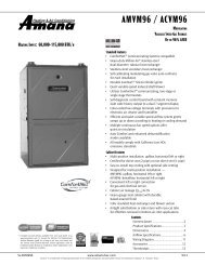
Wiring Diagram — GMH95<br />
Wiring is subject to change. Always<br />
refer to the wiring diagram or the<br />
⚠ Warning<br />
unit for the most up-to-date wiring.<br />
High Voltage: Disconnect all power before servicing or installing this unit. Multiple power<br />
sources may be present. Failure to do so may cause property damage, personal injury, or death. ⚡<br />
SS-DGMH95 www.amana-hac.com 9
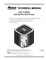
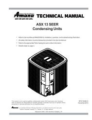
<strong>Product</strong> <strong>Specifications</strong><br />
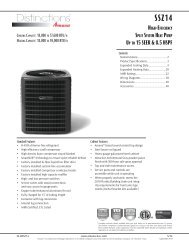
Wiring Diagram — GCH95 / GMH950905C<br />
HUMIDIFIER<br />
INTEGRATED<br />
CONTROL MODULE<br />
24V THERMOSTAT<br />
CONNECTIONS<br />
RD<br />
GND<br />
WH<br />
OR<br />
COLOR CODES:<br />
YL YELLOW<br />
OR ORANGE<br />
PU PURPLE<br />
GN GREEN<br />
BK BLACK<br />
C G R W<br />
DIAGNOSTIC<br />
LED<br />
115 VAC HOT AND PARK TERMINALS<br />
COOL-H<br />
WH<br />
GND<br />
ID BLOWER<br />
PRESSURE<br />
SWITCH<br />
2 CIRCUIT<br />
CONNECTOR<br />
HOT<br />
SURFACE<br />
IGNITER<br />
24 VAC<br />
115 VAC<br />
HEAT-H<br />
BLOWER COMPARTMENT<br />
0<br />
BR BR<br />
CAPACITOR<br />
BURNER COMPARTMENT<br />
N<br />
O<br />
24 VAC<br />
HUMIDIFIER<br />
INTEGRATED<br />
CONTROL<br />
MODULE<br />
ON<br />
FUSE<br />
OFF<br />
SEE<br />
NOTE 4<br />
PK PINK<br />
BR BROWN<br />
WH WHITE<br />
BL BLUE<br />
GY GRAY<br />
RD RED<br />
0140F01027-B<br />
BK (HI)<br />
BL (MED)<br />
OR (MED LOW)<br />
RD (LOW)<br />
AUTO RESET<br />
PR IMARY LIMIT<br />
CONTROL<br />
PM<br />
C<br />
YL<br />
LINE-H<br />
GY<br />
OR<br />
OR<br />
RD<br />
GAS VALVE<br />
BK<br />
BK<br />
( SINGLE CONTROL ON 45K BTU )<br />
C<br />
1<br />
OR<br />
PK<br />
YL<br />
BK<br />
WH WH<br />
INDUCED DRAFT<br />
BLOWER<br />
WH<br />
C<br />
Y<br />
2ND<br />
STAGE<br />
DELAY<br />
MODE<br />
HEAT<br />
OFF<br />
DELAY<br />
FACTORY SETTINGS<br />
*SHOWN<br />
SEE<br />
NOTE 6<br />
HI<br />
XFMR-H<br />
CIRCULATOR<br />
BLOWER<br />
BL<br />
N<br />
O<br />
PU<br />
MANUAL RESET ROLLOUT LIMIT CONTROL(S)<br />
24 VAC<br />
HUMIDIFIER<br />
WH<br />
GY<br />
4 0 V A<br />
T R A N S F O R M E R<br />
3<br />
2<br />
2<br />
1<br />
6 5 4<br />
9 8 7<br />
12 11 10<br />
OR<br />
GY<br />
RD<br />
GY<br />
OR<br />
115 VAC NEUTRAL<br />
TERMINALS<br />
1<br />
2<br />
3<br />
4<br />
5<br />
6<br />
7<br />
8 8 FLASHES = CHECK IGNITER OR IMPROPER GROUNDING<br />
C<br />
BK<br />
*<br />
*<br />
*<br />
STEADY ON = NORMAL OPERATION<br />
OFF = CONTROL FAILURE<br />
1 FLASH =<br />
2 FLASHES = PRESSURE SWITCH STUCK CLOSED<br />
3 FLASHES = PRESSURE SWITCH STUCK OPEN<br />
4 FLASHES = OPEN HIGH LIMIT<br />
5 FLASHES = FLAME SENSE WITHOUT GAS VALVE<br />
6 FLASHES =<br />
7 FLASHES = LOW FLAME SIGNAL<br />
OPEN ROLLOUT OR OPEN FUSE<br />
1<br />
2<br />
3<br />
SYSTEM LOCKOUT (RETRIES EXCEEDED)<br />
PK<br />
FRONT COVER<br />
PRESSURE SWITCH<br />
GY<br />
GND<br />
CONTINUOUS/RAPID FLASHES = REVERSED 115 VAC POLARITY<br />
FS<br />
BR<br />
PU<br />
OR<br />
BL<br />
GR<br />
YL<br />
WH<br />
PU<br />
OR<br />
OR<br />
BR<br />
WH<br />
GY<br />
GY<br />
WH<br />
WH<br />
RD<br />
PU<br />
(HONEYWELL)<br />
BL<br />
GR<br />
GY<br />
OR<br />
YL<br />
OR<br />
GY<br />
RD<br />
BLOWER<br />
COMPARTMENT<br />
DOOR SWITCH<br />
(OPEN WHEN<br />
DOOR OPEN)<br />
GR<br />
BR<br />
OR<br />
BK<br />
BL<br />
BK<br />
24V THERMOSTAT CONNECTIONS<br />
INTEGRATED CONTROL MODULE<br />
FLAME<br />
SENSOR<br />
LOW VOLTAGE (24V)<br />
LOW VOLTAGE FIELD<br />
HI VOLTAGE (115V)<br />
HI VOLTAGE FIELD<br />
JUNCTION<br />
INTERNAL TO<br />
INTEGRATED CONTROL<br />
EQUIPMENT GND<br />
FIELD GND<br />
IGNITER<br />
OVERCURRENT<br />
PROT. DEVICE<br />
NOTES:<br />
1. SET HEAT ANTICIPATOR ON ROOM THERMOSTAT AT 0.7 AMPS.<br />
2. MANUFACTURER'S SPECIFIED REPLACEMENT PARTS MUST BE USED WHEN SERVICING.<br />
3. IF ANY OF THE ORIGINAL WIRE AS SUPPLIED WITH THE FURNACE MUST BE REPLACED, IT MUST BE REPLACED WITH WIRING MATERIAL HAVING A TEMPERATURE<br />
RATING OF AT LEAST 105°C. USE COPPER CONDUCTORS ONLY.<br />
4. IF HEATING AND COOLING BLOWER SPEEDS ARE NOT THE SAME, DISCARD JUMPER BEFORE CONNECTING BLOWER LEADS. UNUSED BLOWER LEADS MUST BE<br />
PLACED ON "PARK" TERMINALS OF INTEGRATED CONTROL OR TAPED.<br />
5. UNIT MUST BE PERMANENTLY GROUNDED AND CONFORM TO N.E.C. AND LOCAL CODES.<br />
6. TO RECALL THE LAST 5 FAULTS, MOST RECENT TO LEAST RECENT, DEPRESS SWITCH FOR MORE THAN 2 SECONDS WHILE IN STANDBY (NO THERMOSTAT INPUTS)<br />
C<br />
G<br />
Y<br />
W<br />
R<br />
TH (3)<br />
XFMR-H<br />
LINE-H<br />
DOOR<br />
SWITCH<br />
WARNING:<br />
DISCONNECT POWER<br />
BEFORE SERVICING.<br />
WIRING TO UNIT<br />
MUST BE<br />
PROPERLY<br />
POLARIZED<br />
AND GROUNDED.<br />
JUNCTION<br />
BOX<br />
WH<br />
BK<br />
TO<br />
MICRO<br />
JUNCTION BOX<br />
L GND N<br />
DISCONNECT<br />
TO 115VAC/ 1 Ø /60 HZ POWER SUPPLY WITH<br />
OVERCURRENT PROTECTION DEVICE<br />
TERMINAL<br />
PLUG CONNECTION<br />
FS<br />
IGN<br />
IND<br />
EAC-H<br />
TR (6)<br />
GND (8)<br />
MVC (9)<br />
MVH (12)<br />
MVL(2)<br />
PS (10)<br />
PSO (4)<br />
HLI (7)<br />
HLO (1)<br />
RO1 (5)<br />
AUTO RESET PRIMARY<br />
LIMIT CONTROL<br />
RO2 (11)<br />
HOT SURFACE<br />
IGNITER<br />
LO<br />
HEAT-H<br />
COOL-H<br />
HI<br />
HEAT-H<br />
FLAME SENSOR<br />
ID<br />
BLWR<br />
24 VAC<br />
115 VAC<br />
CIRCULATOR<br />
BLWR<br />
ELECTRONIC<br />
AIR CLEANER<br />
WARNING:DISCONNECT POWER BEFORE<br />
SERVICING.WIRING TO UNIT MUST BE<br />
PROPERLY POLARIZED AND GROUNDED.<br />
DISCONNECT<br />
GND<br />
AUXILIARY LIMIT CONTROLS<br />
MANUAL RESET ROLLOUT<br />
LIMIT CONTROL(S)<br />
(SINGLE CONTROL ON 45K BTU)<br />
C<br />
NO<br />
FRONT COVER<br />
PRESSURE SWITCH<br />
C<br />
40 VA<br />
TRANSFORMER<br />
N<br />
GND<br />
L<br />
FIELD SPLICE<br />
SWITCH (TEMP.)<br />
SWITCH (PRESS.)<br />
C<br />
GAS<br />
HI VALVE<br />
PM<br />
LINE NEUTRALS<br />
NO<br />
ID BLOWER<br />
PRESSURE<br />
SWITCH<br />
POWER SUPPLY WITH<br />
OVERCURRENT PROTECTION<br />
DEVICE<br />
INTEGRATED CONTROL MODULE<br />
TO 115 VAC / 1Ø / 60HZ<br />
High Voltage: Disconnect all power before servicing or installing this unit. Multiple power<br />
sources may be present. Failure to do so may cause property damage, personal injury, or death. ⚡<br />
Wiring is subject to change. Always<br />
refer to the wiring diagram or the<br />
⚠ Warning<br />
unit for the most up-to-date wiring.<br />
10 www.amana-hac.com SS-DGMH95
<strong>Product</strong> <strong>Specifications</strong><br />
Accessories — GMH95<br />
Accessory<br />
Description<br />
GMH95<br />
0453BXA<br />
GMH95<br />
0703BXA<br />
GMH95<br />
0704CXA<br />
GMH95<br />
0904CXA<br />
GMH95<br />
0905CXA<br />
GMH95<br />
1155DXA<br />
LPM-06 LP Conversion Kit (Springs & Orifice)* √ √ √ √ √ √<br />
LPLP03 LP Gas Low-Pressure Kit √ √ √ √ √ √<br />
GSAS Electronic Air Cleaners (-10, -11, -12, -18) √ √ √ √ √ √<br />
GMU Media Air Cleaners (1620, 2020, 1625, 2025) √ √ √ √ √ √<br />
HANG11 High Altitude Natural Gas Kit 1 1 1 1 1 1<br />
HANG12 High Altitude Natural Gas Kit 2 2 2 2 2 2<br />
HALP10 High Altitude LP Gas Kit 3 3 3 3 3 3<br />
HAPS27 High Altitude Pressure Switch Kit 3 3 3 3 3 3<br />
FTK04 Twinning Kit √ √ √ √ √ √<br />
EFR01 External Filter Rack √ √ √ √ √ √<br />
DCVK-20 Horizontal/Vertical Concentric Vent Kit (2”) √ √ --- --- --- ---<br />
DCVK-30 Horizontal/Vertical Concentric Vent Kit (3”) √ √ √ √ √ √<br />
0170K00000S Flush-mount Vent Kit √ √ √ √ √ √<br />
* White-Rodgers and Honeywell valves<br />
√ Indicates accessories available for this model<br />
1 Indicates 7,001’ to 9,000’ altitude<br />
2 Indicates 9,001’ to 11,000’ altitude<br />
3 Indicates 7,001’ to 11,000’ altitude<br />
Notes<br />
• All installations above 7,000’ require a pressure switch change. For installation in Canada, furnaces are certified only to 4,500’.<br />
• Downflow Floor base: When the GCH9 model is installed directly on a wood floor, a downflow floor<br />
base must be used. Those model numbers are: CFB17, CFB21 and CFB24.<br />
SS-DGMH95 www.amana-hac.com 11
<strong>Product</strong> <strong>Specifications</strong><br />
Accessories — GCH95<br />
Accessory<br />
Description<br />
GCH95<br />
0453BXA<br />
GCH95<br />
0703BXA<br />
GCH95<br />
0704CXA<br />
GCH95<br />
0904CXA<br />
GCH95<br />
0905CXA<br />
GCH9<br />
1155DXA<br />
LPM-06 LP Conversion Kit (Springs & Orifice)* √ √ √ √ √ √<br />
LPLP03 LP Gas Low-Pressure Kit √<br />
GSAS Electronic Air Cleaners (-10, -11, -12, -18) √ √ √ √ √ √<br />
GMU Media Air Cleaners (1620, 2020, 1625, 2025) √ √ √ √ √ √<br />
HANG11 High Altitude Natural Gas Kit 1 1 1 1 1 1<br />
HANG12 High Altitude Natural Gas Kit 2 2 2 2 2 2<br />
HALP10 High Altitude LP Gas Kit 3 3 3 3 3 3<br />
HAPS27 High Altitude Pressure Switch Kit 3 3 3 3 3 3<br />
EFR01 External Filter Rack √ √ √ √ √ √<br />
DCVK-20 Horizontal/Vertical Concentric Vent Kit (2”) √ √ --- --- --- ---<br />
DCVK-30 Horizontal/Vertical Concentric Vent Kit (3”) √ √ √ √ √ √<br />
0170K00000S Flush-mount Vent Kit √ √ √ √ √ √<br />
* White-Rodgers and Honeywell valves<br />
√ Indicates accessories available for this model<br />
1 Indicates 7,001’ to 9,000’ altitude<br />
2 Indicates 9,001’ to 11,000’ altitude<br />
3 Indicates 7,001’ to 11,000’ altitude<br />
Notes<br />
• All installations above 7,000’ require a pressure switch change. For installation in Canada, furnaces are certified only to 4,500’.<br />
• Downflow Floor base: When the GCH9 model is installed directly on a wood floor, a downflow floor<br />
base must be used. Those model numbers are: CFB17, CFB21 and CFB24.<br />
<strong>Amana</strong>® is a trademark of Maytag Corporation or its related companies and used under license to Goodman Company, L.P. All rights reserved. Our continuing<br />
commitment to quality products may mean a change in specifications without notice. © 2014 • Goodman Company, L.P. • Houston, Texas • Printed in the USA.<br />
12 www.amana-hac.com SS-DGMH95