MALMS⢠Transverse - Airports International
MALMS⢠Transverse - Airports International
MALMS⢠Transverse - Airports International

Create successful ePaper yourself
Turn your PDF publications into a flip-book with our unique Google optimized e-Paper software.
• Course Detail Chart: defines the performance of each<br />
individual light on the latest (or other user defined)<br />
survey date. As well as a visual indication of overall<br />
performance, this identifies where unserviceable lights<br />
are located.<br />
• Isocandela Diagrams: Show beam orientation and beam<br />
intensity, either for all lights or those listed on the repair<br />
report. This information can be used to differentiate<br />
between different types of faults (such as low light<br />
output and poor alignment) and help define<br />
maintenance requirements. Isocandela Diagrams for<br />
both sides on two dates can be displayed alongside each<br />
other to show the difference between the two. This<br />
provides a visual indication of changes in light<br />
performance and effectiveness of planned work activity.<br />
• Location History Chart: Bar chart showing average<br />
intensity for one or both sides of user specified light over<br />
time. This provides visual indication of trends in<br />
individual light performance.<br />
• Repair Report: List of lights that, on the last survey run,<br />
were below a user defined standard. Normally the<br />
standard would be set in line with the failure level<br />
defined by the Regulatory Authority (i.e. 50% of ICAO<br />
Standard, 70% of FAA standard) and thus lights listed on<br />
the Repair Report would be classed as priority repairs.<br />
• Maintenance Report: List of lights that, on the last survey<br />
run, were below a user defined standard. Normally the<br />
standard would be set to ensure that required<br />
maintenance, i.e. cleaning, re-lamping, etc. is undertaken<br />
before performance falls below the failure level defined<br />
by the Regulatory Authority.<br />
• Alignment Report: List of lights that have been<br />
consistently out of alignment since a user defined date.<br />
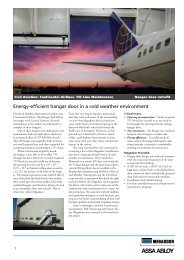
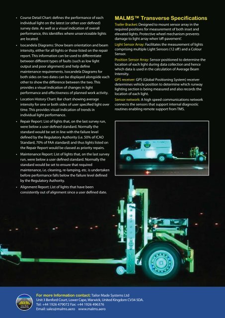
MALMS <strong>Transverse</strong> Specifications<br />
Trailer Bracket: Designed to mount sensor array in the<br />
required positions for measurement of both inset and<br />
elevated lights. Protective wheel mechanism prevents<br />
damage to light array when ‘off-pavement’.<br />
Light Sensor Array: Facilitates the measurement of lights<br />
comprising multiple Light Sensors (12 off) and a Colour<br />
Sensor.<br />
Position Sensor Array: Sensor positioned to determine the<br />
location of each light during data collection and hence<br />
which data is used in the calculation of Average Beam<br />
Intensity.<br />
GPS receiver: GPS (Global Positioning System) receiver<br />
determines vehicle position to determine which runway<br />
lighting section is being measured and also records the<br />
location of each light.<br />
Sensor network: A high speed communications network<br />
connects the sensors that support internal diagnostic<br />
routines enabling remote support from TMS.<br />
Tailor Made<br />
Systems Ltd<br />
For more Information contact: Tailor Made Systems Ltd<br />
Unit 3 Benford Court, Lower Cape, Warwick, United Kingdom CV34 5DA.<br />
Tel: +44 1926 479072 Fax: +44 1926 496376<br />
Email: sales@malms.aero www.malms.aero