MALMS⢠Transverse - Airports International
MALMS⢠Transverse - Airports International
MALMS⢠Transverse - Airports International

Create successful ePaper yourself
Turn your PDF publications into a flip-book with our unique Google optimized e-Paper software.
Tailor Made<br />
Systems Ltd<br />
MALMS TM <strong>Transverse</strong><br />
Airfield Lighting Photometric Test System<br />
Advantages<br />
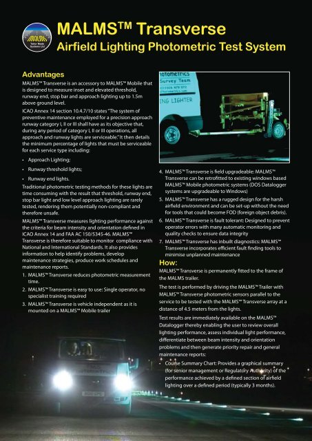
MALMS <strong>Transverse</strong> is an accessory to MALMS Mobile that<br />
is designed to measure inset and elevated threshold,<br />
runway end, stop bar and approach lighting up to 1.5m<br />
above ground level.<br />
ICAO Annex 14 section 10.4.7/10 states “The system of<br />
preventive maintenance employed for a precision approach<br />
runway category I, II or III shall have as its objective that,<br />
during any period of category I, II or III operations, all<br />
approach and runway lights are serviceable.” It then details<br />
the minimum percentage of lights that must be serviceable<br />
for each service type including:<br />
• Approach Lighting;<br />
• Runway threshold lights;<br />
• Runway end lights.<br />
Traditional photometric testing methods for these lights are<br />
time consuming with the result that threshold, runway end,<br />
stop bar light and low level approach lighting are rarely<br />
tested, rendering them potentially non-compliant and<br />
therefore unsafe.<br />
MALMS <strong>Transverse</strong> measures lighting performance against<br />
the criteria for beam intensity and orientation defined in<br />
ICAO Annex 14 and FAA AC 150/5345-46. MALMS<br />
<strong>Transverse</strong> is therefore suitable to monitor compliance with<br />
National and <strong>International</strong> Standards. It also provides<br />
information to help identify problems, develop<br />
maintenance strategies, produce work schedules and<br />
maintenance reports.<br />
1. MALMS <strong>Transverse</strong> reduces photometric measurement<br />
time.<br />
2. MALMS <strong>Transverse</strong> is easy to use: Single operator, no<br />
specialist training required<br />
3. MALMS <strong>Transverse</strong> is vehicle independent as it is<br />
mounted on a MALMS Mobile trailer<br />
4. MALMS <strong>Transverse</strong> is field upgradeable: MALMS<br />
<strong>Transverse</strong> can be retrofitted to existing windows based<br />
MALMS Mobile photometric systems (DOS Datalogger<br />
systems are upgradeable to Windows)<br />
5. MALMS <strong>Transverse</strong> has a rugged design for the harsh<br />
airfield environment and can be set-up without the need<br />
for tools that could become FOD (foreign object debris).<br />
6. MALMS <strong>Transverse</strong> is fault tolerant: Designed to prevent<br />
operator errors with many automatic monitoring and<br />
quality checks to ensure data integrity<br />
7. MALMS <strong>Transverse</strong> has inbuilt diagnostics: MALMS<br />
<strong>Transverse</strong> incorporates efficient fault finding tools to<br />
minimise unplanned maintenance<br />
How:<br />
MALMS <strong>Transverse</strong> is permanently fitted to the frame of<br />
the MALMS trailer.<br />
The test is performed by driving the MALMS Trailer with<br />
MALMS <strong>Transverse</strong> photometric sensors parallel to the<br />
service to be tested with the MALMS <strong>Transverse</strong> array at a<br />
distance of 4.5 meters from the lights.<br />
Test results are immediately available on the MALMS<br />
Datalogger thereby enabling the user to review overall<br />
lighting performance, assess individual light performance,<br />
differentiate between beam intensity and orientation<br />
problems and then generate priority repair and general<br />
maintenance reports:<br />
• Course Summary Chart: Provides a graphical summary<br />
(for senior management or Regulatory Authority) of the<br />
performance achieved by a defined section of airfield<br />
lighting over a defined period (typically 3 months).
• Course Detail Chart: defines the performance of each<br />
individual light on the latest (or other user defined)<br />
survey date. As well as a visual indication of overall<br />
performance, this identifies where unserviceable lights<br />
are located.<br />
• Isocandela Diagrams: Show beam orientation and beam<br />
intensity, either for all lights or those listed on the repair<br />
report. This information can be used to differentiate<br />
between different types of faults (such as low light<br />
output and poor alignment) and help define<br />
maintenance requirements. Isocandela Diagrams for<br />
both sides on two dates can be displayed alongside each<br />
other to show the difference between the two. This<br />
provides a visual indication of changes in light<br />
performance and effectiveness of planned work activity.<br />
• Location History Chart: Bar chart showing average<br />
intensity for one or both sides of user specified light over<br />
time. This provides visual indication of trends in<br />
individual light performance.<br />
• Repair Report: List of lights that, on the last survey run,<br />
were below a user defined standard. Normally the<br />
standard would be set in line with the failure level<br />
defined by the Regulatory Authority (i.e. 50% of ICAO<br />
Standard, 70% of FAA standard) and thus lights listed on<br />
the Repair Report would be classed as priority repairs.<br />
• Maintenance Report: List of lights that, on the last survey<br />
run, were below a user defined standard. Normally the<br />
standard would be set to ensure that required<br />
maintenance, i.e. cleaning, re-lamping, etc. is undertaken<br />
before performance falls below the failure level defined<br />
by the Regulatory Authority.<br />
• Alignment Report: List of lights that have been<br />
consistently out of alignment since a user defined date.<br />
MALMS <strong>Transverse</strong> Specifications<br />
Trailer Bracket: Designed to mount sensor array in the<br />
required positions for measurement of both inset and<br />
elevated lights. Protective wheel mechanism prevents<br />
damage to light array when ‘off-pavement’.<br />
Light Sensor Array: Facilitates the measurement of lights<br />
comprising multiple Light Sensors (12 off) and a Colour<br />
Sensor.<br />
Position Sensor Array: Sensor positioned to determine the<br />
location of each light during data collection and hence<br />
which data is used in the calculation of Average Beam<br />
Intensity.<br />
GPS receiver: GPS (Global Positioning System) receiver<br />
determines vehicle position to determine which runway<br />
lighting section is being measured and also records the<br />
location of each light.<br />
Sensor network: A high speed communications network<br />
connects the sensors that support internal diagnostic<br />
routines enabling remote support from TMS.<br />
Tailor Made<br />
Systems Ltd<br />
For more Information contact: Tailor Made Systems Ltd<br />
Unit 3 Benford Court, Lower Cape, Warwick, United Kingdom CV34 5DA.<br />
Tel: +44 1926 479072 Fax: +44 1926 496376<br />
Email: sales@malms.aero www.malms.aero