Beam control of Microwave Power Beam for a Solar Power Station ...
Beam control of Microwave Power Beam for a Solar Power Station ...
Beam control of Microwave Power Beam for a Solar Power Station ...

You also want an ePaper? Increase the reach of your titles
YUMPU automatically turns print PDFs into web optimized ePapers that Google loves.
The 2 nd Joint International Conference on “Sustainable Energy and Environment (SEE 2006)”<br />
A-023 (O) 21-23 November 2006, Bangkok, Thailand<br />
<strong>Beam</strong> <strong>control</strong> <strong>of</strong> <strong>Microwave</strong> <strong>Power</strong> <strong>Beam</strong> <strong>for</strong> a <strong>Solar</strong> <strong>Power</strong> <strong>Station</strong>/Satellite<br />
Kozo Hashimoto 1,∗ , Naoki Shinohara 1 and Hiroshi Matsumoto 2<br />
1 Research Institute <strong>for</strong> Sustainable Humanosphere, Kyoto University, Gokasho, Uji, Kyoto 611-0011, Japan<br />
2 Kyoto University, Kyoto, Japan<br />
Abstract: <strong>Solar</strong> power satellite (SPS) is paid attention to as a clean, inexhaustible large-scale base-load power supply, where carbon<br />
dioxide is not exhausted. In order to send power a receiving site correctly, the ground receiving site sends a pilot signal and the SPS<br />
sends power by a microwave to the arrival direction <strong>of</strong> the signal. Two technologies related to beam <strong>control</strong> are reviewed. A system<br />
which uses a spread spectrum pilot signal is introduced. An arrival direction is estimated from the pilot signal after despreading the<br />
SS modulation. This does not respond to fake or wrong signals and is more reliable under power transmission. A single frequency can<br />
be used <strong>for</strong> both monochromatic power transmission and a carrier <strong>of</strong> the pilot signal and the antennas are shared <strong>for</strong> both power<br />
transmission and pilot signal reception. Antenna radiation patterns are optimized <strong>for</strong> high transmission efficiency and low sidelobes<br />
under a uni<strong>for</strong>mly excited array through a genetic algorithm. Radiation patterns directed to multiple directions can also be created.<br />
Keywords: <strong>Solar</strong> <strong>Power</strong> Satellite, <strong>Microwave</strong> <strong>Power</strong> Transmission, Spread Spectrum, <strong>Beam</strong> Forming, Retrodirective System<br />
1. INTRODUCTION<br />
<strong>Solar</strong> power satellite (SPS) is paid attention to as a clean, inexhaustible large-scale base-load power supply where carbon dioxide<br />
is not exhausted. The expectation is great as renewable energy since the SPS is not affected by weather and can supply electric<br />
power as a base load <strong>for</strong> 24 hours a day. The SPS is a gigantic satellite designed as an electric power station orbiting in the<br />
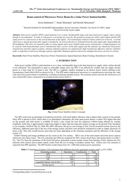
Geostationary Earth Orbit (GEO) as shown in Fig. 1. The SPS sends a high power microwave to a ground power receiving site, wher<br />
e the microwave power beam is rectified by a rectenna (rectifying antenna) system. The rectenna system converts the microwave to d<br />
irect current (DC) and is connected to an existing electric power grid [1].<br />
Fig. 1 <strong>Solar</strong> <strong>Power</strong> Satellite (Artist’s Concept)<br />
The SPS system has an advantage <strong>of</strong> producing electricity with much higher efficiency than a photovoltaic system on the ground.<br />
Since SPS is placed in GEO, where there is no atmospheric absorption, the solar input power density is about 30% higher than that<br />
on the ground, and solar power is available 24 hours a day except <strong>for</strong> near the equinoxes without being affected by weather<br />
conditions. <strong>Solar</strong> flux is approximately eight times higher in space than the long-term surface average on the ground if the insolation<br />
is, <strong>for</strong> example, 4 kWh/m 2 /day [2]. With 50% MPT efficiency, this gives a net average <strong>of</strong> four. For the terrestrial system, however, the<br />
efficiency, additional space due to the loss <strong>of</strong> the storage system, and their costs should be considered in order to supply electricity 24<br />
hours a day. This ratio would become more than ten times depending on the minimum insolation and the efficiency <strong>of</strong> the storage<br />
system [1].<br />
Global warming and energy problems are key issues in the 21st century. SPS is one <strong>of</strong> the most import and clean power sources<br />
which can solve these issues. The CO 2 emissions per kWh are compared <strong>for</strong> SPS, various fossil fuels, and nuclear power in Table 1<br />
[3]. The CO 2 from the operations <strong>of</strong> the fossil fuel power generation systems mainly comes from burning <strong>of</strong> fuel, whereas the CO 2<br />
emission from nuclear power plants mainly comes from the use <strong>of</strong> energy to produce nuclear fuel. Almost zero CO 2 emission is<br />
expected from SPS operation. The SPS System would release less CO 2 / kWh than nuclear power generation.<br />
Table 1 Comparison <strong>of</strong> relative CO2 emissions from different electricity generation systems (units: g CO 2 /kWh)<br />
Generating system Operations Construction Total<br />
SPS 0 20 20<br />
Coal 1222 3 1225<br />
Oil 844 2 846<br />
Liquefied Natural Gas (LNG) 629 2 631<br />
Nuclear power 19 3 22<br />
Corresponding auhror: kozo@rish.kyoto-u.ac.jp<br />
1
The 2 nd Joint International Conference on “Sustainable Energy and Environment (SEE 2006)”<br />
A-023 (O) 21-23 November 2006, Bangkok, Thailand<br />
A huge, clean power source is to be developed <strong>for</strong> sustainable economic activities with a sufficient suppression <strong>of</strong> CO 2 emission.<br />
Only solar technologies can provide such a huge, clean power source in the near future. The terrestrial photovoltaics, wind,<br />
geothermal, and other natural resources depend on the environmental conditions and are neither stable nor sufficient.<br />
This system transmits electric power generated by solar cells in space through microwave. The microwave power is sent to a<br />
power-receiving site on the ground or in space. The retrodircetive array is generally used <strong>for</strong> transmitting the power correctly to the<br />
receiving site. Two technologies related to beam <strong>control</strong> are reviewed in the present paper.<br />
A microwave power transmission system is introduced, which can send the power to multiple directions [4]. <strong>Power</strong> receiving sites<br />
send pilot signals and high power microwave beams are sent to respective arrival directions <strong>of</strong> the signals. The spread spectrum (SS)<br />
modulation is used <strong>for</strong> the pilot signals to differentiate them. This system is a kind <strong>of</strong> s<strong>of</strong>tware retrodirective array. Pilot signals are<br />
sent from power receiving sites. Based on the in<strong>for</strong>mation <strong>of</strong> the arrived signals, the array patterns can be synthesized <strong>for</strong> a single or<br />
multiple beams, sidelobe suppression, etc. The power is sent to the directions <strong>of</strong> the pilot signals. The conventional hardware<br />
retrodirective system is fast but complex, and the adjustment <strong>of</strong> the system is difficult. Although this system is not so fast as the<br />
hardware system, this has flexibility. Because the direct sequence spread spectrum is used <strong>for</strong> the signals, this does not respond to<br />
fake or wrong signals and is expected to be more reliable under noises and the power transmission. This is a useful technique even<br />
<strong>for</strong> a single receiving site.<br />
Antenna radiation patterns are optimized <strong>for</strong> high transmission efficiency and low sidelobes under a uni<strong>for</strong>mly excited array<br />
through a pareto evolutionally algorithm, a kind <strong>of</strong> genetic algorithm [5]. This is expected to contribute cost reduction as well. This<br />
method can also send the beams to multiple directions or multiple receiving sites.<br />
2. RETRODIRECTIVE SYSTEM<br />
In proposed SPS plans, the electric power <strong>of</strong> 1GW is supplied from a geosynchronous orbit at an altitude <strong>of</strong> 36,000 km to a power<br />
reception target with a diameter <strong>of</strong> a few km by 5.8GHz microwave. The electric power density is highest at the center <strong>of</strong> the target.<br />
The reception area is decided in consideration <strong>of</strong> the peak density and the safety to the living body. Because the product <strong>of</strong> the<br />
sending and receiving areas is constant to obtain a given transmission efficiency, the area <strong>of</strong> the power transmission side is naturally<br />
decided. It is necessary to direct the beam to the target in extremely high accuracy in order to avoid interference to existing<br />
communication networks and to transmit electricity accurately, efficiently, and safely.<br />
The high accuracy more than that generally used in communications is requested, <strong>for</strong> example, assuming accuracy 200m or less on<br />
the ground to concentrate the microwave electric power <strong>of</strong> 90% or more on the receipt site <strong>of</strong> 0.0003° or less in beam angle. Since<br />
mechanically obtaining this accuracy is impossible, a pilot signal is sent from the target on the ground, and the retrodirective system<br />
which transmits a microwave power beam to the direction <strong>of</strong> arrival is used.<br />
Based on the recent JAXA (Japan Aerospace Exploration Agency) model [6], a size <strong>of</strong> a transmitting antenna is 2kmφ at 5.8 GHz<br />
and 1.3 GW output in a geostationary orbit (GEO). The diameter <strong>of</strong> a rectenna on the ground becomes 2.5 km. The angle to the edge<br />
<strong>of</strong> the rectenna site from the SPS is 0.002º. One tenth <strong>of</strong> the value would be necessary at least. The phase difference, φ, between the<br />
antenna elements with a spacing <strong>of</strong>d when the direction <strong>of</strong> arrival (DOA) is θ measured from the broad side, is<br />
2π<br />
d<br />
φ = sinθ<br />
. (1)<br />
λ<br />
2<br />
For an array <strong>of</strong> M elements with uni<strong>for</strong>m amplitude, if the phase errors <strong>of</strong> the antenna elements are random, and their variance is Φ ,<br />
the variance <strong>of</strong> beam pointing deviation is given by [7]<br />
2 2 3<br />
= 12Φ<br />
/ M<br />
δθ . (2)<br />
This value is very small since M is more than 10 4 in one dimension. Systematic errors like errors in direction <strong>of</strong> arrival could cause<br />
pointing errors. Doppler effects are negligible in GEO [8].<br />
Fig. 2 Retrodirective system<br />
A retrodirective system (Fig. 2) send a microwave power beam correctly to the direction <strong>of</strong> arrival <strong>of</strong> a pilot signal which is sent<br />
2
The 2 nd Joint International Conference on “Sustainable Energy and Environment (SEE 2006)”<br />
A-023 (O) 21-23 November 2006, Bangkok, Thailand<br />
from a power receiving site. This is generally realized by hardware in its applications to communications [6]. The power distribution<br />
in the SPS transmitter array is Gaussian-tapered. This focuses the power in the main beam to increase the transmission efficiency and<br />
decrease the sidelobe levels. It is expensive to make the same number <strong>of</strong> retrodirective systems as transmitting antenna elements.<br />
The required response time in SPS is not so fast as communications. A s<strong>of</strong>tware retrodirective system would be useful because <strong>of</strong> the<br />
above reasons. This system measures the direction <strong>of</strong> arrival <strong>of</strong> a pilot signal and sends the beam back to its direction. Flexible beam<br />
<strong>for</strong>ming becomes possible. Even power beams can be sent to multiple directions.<br />
Intensity (m W /cm 2)<br />
10 1<br />
10 0<br />
10 -1<br />
10 -2<br />
10 -3<br />
-5 -4 -3 -2 -1 0 1 2 3 4 5<br />
10 2 Rectenna Range (km )<br />
Intensity (m W /cm 2)<br />
10 1<br />
10 0<br />
10 -1<br />
10 -2<br />
10 -3<br />
-5 -4 -3 -2 -1 0 1 2 3 4 5<br />
10 2 Rectenna Range (km )<br />
Fig. 3 Received intensity (power density) pr<strong>of</strong>iles at a rectenna site<br />
a (Left) Array with 10-dB Gaussian power distribution, b (Right) Array with uni<strong>for</strong>m excitation<br />
For reduced sidelobes and efficient energy transmission, 10-dB Gaussian tapering is generally proposed <strong>for</strong> its output power<br />
distribution <strong>of</strong> the transmitting array antenna <strong>for</strong> SPS [1]. The beam intensity pattern at the rectenna site has a non-uni<strong>for</strong>m<br />
distribution with a higher intensity in the center <strong>of</strong> the rectenna and a lower intensity at its periphery as shown in Fig. 3a. The peak<br />
microwave power density at the rectenna site is 27 mW/cm 2 <strong>for</strong> 1GW output. A typical rectenna site is 4 km in diameter <strong>for</strong> a<br />
transmitting antenna diameter <strong>of</strong> 1km operating at 5.8 GHz. Under these conditions, 93% <strong>of</strong> the transmitted power is collected. The<br />
safety requirement <strong>for</strong> the microwave power density <strong>for</strong> humans is set to 1mW/cm 2 in most countries, which is satisfied at the<br />
periphery (±2km). In the uni<strong>for</strong>m excitation as shown in Fig. 3b, the main beam is narrower, side lobe levels are higher, and the<br />
collected energy is lower.<br />
3. SPREAD SPECTRUM PILOT SIGNAL AND ITS APPLICATION<br />
A beam <strong>control</strong> system <strong>for</strong> microwave power transmission with Spread Spectrum (SS) pilot signals is developed <strong>for</strong> SPS. The SS<br />
modulation is used to differentiate pilot signals sent from power receiving sites. An arrival direction is estimated from the phase<br />
difference between two channels after despreading the SS modulation. This system is a kind <strong>of</strong> s<strong>of</strong>tware retrodirective array. This<br />
does not respond to fake or wrong signals and is more reliable under power transmission. The proposed system is useful even <strong>for</strong> a<br />
single receiving site [4].<br />
A new system is introduced in the SS system where a single frequency can be used <strong>for</strong> both monochromatic power transmission<br />
and a carrier <strong>of</strong> the pilot signal and the antennas are shared <strong>for</strong> both power transmission and pilot signal reception [4]. Band<br />
elimination filters (BEFs) and s<strong>of</strong>tware synchronization detection are used in this system. Fundamental characteristics <strong>of</strong> the phasedifference<br />
detection are evaluated. The phase detecting circuit works well and the direction <strong>of</strong> arrival has been successfully detected<br />
under transmitting power from the same antennas. We can use this system to transmit energy in SPS, when we have BEFs that have<br />
larger elimination and amplifiers that have a larger dynamic range and lower noise.<br />
System Configuration<br />
Pilot signal transmitter<br />
<strong>Power</strong> Transmitting Signal<br />
(2.45GHz)<br />
2.45GHz Antenna<br />
Spectrum Spread Pilot Signal<br />
(⇒2.45GHz)<br />
Phase Shifter<br />
Down Converter<br />
Phase Shifter<br />
Down Converter<br />
Phase Shifter<br />
Down Converter<br />
Phase Controlled<br />
Magnetron<br />
or<br />
FET AMP<br />
Despread circuit<br />
(including MIXER) Spread code<br />
A/D Converter<br />
Control signal<br />
Computer<br />
MIXER<br />
A/D Converter<br />
MIXER<br />
A/D Converter<br />
Fig. 4 Block diagram <strong>of</strong> spread spectrum pilot system [4]<br />
3
The 2 nd Joint International Conference on “Sustainable Energy and Environment (SEE 2006)”<br />
A-023 (O) 21-23 November 2006, Bangkok, Thailand<br />
The SPS needs to send a microwave power beam to a receiving site correctly. A pilot signal is sent from the receiving site to the<br />
SPS and then the power is beamed back to its original arrival direction. This function is the same as a retrodirective antenna system.<br />
This type <strong>of</strong> beam <strong>control</strong> is one <strong>of</strong> the most important techniques <strong>for</strong> microwave power transmission system used on SSPS. The<br />
objective is to develop a new microwave power transmission system using a SS pilot signal with a single frequency <strong>for</strong> the power<br />
transmission and the pilot signal, and to evaluate this system through experiments. The M-series PN code with the length <strong>of</strong> 1023 is<br />
used <strong>for</strong> the SS modulation. This system is based on s<strong>of</strong>tware retrodirective response. The antennas <strong>for</strong> power transmission and pilot<br />
signal share a common frequency band.<br />
Fig. 4 shows a retrodirective transmitting system. Three channels <strong>of</strong> the system are shown. This system receives a spread spectrum<br />
pilot signal, detects the direction <strong>of</strong> arrival, and transmits a power beam in the desired direction by s<strong>of</strong>tware <strong>control</strong>. Both the power<br />
transmitting and receiving frequencies are equal to 2.45GHz. This frequency is selected since most SPS models use the ISM<br />
frequency band <strong>for</strong> energy transmission. Transmitting power is basically generated by a phase <strong>control</strong>led magnetron or sent from<br />
FET amplifiers. This is sent to each antenna through a phase shifter <strong>for</strong> beam steering and a circulator. A signal generator is used as<br />
the transmitter since quite low phase noise is required <strong>for</strong> better phase difference measurements. The transmission direction is fixed<br />
to the broadside in the present experiment. The received signal goes through the circulator, is down-converted to 10.7MHz,<br />
despread, down-converted to 10 kHz, and A/D converted to measure the phase difference by Fourier analysis. Because the direct<br />
sequence spread spectrum is used <strong>for</strong> the pilot signal, it does not respond to erroneous signals and is more reliable under noise. The<br />
despread circuit supplies the PN code <strong>for</strong> despreading to other mixers which share the code. This works under multiple pilot signals<br />
and is a useful technique even <strong>for</strong> a single receiving site.<br />
Effect <strong>of</strong> BEF and S<strong>of</strong>t Sync.<br />
Fig. 5 Effect <strong>of</strong> band elimination filter and s<strong>of</strong>tware synchronization [7]<br />
Fig. 5 shows the effect <strong>of</strong> band elimination filter (BEF) and s<strong>of</strong>tware SS synchronization. The two lines starting from a root mean<br />
square error (RMSE) < 0.1 show the RMSE without BEF <strong>for</strong> ft (transmitter frequency) -fp (pilot signal frequency) = 0 and 6MHz <strong>for</strong><br />
reference. The other two lines marked with ■ (orange) and ▲ (green) show the RMSE with BEF, and with BEF and the s<strong>of</strong>tware<br />
synchronization detection system, respectively. The lines stop after the limit where SS synchronization cannot be locked.<br />
Synchronization is attained up to a ratio <strong>of</strong> 40dB if s<strong>of</strong>tware synchronization is used. The bad noise figure in the present simple BEF<br />
causes the increase <strong>of</strong> RMSE. It is confirmed that arrival directions can be measured correctly under the transmitting conditions.<br />
4. BEAM FORMING OF UNIFORMLY EXCITED PHASED ARRAY<br />
For reduced sidelobes and efficient energy transmission, 10-dB Gaussian tapering is generally used <strong>for</strong> its transmitting array<br />
antenna <strong>for</strong> SPS as stated in section 2. This causes a problem on the thermal design since elements at the array center are excited 10<br />
times stronger than those near the edge. A high-efficiency and low-cost technology is required <strong>for</strong> SPS because <strong>of</strong> its large scale. We<br />
focus on the beam <strong>for</strong>ming <strong>of</strong> a s<strong>of</strong>tware retrodirective system by <strong>control</strong>ling only phases <strong>of</strong> the antenna elements with constant<br />
excitation. This system is expected not only to be low cost but also to reduce the MSLL (Maximum Side Lobe Level) <strong>for</strong> the high<br />
efficiency. Uni<strong>for</strong>mly excited array is proposed <strong>for</strong> transmitting antenna as a solution <strong>of</strong> thermal issues [5]. Our purpose is an<br />
optimization <strong>of</strong> radiation pattern with high power collection efficiency and low MSLL.<br />
0<br />
-10<br />
experimentalresult(opt) at v=0[m ],d=0.031[m ]<br />
experim ent<br />
calculation<br />
gain[dB]<br />
-20<br />
-30<br />
-40<br />
-50<br />
-60<br />
-2 -1.5 -1 -0.5 0 0.5 1 1.5 2<br />
u[m ]<br />
Fig. 6 a (Left) <strong>Beam</strong> <strong>for</strong>ming to boresight direction with the minimum MSLL. Red and green lines show calculated and<br />
experimental values, respectively. b (Right) <strong>Beam</strong> <strong>for</strong>ming to multiple directions. Boresight is 90º in this case<br />
4
The 2 nd Joint International Conference on “Sustainable Energy and Environment (SEE 2006)”<br />
A-023 (O) 21-23 November 2006, Bangkok, Thailand<br />
We have a "<strong>Beam</strong> <strong>for</strong>ming subsystem" in the SPORT-5.8 (Space POwer Radio Transmission System <strong>for</strong> 5.8 GHz) [10]. It consists<br />
<strong>of</strong> one semiconductor amplifier, power dividers, 144 4-bit phase shifters and 144 (12x12) microstrip antennas. The element spacing<br />
<strong>of</strong> the transmitting antenna is 0.6. We optimized the radiation pattern <strong>of</strong> SPORTS 5.8 as a small-scale verification <strong>of</strong> beam <strong>for</strong>mation<br />
<strong>of</strong> SPS. We optimized the phase distribution <strong>for</strong> a power concentration in the main beam and reduction <strong>of</strong> MSLL in the near field<br />
with the constant excitation. Antenna radiation patterns are optimized <strong>for</strong> high transmission efficiency and low sidelobes under a<br />
uni<strong>for</strong>mly excited array through a pareto evolutionally algorithm in order to solve the problem. We acquired a radiation pattern <strong>of</strong><br />
6.6dB lower MSLL than that in the case when all phases are same. We experimentally confirmed that the calculated pattern (blue) is<br />
very close to the experimental one (red) in Fig. 6a. It can be said that the influence <strong>of</strong> the mutual coupling is little when the distance<br />
between antenna elements is 0.6 λ in the array <strong>of</strong> rectangular patch antennas.<br />
Fig. 6b shows optimized examples <strong>of</strong> beam <strong>for</strong>ming to multiple directions <strong>for</strong> an 80-element linear array. The black and blue lines<br />
indicate a normal optimization and a optimization when the first side lobe is suppressed. When the side lobe is suppressed as shown<br />
in the blue lines, the width <strong>of</strong> the main lobe is wider, MSLL is lower, and the power is more efficiently collected in beams to both<br />
directions.<br />
5. RESULTS AND DISCUSSION<br />
The direction <strong>of</strong> arrival (DOA) is measured using 8-element CMSA array with 0.6λ spacing. The distance between the pilot TX and<br />
the system is 4.32m. The output power <strong>of</strong> the pilot is -20dBm from a dipole. The transmitting power is 10dBm. The power <strong>of</strong> the<br />
transmitting signal is 9dBm and that <strong>of</strong> the pilot is -60dBm at the input <strong>of</strong> the down converter. When two adjacent antennas are used<br />
the errors are about ±1.5 degrees. When the 7 times longer element spacings are used, they are about ±0.4 degree and become much<br />
better. Although the antenna distance is so large and the ambiguity <strong>of</strong> angles could occur, this would be removed using both results<br />
[4].<br />
For power transmission to a single direction, two new facts have been revealed. One is that antenna array with the phase-only<br />
synthesis is more effective if element directivities are high. The other is that the per<strong>for</strong>mance <strong>for</strong> suppression <strong>of</strong> MSLL (maximum<br />
sidelobe level) is improved if the number <strong>of</strong> elements is increased. The optimized results are experimentally confirmed by the beam<br />
<strong>for</strong>ming system. This system can send microwave beams to multiple directions. For multi-beam <strong>for</strong>ming, high efficiency can be<br />
obtained if the beam width <strong>of</strong> the main lobe is extended to the original angle <strong>of</strong> the 1st sidelobe [5].<br />
6. CONCLUSION<br />
It is clarified that the DOA can be correctly measured even if power is transmitted at the same frequency as that <strong>of</strong> the pilot signal.<br />
The problem is a bad noise figure due to the very simple circuit. It is expected that better Pt/Pp ratio could be attained by optimizing<br />
the circuit. The optimization system by <strong>control</strong>ling only phases <strong>of</strong> the antenna elements works well <strong>for</strong> <strong>for</strong>ming beams to a single and<br />
multiple directions. These results show some ef<strong>for</strong>ts <strong>for</strong> the beam <strong>control</strong> to realize the SPS.<br />
7. ACKNOWLEDGMENTS<br />
The authors gratefully acknowledge Dr. T. Mitani and Messrs. K. Tsutsumi, S. Niijima, and M. Eguchi. This work is partly<br />
supported by the 21 st COE program on Establishment <strong>of</strong> COE on sustainable energy system.<br />
8. REFERENCES<br />
[1] H. Matsumoto, H., and Hashimoto, K. (Eds.), Supporting Document <strong>for</strong> the URSI White Paper on <strong>Solar</strong> <strong>Power</strong> Satellite<br />
Systems (Draft), URSI, 2006.<br />
[2] Other Insolation examples: 5.0 (Cairo, Egypt), 4.8 (Austin, Texas, USA), 4.52 (Sydney, Australia), 3.71 (Rome, Italy), 3.25<br />
(Kagoshima, Japan), 3.83 (Madrid, Spain) by Glaser, P.E., Davidson, F.P., and Csigi, K.I., Eds. (1997) <strong>Solar</strong> <strong>Power</strong> Satellites,<br />
Wiley-Praxis, New York.<br />
[3] The earlier work <strong>of</strong> the Research Group <strong>for</strong> Environmental Issues in Keio Economic Observatory, Japan.<br />
[4] Hashimoto, K., Tsutsumi, K., Matsumoto, H., and Shinohara, N. (2004) SSPS <strong>Beam</strong> Control with Spread Spectrum Pilot<br />
Signals, URSI Radio Science Bulletin, (311) pp. 31-37.<br />
[5] Hashimoto, K., Niijima, S., Eguchi, M., and Matsumoto, H. (2005) Optimization <strong>of</strong> uni<strong>for</strong>mly excited phased array <strong>for</strong><br />
microwave power transmission (in Japanese), IEICE Technical Report, SPS2005-09, pp. 23-30.<br />
[6] M. Mori, M., Kagawa, H., Nagayama, H., and Saito, Y. (2004) Current Status <strong>of</strong> Study on Hydrogen Production with Space<br />
<strong>Solar</strong> <strong>Power</strong> Systems (SSPS), 4th International Conference on <strong>Solar</strong> <strong>Power</strong> from Space - SPS’04, Granada, Spain.<br />
[7] Mailloux, R.J. (1993) Phased Array Antenna Handbook, Artech House, Boston.<br />
[8] Hashimoto, K. and H. Matsumoto (2006) Retrodirective system <strong>for</strong> solar power satellites, 57th International Astronautical<br />
Congress, IAC-06-C3.1.09, Valencia, Spain.<br />
[9] Miyamoto,R.Y., and Itoh, T.(2002) Retrodirective Arrays <strong>for</strong> Wireless Communications, IEEE <strong>Microwave</strong> Magazine, vol. 3,<br />
no. 1, 71-79.<br />
[10] Shinohara, N., Matsumoto, H., and Hashimoto, K., (2004) Phase Controlled Magnetron Development <strong>for</strong> SPORTS - Space<br />
<strong>Power</strong> Radio Transmission System -, URSI Radio Science Bulletin, (310) pp. 29-35.<br />
5