Celestron Nexstar GPS 11 Removal and Replacement of ... - DD1US
Celestron Nexstar GPS 11 Removal and Replacement of ... - DD1US
Celestron Nexstar GPS 11 Removal and Replacement of ... - DD1US

You also want an ePaper? Increase the reach of your titles
YUMPU automatically turns print PDFs into web optimized ePapers that Google loves.
<strong>Celestron</strong> <strong>Nexstar</strong> <strong>GPS</strong> <strong>11</strong><br />
<strong>Removal</strong> <strong>and</strong> <strong>Replacement</strong> <strong>of</strong> Azimuth Clutch<br />
(Slip Joint)<br />
by Adrian C. Richards<br />
December 17 th 2004<br />
Downloaded from www.dd1us.de<br />
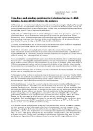
Part One: <strong>Removal</strong><br />
WARNING!<br />
READ YOUR WARRANTY FIRST!<br />
IF YOUR SCOPE IS STILL UNDER WARRANTEE AND YOU DO ANY<br />
DISASSEMBLY IT WILL VOID THE WARRANTY!<br />
It is not necessary to touch any computer board components except for the wires<br />
indicated! The oils <strong>and</strong> acids from your skin, <strong>and</strong> static electricity can ruin sensitive<br />
components! Please read this entire document BEFORE attempting any disassembly! If<br />
you are in the least bit wary or unsure <strong>of</strong> completing the operation, it is better to send<br />
the scope to <strong>Celestron</strong> <strong>and</strong> let them fix it!<br />
DISCLAIMER: Neither the author <strong>of</strong> this page nor <strong>Celestron</strong> are liable at any time for<br />
any damages incurred by following ANY instructions found on this page!<br />
In case you want to repair your telescope as described below, <strong>Celestron</strong> is <strong>of</strong>fering the<br />
azimuth lever as well as the spring clamp as spare parts. Please ask your dealer.<br />
1/10
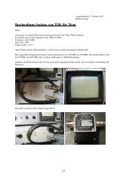
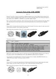
Take out the 5 allen head screws from the top base cover. Gently lift up. Position the cover as<br />
shown so you can have a look see.<br />
Pay attention to where the wiring is <strong>and</strong> the various tensions so you don’t rip anything up.<br />
2/10
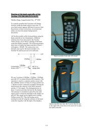
On mine I noticed that the factory assembler neglected to move the wire out <strong>of</strong> the way<br />
before securing the base top cover <strong>and</strong> pinched <strong>of</strong>f a bit <strong>of</strong> the insulation from the wire going<br />
up into the fork arm! Luckily it did not pinch all the way through to the wire itself. You may<br />
want to pay special attention to this during reassembly as there are wire on both sides going<br />
up into the fork arm to move out <strong>of</strong> the way before securing the base top cover!<br />
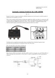
Once you have had a look. Disconnect the two wire connector from the position plates. Then<br />
gently pull on the wires going into the fork arm to take up the slack <strong>and</strong> give you a little room<br />
to set the BTC into a better position as shown.<br />
3/10
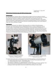
Once you have had a look. Disconnect the two wire connector from the position plates. Then<br />
gently pull on the wires going into the fork arm to take up the slack <strong>and</strong> give you a little room<br />
to set the BTC into a better position as shown.<br />
View from right with HC in back.<br />
4/10
Take the 4, #1 phillips head screws out <strong>of</strong> the position plates <strong>and</strong> remove the plates<br />
Remove the nut from the shaft. You will have to hold the bottom <strong>of</strong> the base as you turn the<br />
nut.<br />
5/10
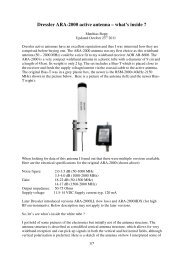
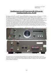
Now remove the large nut holding the upper assembly to the base. I used a 1 1/8”, 12 point<br />
socket to achieve this. Pay attention to the wire in the center <strong>of</strong> the shaft so as not to twist it<br />
<strong>of</strong>f. I lifted <strong>of</strong>f the socket <strong>and</strong> straightened out the wire at every turn! The crud you are seeing<br />
is due to the “locktite” (locking laquer). You might as well go get a bottle for reassembly as<br />
soon as you order your parts (s).<br />
Above photo thanks to Kevin Yahoo <strong>Nexstar</strong> <strong>GPS</strong> Group<br />
NOTE: Some have reported that too much loctite has been to the threads <strong>of</strong> some scopes as<br />
shown in the above photo. In such a case, the nut is not easily removed <strong>and</strong> the upper<br />
assembly does not just lift <strong>of</strong>f <strong>and</strong> alternate methods must be used.<br />
I recommend extreme caution <strong>and</strong> an extra set <strong>of</strong> h<strong>and</strong>s. Extra force may be required!<br />
6/10
Once you have removed the nut the upper assembly should come right <strong>of</strong>f. Take care in<br />
placement so as not to damage the roller bearings it rides on!<br />
You should now be looking at the azimuth drive gear. Remove the large nut <strong>and</strong> remove the<br />
gear assembly. This is a rather large nut <strong>and</strong> some <strong>of</strong> us may not have a tool large enough to<br />
remove it…BUT…<br />
7/10
If you have even a small vise, position as such <strong>and</strong> turn the base. Notice the weight <strong>of</strong> the<br />
base rides on the flat washer so that the vise will never touch the drive gear! Once the nut is<br />
free, take the base out <strong>of</strong> the vise <strong>and</strong> remove the nut with your fingers. Then the gear<br />
assembly will come right <strong>of</strong>f the shaft. This is a 1 3/4" nut <strong>and</strong> here also there is a possibility<br />
<strong>of</strong> too much loctite being used here. The nut <strong>and</strong> the subsequent bearing may be stuck!<br />
I recommend extreme caution <strong>and</strong> an extra set <strong>of</strong> h<strong>and</strong>s. Extra force may be required!<br />
Most likely you will now see what the problem is!<br />
8/10
Remove the 3 nuts from the tension adjuster.<br />
Remove the Clutch <strong>and</strong> go order the part!<br />
9/10
As for my feelings, it was an easy disassembly, but I don’t feel this kind <strong>of</strong> damage should<br />
have occurred from normal use, especially when the tension has never been adjusted!<br />
Place all <strong>of</strong> the parts in a clean environment until you get your new parts. I used the giant 80<br />
gallon trash bags <strong>and</strong> place a beach towel under the bag to keep out the light.<br />
WARNING!<br />
READ YOUR WARRANTY FIRST!<br />
IF YOUR SCOPE IS STILL UNDER WARRANTEE AND YOU DO ANY<br />
DISASSEMBLY IT WILL VOID THE WARRANTY!<br />
That being said, the non-warranty price quoted by <strong>Celestron</strong> Inc. USA for the parts are as<br />
follows: Azimuth Lever $21.00, Ring Clamp $<strong>11</strong>.00, S & H $5.00<br />
End <strong>of</strong> part one.<br />
Many thanks to Adrian for allowing me to post this excellent article on my Homepage.<br />
Best regards<br />
Matthias<br />
Email: dd1us@amsat.org<br />
Homepage: www.dd1us.de<br />
10/10