USER MANUAL - Videcon
USER MANUAL - Videcon
USER MANUAL - Videcon

You also want an ePaper? Increase the reach of your titles
YUMPU automatically turns print PDFs into web optimized ePapers that Google loves.
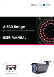
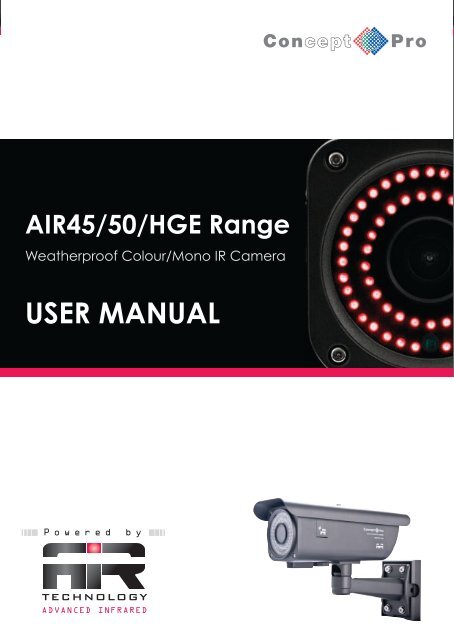
AIR45/50/HGE Range<br />
Weatherproof Colour/Mono IR Camera<br />
<strong>USER</strong> <strong>MANUAL</strong><br />
P o w e r e d b y<br />
TECHNOLOGY<br />
ADVANCED INFRARED
L<br />
U<br />
D<br />
R<br />
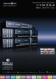
The Concept Pro AIR45 / 50 range are weatherproof IR cameras, suitable<br />
for monitoring areas in hostile conditions and in low light.<br />
3<br />
1<br />
2<br />
4<br />
7<br />
5<br />
8<br />
6<br />
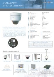
1 Fixing Bolt for Sunvisor<br />
2. Photo Sensor<br />
3. IR LED<br />
4. Sunvisor<br />
5 Mounting Bracket<br />
6 Bracket Adjustment<br />
7 External Lens Adjustment<br />
8 Service Video Output<br />
PACKING CONTENTS<br />
WALL SCREW<br />
X4<br />
FIXING PLATE<br />
X1<br />
FIXING PLATE<br />
LOCATING SCREW<br />
X2<br />
SERVICE VIDEO OUT<br />
CONNECTOR<br />
(AIR4526 MODEL ONLY)<br />
X1<br />
EASY FIT BNC CONNECTOR<br />
X1<br />
BRACKET/FIXING<br />
PLATE SCREW<br />
X4<br />
LENS ADJUSTMENT<br />
COVER SCREW<br />
X1<br />
ALLEN KEY<br />
X1<br />
EASY FIT POWER CONNECTOR<br />
X1<br />
<strong>USER</strong> <strong>MANUAL</strong><br />
LENS ADJUSTMENT<br />
TOOL<br />
X1<br />
<strong>USER</strong><br />
<strong>MANUAL</strong><br />
X1<br />
MOUNTING<br />
DRAWING PAPER<br />
X1<br />
OSD CABLE<br />
(AIR4526HG / 4527HG / 5026HG<br />
MODELS ONLY)<br />
X1<br />
ENT
CAUTION<br />
1. This installation should be made by a qualified service person and should abide to all local<br />
codes.<br />
2. In order to prevent electronic shock and/or destroy waterproof seals, do not loosen any<br />
screws on the camera body.<br />
3. Adjust the sunshield cover to avoid exposure of direct sunlight on the lens.<br />
4. Do not touch the front glass directly. If necessary, use a soft cloth moistened with alcohol to<br />
wipe off dust or debris.<br />
5. Avoid installation on a surface subjected to frequent vibration or shocks.<br />
6. Do not operate the camera beyond its temperature range or power source ratings.<br />
7. Should any damage or suspected damage occur, shutdown the power source, unplug and<br />
contact your service provider.<br />
8. Do not install the camera under unstable lighting conditions. Severe lighting change or<br />
flicker can cause the camera to work improperly.<br />
9. Never use the camera close to a gas or oil leak.<br />
10. Do not disassemble the camera.<br />
11. Do not drop the camera or subject the unit to physical shocks. Never keep the camera<br />
face to strong light directly, this can damage the CCD.<br />
12. Ensure all removable covers are replaced to protect the inner components.<br />
13. Do not install near devices which emit a strong electro-magnetic field.<br />
14. Use a dry or damp cloth only for cleaning.<br />
PLEASE FOLLOW THE ABOVE CAUTIONS – FAILURE TO DO SO MAY<br />
INVALIDATE THE WARRANTY OR CAUSE SERIOUS INJURY.<br />
Remark: Changes or modifications not expressly approved by the manufacturer can<br />
cause the camera to be damaged and become inoperable. This may invalidate the<br />
user warranty.
INSTALLATION<br />
Important: Ensure all cautionary procedures are observed during installation.<br />
It is recommended the camera is tested during the most demanding environmental conditions<br />
such as low light or bright sunlight to ensure continuity of effective CCTV monitoring. You may<br />
find the use of an ND filter helpful.<br />
Remove the camera unit carefully from the box, reserving the accessory contents in a<br />
safe place.<br />
FIXING TO A WALL<br />
• Use the supplied drill mounting<br />
template to mark the spacing<br />
for drilling.<br />
• Following drilling, securely<br />
attach the bracket and<br />
camera to the wall.<br />
MOUNTING TEMPLATE<br />
POSITIONING<br />
Point the Camera towards the intended<br />
area to be monitored.
CONNECTION<br />
BNC CONNECTOR<br />
POWER CONNECTOR<br />
PSU<br />
• Connect the video out port to your video cable<br />
running to the monitoring recorder.<br />
• Check the power supply is of the correct level<br />
and connect your power supply into the power<br />
port on the Camera.<br />
• View the picture on a monitoring device to<br />
check the power and video connection is<br />
working properly.<br />
Troubleshooting<br />
• Ensure all power and cable connections are correct with the Camera, DVR and Test monitor<br />
or Telemetry devices if used.<br />
• Power Voltage Check - Remove the OSD cover to see if the green correct power LED is lit. If<br />
there red LED is lit the power voltage is too high. If the yellow LED is lit the power voltage is<br />
not high enough. If there are no LEDs lit there is no power getting to the camera<br />
• If all power and cable connections are correct and the camera picture can not be produced or<br />
configured then contact your supplier for technical support.
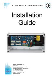
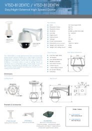
SERVICE VIDEO OUTPUT (AIR4026 MODEL ONLY)<br />
The Service Video Out panel contains a power indicator and test monitor connection for<br />
ease of adjusting the camera settings during installation.<br />
1 2 3<br />
PO<br />
PN<br />
PL<br />
VIDEO<br />
SERVICE VIDEO OUTPUT CABLE<br />
TEST MONITOR<br />
AIR4526<br />
4<br />
The power indicator LEDs display the power supply being fed into the camera and whether it<br />
is too high, low or correct.<br />
1. "PO": Red LED - Voltage is too high<br />
2. "PN": Green LED - Voltage is correct<br />
3. "PL": Yellow LED - Voltage is too low<br />
4. Extra video out for testing monitor - Attach your Video test monitor with the service video<br />
cable enclosed in your camera box. The camera footage will appear on your test monitor<br />
and zoom/focus adjustments can be carried out as the installation requires.<br />
SEE OVERLEAF FOR AIR-HGE ON SCREEN DISPLAY<br />
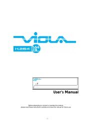
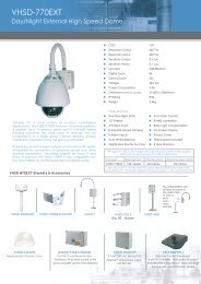
EXTERNAL LENS ADJUSTMENT<br />
1<br />
2<br />
1 Open the lens adjuster cover and<br />
adjust focus and zoom. Loose the<br />
screw on the lens adjuster cover.<br />
2. Lens Adjustment Tool<br />
3 Focus and Zoom Adjustments<br />
A Zoom Wide / Narrow<br />
Focus Near / Far<br />
3<br />
A
L<br />
U<br />
D<br />
R<br />
ON SCREEN DISPLAY (OSD) (AIR4526HGE / 4527HGE / 5026HGE MODELS ONLY)<br />
The Service Video Out panel contains a power indicator and test monitor connection for<br />
ease of adjusting the camera settings during installation.<br />
1 2 3<br />
PO<br />
PN<br />
PL<br />
VIDEO<br />
ENT<br />
OSD OUTPUT CABLE<br />
TEST MONITOR<br />
4<br />
AIR-HGE MODELS ONLY<br />
The power indicator LEDs display the power supply being fed into the camera and whether it<br />
is too high, low or correct.<br />
1. "PO": Red LED - Voltage is too high<br />
2. "PN": Green LED - Voltage is correct<br />
3. "PL": Yellow LED - Voltage is too low<br />
4. Extra video out and OSD Connector - Attach your Video test monitor with the service video<br />
cable enclosed in your camera box. The camera footage will appear on your test monitor<br />
and zoom/focus adjustments can be carried out as the installation requires.<br />
OSD Controller<br />
U<br />
1) Press “U” to navigate upwards<br />
2) Press “D” to navigate downwards<br />
L<br />
ENT<br />
R<br />
3) Press “L” to navigate left<br />
4) Press “R” to navigate right<br />
D<br />
5) Press “ENT” to open menu/sub-menu<br />
(AIR4526HGE / 4527HGE / 5026HGE MODELS ONLY)
LANGUAGE<br />
ENGLISH / SPANISH / PORTUGUESE /<br />
FRENCH / GERMAN / CHINESE /<br />
JAPANESE / RUSSIAN<br />
LENS<br />
<strong>MANUAL</strong><br />
AUTO TYPE DC<br />
MODE AUTO, OPEN, CLOSE<br />
SPEED 0~255<br />
SHUTTER / AGC<br />
AUTO<br />
<strong>MANUAL</strong><br />
HIGH LUMINANCE<br />
MODE<br />
SHUT+AUTO IRIS, AUTO IRIS<br />
BRIGHTNESS 0~255<br />
LOW LUMINANCE<br />
MODE<br />
AGC, OFF<br />
BRIGHTNESS 0.25~1.00<br />
MODE<br />
SHUT+AGC<br />
SHUTTER 1/50~1/10000<br />
AGC 6.00~44.80<br />
WHITE BALANCE<br />
ATW<br />
SPEED 0~255<br />
DELAY CNT 0~255<br />
ATW FRAME X0.50~X2.00<br />
ENVIRONMENT INDOOR/OUTDOOR<br />
PUSH LOCK<br />
<strong>MANUAL</strong> LEVEL 0~255<br />
ANTI CR<br />
<strong>USER</strong> 1 B-GAIN 0~255<br />
R-GAIN 0~255<br />
<strong>USER</strong> 2 B-GAIN 0~255<br />
R-GAIN 0~255<br />
PUSH
PICT ADJUST<br />
MIRROR<br />
BRIGHTNESS<br />
CONTRACT<br />
SHARPNESS<br />
HUE<br />
GRAIN<br />
OFF/ON<br />
0~255<br />
0~255<br />
0~255<br />
0~255<br />
0~255<br />
NR<br />
NR MODE<br />
Y LEVEL<br />
C LEVEL<br />
Y/C, C, Y, OFF<br />
0~15<br />
0~15<br />
BACKLIGHT<br />
OFF/BLC/HLC<br />
ATR<br />
OFF<br />
ON LUMINANCE LOW, MID, HIGH<br />
CONTRAST LOW, MIDLOW, MID,<br />
MIDHIGH, HIGH
PRIVACY<br />
OFF<br />
ON AREA SEL 1~4<br />
TOP 0~288<br />
BOTTOM 0~288<br />
LEFT 0~468<br />
RIGHT 0~468<br />
COLOUR 1~8<br />
TRANSP 0.00~1.00<br />
MOSIAC OFF/ON<br />
MOTION DETECTION<br />
OFF<br />
ON DETECT SENSE 0~127<br />
BLOCK DISPLAY OFF/ON/ENABLE/<br />
SELECT AREA<br />
MONITOR AREA OFF/ON<br />
AREA SELECT 1~4<br />
TOP 0~288<br />
BOTTOM 0~288<br />
LEFT 0~288<br />
RIGHT 0~288<br />
CAMERA ID<br />
OFF<br />
ON<br />
OPENS VIRTUAL KEYBOARD<br />
SAVE ALL<br />
IMPORTANT - PLEASE NOTE:<br />
When all configurations have been made select SAVE<br />
ALL at the bottom of the OSD before exiting
DIMENSIONS<br />
100mm(3.94”)<br />
40mm(1.57”)<br />
300mm(11.81”)<br />
219mm(8.62”)<br />
85mm(3.35”) 97mm(3.85”)<br />
319mm(12.56”)
AIR-IR<br />
IR LAMPS<br />
Extend the IR range up to 80m with AIR-IR.<br />
* Lens should be used at 6mm or above to achieve even illumination<br />
302.2mm(11.89”)<br />
300mm(11.81”)<br />
85mm(3.35”)<br />
97mm(3.85”)<br />
219mm(8.62”)<br />
40mm(1.57”)<br />
319mm(12.56”)
ITEM<br />
AIR4527HGE<br />
AIR5026HGE<br />
Type<br />
Signal System<br />
Pick Up Device<br />
Picture Elements<br />
Resolution<br />
Min Illumination<br />
Vertical Frequency<br />
Horizontal Frequency<br />
Clock Frequency<br />
Scanning System<br />
S/N Ratio<br />
Electronic Shutter<br />
Colour/Monochrome (Removable IR Cut Filter)<br />
PAL<br />
1/3" Sony Colour High Resolution CCD<br />
976H×582V<br />
650TVL<br />
0Lux (60Pieces IR LED ON)<br />
50Hz<br />
15.625KHz<br />
PAL:36.00MHz<br />
2:1 Interlace<br />
≥52dB<br />
1/50-1/100,000s<br />
Lens<br />
White Balance<br />
Back Light<br />
Auto Gain Control<br />
GAMMA<br />
Video Out-put<br />
9-22mm Varifocal Auto iris IR Lens<br />
Selectable<br />
Selectable<br />
Selectable<br />
0.45<br />
1V p-p,75Ω<br />
6-50mm Varifocal Auto Iris IR Lens<br />
Power Supply<br />
Current Consumption<br />
DC12V ±10%/AC24V±10%<br />
DC:730~750mA/AC:510~530mA (Max)<br />
IR Effect Distance<br />
45~50m (147.5~163.9ft) (Outdoor)<br />
50~55m (163.9~180.3ft) (Outdoor)<br />
Dimension<br />
Weight<br />
Storage Temperature<br />
Operating Temperature<br />
319x219x100mm<br />
2.5Kg<br />
-30°+60° (-22°+140°)<br />
-30°+40° (-22°+104°)<br />
Design and specification are subject to change without notice.
ITEM<br />
AIR4526<br />
AIR4526HGE<br />
Type<br />
Signal System<br />
Pick Up Device<br />
Colour/Monochrome (Removable IR Cut Filter)<br />
PAL<br />
1/3" Sony Colour High Resolution CCD<br />
Picture Elements<br />
Resolution<br />
795H x 596V<br />
520TVL<br />
976H x 582V<br />
650TVL<br />
Min Illumination<br />
Vertical Frequency<br />
Horizontal Frequency<br />
0Lux (60Pieces IR LED ON)<br />
50Hz<br />
15.625KHz<br />
Clock Frequency<br />
PAL:28.375MHz<br />
PAL:36.00MHz<br />
Scanning System<br />
2:1 Interlace<br />
S/N Ratio<br />
≥50dB<br />
≥52dB<br />
Electronic Shutter<br />
Lens<br />
1/50-1/100,000s<br />
3.5-8mm IR Varifocal Lens<br />
White Balance<br />
Back Light<br />
Auto Gain Control<br />
AUTO Tracking<br />
ON<br />
ON<br />
Selectable<br />
Selectable<br />
Selectable<br />
GAMMA<br />
Video Out-put<br />
Power Supply<br />
0.45<br />
1V p-p,75Ω<br />
DC12V ±10%/AC24V±10%<br />
Current Consumption<br />
DC:600mA/AC480mA (Max)<br />
DC:620mA/AC500mA (Max)<br />
IR Effect Distance<br />
Dimension<br />
Weight<br />
Storage Temperature<br />
Operating Temperature<br />
30~35m (98.4~114.8ft) (Outdoor)<br />
319x219x100mm<br />
2.5Kg<br />
-30°+60° (-22°+140°)<br />
-30°+40° (-22°+104°)<br />
Design and specification are subject to change without notice.
AIR CAMERA RANGE<br />
AIR15 Range<br />
18 IR LEDs<br />
420 TVL / 520 TVL Options<br />
3.6mm / 6mm Fixed Lens Options<br />
182 x 70 x 81mm (WxHxD)<br />
AIR30 Range<br />
42 IR LEDs<br />
Varifocal Lens Options<br />
Service Video Output Option<br />
On Screen Display Option<br />
External Lens / Zoom Adjustments<br />
202 x 85 x 118mm (WxHxD)<br />
AIR-IR<br />
It is possible to extend the IR<br />
range of the AIR 45/50 range<br />
with an easy to attach bolt-on<br />
twin IR lamp. The AIR-IR twin<br />
lamp allows the camera unit to<br />
view up to 80m.