User Manual - Videcon
User Manual - Videcon
User Manual - Videcon

Create successful ePaper yourself
Turn your PDF publications into a flip-book with our unique Google optimized e-Paper software.
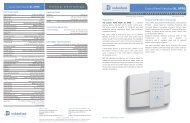
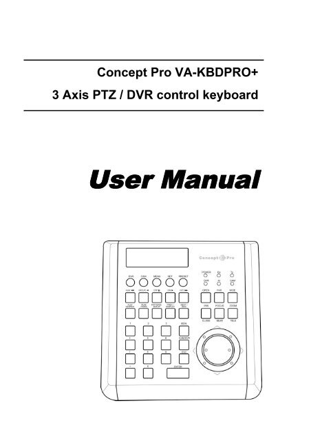
Concept Pro VA-KBDPRO+<br />
3 Axis PTZ / DVR control keyboard<br />
<strong>User</strong> <strong>Manual</strong>
Contents<br />
Key features 1<br />
Example System configuration 1<br />
Operation modes 2<br />
Getting started 2<br />
Programming the keyboard<br />
Matrix setup 3<br />
DVR setup 3<br />
Camera Setup 4<br />
Key buzzer 5<br />
Key ID 5<br />
Key level 5<br />
Monitor range 5<br />
Camera range 5<br />
DVR range 5<br />
Change default password 5<br />
Reset factory defaults 5<br />
Keyboard operation<br />
CAM mode 6<br />
DVR mode 7<br />
DVR / AI mode 7
Key features<br />
Flexible configuration<br />
The VA-KBDPRO+ supports multiple telemetry protocols for compatibility with a wide range of PTZ devices.<br />
Protocols and baudrates can be set globally or individually for each PTZ ID<br />
DVR control<br />
The VA-KBDPRO+ is designed to control all the main functions of one or more Concept Pro VXM4 DVR systems<br />
Matrix support<br />
Concept Pro matrix systems can be used with the VA-KBDPRO+ for full camera / VXM4 input switching and<br />
monitor output control<br />
Mixed mode (Associate ID) control<br />
The VA-KBDPRO+ can be programmed to control specific PTZ IDs depending on which VXM4 ID and input<br />
channel is selected<br />
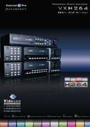
Example system configuration<br />
1
Operation modes<br />
Getting started<br />
The VA-KBDPRO+ has 3 operating modes which<br />
are used depending on the system configuration<br />
Please note: all necessary connections must be<br />
made before applying power to the VA-KBDPRO+<br />
1. CAM mode<br />
In CAM mode, the VA-KBDPRO+ functions as a<br />
standard PTZ telemetry controller.<br />
The operator can select individual telemetry<br />
devices to control and can also access all features<br />
of those telemetry devices, such as presets,<br />
patterns, groups and menu setup.<br />
If a Concept Pro matrix is connected, as each<br />
camera ID is selected, the matrix will<br />
automatically switch to the corresponding input.<br />
Depending on the matrix configuration, multiple<br />
monitor outputs can also be controlled.<br />
2. DVR mode<br />
In DVR mode, the VA-KBDPRO+ is used to<br />
control all the key functions of one or more<br />
Concept Pro VXM4 digital recorders.<br />
The operator can select individual VXM4s and<br />
select channels, choose display modes, playback<br />
footage or setup the DVR<br />
If a Concept Pro matrix is connected, as each<br />
DVR ID is selected, the matrix will automatically<br />
switch to the corresponding input.<br />
Depending on the matrix configuration, multiple<br />
monitor outputs can also be controlled.<br />
3. DVR / AI mode<br />
In DVR / AI mode, the VA-KBDPRO+ can control<br />
telemetry devices and VXM4 channel selection.<br />
The operator chooses a DVR ID and a particular<br />
channel input to view full screen, and the VA-<br />
KBDPRO+ automatically selects the associated<br />
speed dome ID. This can then be controlled<br />
directly from the keyboard rather than the DVR<br />
front panel.<br />
If a Concept Pro matrix is connected, as each<br />
DVR ID is selected, the matrix will automatically<br />
switch to the corresponding input.<br />
Depending on the matrix configuration, multiple<br />
monitor outputs can also be controlled.<br />
Full DVR / AI mode operation must be<br />
programmed through the keyboard setup menu<br />
and is described on page 3<br />
• Connect the supplied CAT5 lead between the<br />
junction box and the VA-KBDPRO+<br />
• Using the 5 way multi plug, connect ‘-’ to the<br />
negative side of the telemetry line and ‘+’ to the<br />
positive side<br />
• If VXM4 control is required, RS485 telemetry<br />
must be connected to the VXM4 via its RS232<br />
port using a VXM4-RS232CONV serial converter<br />
• The RS232 connections on the VA-KBDPRO+<br />
junction box are reserved and should not be used<br />
• Connect power to the VA-KBDPRO+. The VA-<br />
KBDPRO+ performs its self test and displays<br />
the startup screen<br />
VER30<br />
System Keyboard<br />
Press the MENU key to begin normal operation<br />
– the default operation mode is CAM for normal<br />
control of PTZ devices<br />
MONITOR CAM<br />
001 001<br />
2
Programming the keyboard<br />
To access the keyboard setup, press the MENU<br />
key – the keyboard will prompt for a password<br />
PASSWORD:<br />
**********<br />
Enter the default password of 9876543210 and<br />
press ENTER. The setup menu is displayed<br />
SET MATRIX:<br />
>SET_PROTOCOL><br />
To navigate the menu, move the joystick up/down<br />
pressing ENTER to select menu items or ESC to<br />
exit menu items<br />
DVR setup<br />
SET BAUDRATE<br />
Enter the keyboard setup menu and use the<br />
joystick to highlight SET DVR. The cursor flashes<br />
next to SET_BAUDRATE<br />
SET DVR:<br />
>SET_BAUDRATE><br />
Press ENTER and then twist the joystick left /<br />
right to select the required baudrate. Press<br />
ENTER to accept the new baudrate setting or<br />
ESC to discard. If using a Concept Pro VXM4, the<br />
baudrate should be set to 9600<br />
Matrix setup<br />
SET PROTOCOL<br />
Enter the keyboard setup menu and use the<br />
joystick to highlight SET MATRIX. The cursor<br />
flashes next to SET_PROTOCOL<br />
SET MATRIX:<br />
>SET_PROTOCOL><br />
Press ENTER and then twist the joystick left /<br />
right to select the required protocol. Press ENTER<br />
to accept the new protocol setting or ESC to<br />
discard. If using a Concept Pro matrix system, the<br />
protocol should be set to T_VC<br />
Matrix setup<br />
SET BAUDRATE<br />
Enter the keyboard setup menu and use the<br />
joystick to highlight SET MATRIX. The cursor<br />
flashes next to SET_PROTOCOL. Twist the<br />
joystick right to change the display to<br />
SET_BAUDRATE<br />
SET MATRIX:<br />
>SET_BAUDRATE><br />
Press ENTER and then twist the joystick left /<br />
right to select the required baudrate. Press<br />
ENTER to accept the new baudrate setting or<br />
ESC to discard. If using a Concept Pro matrix<br />
system, the baudrate should be set to 9600<br />
DVR setup<br />
SET ASSOCIATE<br />
Enter the keyboard setup menu and use the<br />
joystick to highlight SET DVR. The cursor flashes<br />
next to SET_BAUDRATE. Twist the joystick right<br />
to change the display to SET_ASSOCIATE<br />
SET DVR:<br />
>SET_ASSOCIATE><br />
Press ENTER to display the set associate ID<br />
screen<br />
ID:01<br />
CH:01<br />
OUT:0001<br />
CAM:0001<br />
ID:01 / OUT:0001 – If a Concept Pro matrix is<br />
connected, these two values determine which<br />
matrix channel (OUT) is switched for a particular<br />
DVR (ID).<br />
For example, if a VXM4 with an ID of 7 is<br />
connected to matrix channel 2, set ID to 07 and<br />
OUT to 0002<br />
CH:01 / CAM:0001 – if PTZ devices are<br />
connected to the DVR, these values specifiy<br />
which PTZ ID is connected to which DVR input<br />
channel.<br />
For example, if a speed dome with ID 32 is<br />
connected to DVR input 7, set CH to 07 and CAM<br />
to 0032<br />
Use the joystick to select the value and enter a<br />
new value using the numeric keypad. Press<br />
ENTER to save changes.<br />
3
Camera setup<br />
SET PROTOCOL<br />
Enter the keyboard setup menu and use the<br />
joystick to highlight SET CAMERA. The cursor<br />
flashes next to SET_PROTOCOL<br />
SET CAMERA:<br />
>SET_PROTOCOL><br />
Press ENTER to display the SET PROTOCOL<br />
screen<br />
ALL :>VC<br />
0001:>VC<br />
Protocols can be set globally or for each individual<br />
channel.<br />
To set protocol globally, move the joystick<br />
up/down so that the cursor flashes on the ‘>’<br />
symbol next to ALL :<br />
ALL :VC<br />
0001:>VC<br />
Twist the joystick left / right to select the required<br />
protocol and press ENTER to confirm. Press ESC<br />
to return to the SET CAMERA menu<br />
To set protocol for each individual channel, move<br />
the joystick up/down so that the cursor flashes on<br />
the ‘0’ of 0001:<br />
ALL :>VC<br />
001:>VC<br />
Use the numeric keypad to enter the 4 digit<br />
camera ID to change, eg ‘0002’. The cursor now<br />
moves to protocol selection<br />
ALL :>VC<br />
0002:VC<br />
Twist the joystick left / right to select the required<br />
protocol and press ENTER to confirm. The ID<br />
automatically advances to the next number.<br />
Continue setting up protocols for all camera IDs<br />
as required and then press ESC to return to the<br />
SET CAMERA menu<br />
Camera setup<br />
SET BAUDRATE<br />
Enter the keyboard setup menu and use the<br />
joystick to highlight SET CAMERA. The cursor<br />
flashes next to SET_PROTOCOL. Twist the<br />
joystick right to change the display to<br />
SET_BAUDRATE<br />
SET CAMERA:<br />
>SET_BAUDRATE><br />
Press ENTER to display the SET BAUDRATE<br />
screen<br />
ALL :>9600<br />
0001:>9600<br />
Baudrates can be set globally or for each individual<br />
channel.<br />
To set baudrate globally, move the joystick<br />
up/down so that the cursor flashes on the ‘>’<br />
symbol next to ALL :<br />
ALL :9600<br />
0001:>9600<br />
Twist the joystick left / right to select the required<br />
baudrate and press ENTER to confirm. Press ESC<br />
to return to the SET CAMERA menu<br />
To set baudrate for each individual channel, move<br />
the joystick up/down so that the cursor flashes on<br />
the ‘0’ of 0001:<br />
ALL :>9600<br />
001:>9600<br />
Use the numeric keypad to enter the 4 digit<br />
camera ID to change, eg ‘0002’. The cursor now<br />
moves to baudrate selection<br />
ALL :>9600<br />
0002:9600<br />
Twist the joystick left / right to select the required<br />
baudrate and press ENTER to confirm. The ID<br />
automatically advances to the next number.<br />
Continue setting up baudrates for all camera IDs<br />
as required and then press ESC to return to the<br />
SET CAMERA menu<br />
4
Key Buzzer<br />
The VA-KBDPRO+ has an internal key press<br />
buzzer which can be enabled or disabled as<br />
required. Enter the keyboard setup menu and use<br />
the joystick to highlight KEY BUZZER. The cursor<br />
flashes next to ENABLE BEEP<br />
KEY BUZZER:<br />
ENABLE BEEP<br />
Twist the joystick left / right to toggle between<br />
ENABLE BEEP / DISABLE BEEP and press<br />
ENTER to confirm<br />
Set Key ID<br />
When multiple keyboards are used on the same<br />
matrix system, each keyboard must have a unique<br />
ID. Enter the keyboard setup menu and use the<br />
joystick to highlight SET KEY ID.<br />
SET KEY ID:<br />
0100-239********<br />
Use the numeric keypad to enter the factory reset<br />
password of 0123456789 and press ENTER<br />
5
Keyboard operation<br />
CAM mode<br />
Please note that all the operation examples given<br />
here are for the Concept Pro VHSD-8XX series of<br />
speed domes. For any other type of PTZ<br />
equipment, reference should be made to its user<br />
manual for the appropriate command sequences.<br />
To place the keyboard in to CAM mode, press the<br />
CAM button.<br />
MONITOR CAM<br />
001 001<br />
To select a particular camera ID, press<br />
CAM/DVR – XXX – ENTER<br />
Where XXX is a numeric camera ID<br />
To control the selected camera, move the joystick<br />
up/down/left/right – the further the joystick is<br />
moved, the faster the movement. Twist the<br />
joystick clockwise to zoom in and anti-clockwise<br />
to zoom out. The zoom level can also be<br />
controlled by pressing the WIDE and TELE buttons<br />
Managing presets<br />
To program a preset position, move the speed<br />
dome to the desired scene and zoom level and<br />
press SET – XXX – ENTER, where XXX is a<br />
preset position between 1 and 128 (but note that<br />
preset 95 is reserved and cannot be used)<br />
To move the speed dome to a preset position<br />
that’s already been programmed, press PRESET –<br />
XXX – ENTER where XXX is a preset position<br />
between 1 and 128 (but note that preset 95 is<br />
reserved and cannot be used)<br />
To clear a preset position from the speed dome<br />
memory, press ESC – XXX – ENTER where XXX<br />
is a preset position between 1 and 128 (but note<br />
that preset 95 is reserved and cannot be used)<br />
Using the speed dome setup menu<br />
To enter the speed dome menu, press<br />
PRESET – 95 – ENTER<br />
To choose a menu item or change settings within<br />
a menu item, move the joystick up / down<br />
To enter a menu item or confirm a new setting,<br />
press NEAR<br />
To exit a menu item or cancel a new setting,<br />
press FAR<br />
Please refer to the manual supplied with the speed<br />
dome for a detailed explanation of the menu setup<br />
procedures<br />
Additional operations if a matrix is connected<br />
When a particular camera ID is selected on the<br />
keyboard, the appropriate input on the matrix is<br />
automatically switched.<br />
To start / stop a sequence, press the RUN key<br />
To switch to the next camera, press the NEXT key<br />
To switch to the previous camera, press the<br />
PREV key<br />
When multiple monitors are connected, individual<br />
cameras can be displayed on different monitors.<br />
To select the required monitor, press<br />
MON – XXX – ENTER<br />
And then select the required camera to be<br />
displayed on that monitor by pressing<br />
CAM/DVR – XXX – ENTER<br />
Running pattern tours, variable speed<br />
tracking and group functions<br />
To start a pattern tour, press PRESET –13X –<br />
ENTER, where X is a predefined pattern tour<br />
number between 1 & 4<br />
To start a VST function, press PRESET –14X –<br />
ENTER, where X is a predefined VST function<br />
between 1 & 8<br />
To start a group, press PRESET –15X – ENTER,<br />
where X is a predefined group between 1 & 8<br />
6
Keyboard operation<br />
DVR mode<br />
Please note that this keyboard can only control the<br />
Concept Pro VXM4 range of DVRs<br />
To place the keyboard in to DVR mode, press the<br />
DVR button repeatedly until only the yellow DVR LED<br />
is lit<br />
MONITOR DVR<br />
001 001<br />
To select a particular DVR ID, press<br />
CAM/DVR – XXX – ENTER<br />
Where XXX is a numeric DVR ID<br />
To select channels full screen, press XX – ENTER,<br />
where XX is a channel number between 1 & 16.<br />
The SEARCH, PANIC, SETUP, DISPLAY and SEQ<br />
buttons control the relevant functions of the VXM4<br />
To navigate through the VXM4 on screen displays (eg<br />
during Setup and Search modes), move the joystick<br />
up / down / left / right and press ENTER and ESC to<br />
select or cancel items respectively.<br />
To enter passwords (eg, during Setup and Search<br />
modes), the keyboard must be switched to numeric<br />
entry mode by pressing the * key<br />
For example, when the VXM4 prompts for a<br />
password, the following key sequence should be used<br />
* - XXXX - * - ENTER, where XXXX is the password<br />
Note – the * key must be pressed after the password<br />
is entered to switch the keyboard back to normal<br />
operation<br />
When the VXM4 is in playback mode, the five<br />
playback buttons and / or the joystick can be used to<br />
control playback as follows:<br />
Select forward play – move the joystick right or press<br />
►<br />
Select reverse play – move the joystick left or press<br />
◄<br />
Pause playback – press<br />
װ Increase forward / decrease reverse play speed –<br />
press Additional ►► or operations twist the joystick if a matrix right is connected<br />
Decrease When a particular forward VXM4 / increase ID is reverse selected play on speed the –<br />
press keyboard, ◄◄ the or twist appropriate the joystick input left on the matrix is<br />
automatically switched according to the DVR / Set<br />
Associate programming (page 3).<br />
When multiple monitors are connected, individual<br />
VXM4s can be displayed on different monitors.<br />
To select the required monitor, press<br />
MON – XXX – ENTER<br />
And then select the required VXM4 to be displayed<br />
on that monitor by pressing<br />
CAM/DVR – XXX – ENTER<br />
7<br />
Keyboard operation<br />
DVR / AI mode<br />
Please note that this keyboard can only control the<br />
Concept Pro VXM4 range of DVRs.<br />
In DVR/AI mode only individual channels can be<br />
selected full screen. For full control of a VXM4,<br />
the standard DVR mode should be used (see<br />
opposite)<br />
To place the keyboard in to DVR/AI mode, press<br />
the DVR button repeatedly until both the yellow<br />
DVR and green AI LEDs are lit<br />
DVR:001 CH:01<br />
MON:001 PTZ:001<br />
To select a particular DVR ID, press<br />
CAM/DVR – XXX – ENTER<br />
Where XXX is a numeric DVR ID<br />
To display an individual channel of the selected<br />
DVR full screen and take control of the associated<br />
speed dome, press XX – ENTER, where XX is a<br />
channel number between 1 & 16.<br />
As each channel is selected full screen, the PTZ<br />
value automatically changes according to the DVR<br />
/ Set Associate programming (page 3)<br />
Full control of the associated speed dome is then<br />
available, including programming and recalling<br />
presets, starting groups, tours, etc.<br />
Additional operations if a matrix is connected<br />
When a particular VXM4 ID is selected on the<br />
keyboard, the appropriate input on the matrix is<br />
automatically switched according to the DVR / Set<br />
Associate programming (page 3).<br />
When multiple monitors are connected, individual<br />
VXM4s can be displayed on different monitors.<br />
To select the required monitor, press<br />
MON – XXX – ENTER<br />
And then select the required VXM4 to be displayed<br />
on that monitor by pressing<br />
CAM/DVR – XXX – ENTER