Manual - Building Block Video CCTV
Manual - Building Block Video CCTV
Manual - Building Block Video CCTV
- No tags were found...

Create successful ePaper yourself
Turn your PDF publications into a flip-book with our unique Google optimized e-Paper software.
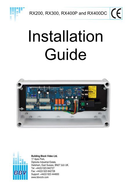
Rx200 mk2AC Left/Right/Wipe/Lights/Wash or Autopan, software Random PanUNPACKINGInspect the packaging for signs of damage. If damage has occurred, advise the carriers and or the suppliersimmediately. Unpack the receiver carefully and check that all the items are present and correct.SAFETY PRECAUTIONSAll normal safety precautions as laid down by British Standards and the Health and Safety at Work Actshould be observed and servicing should be referred to qualified service personnel.Rx200 TECHNICAL SPECIFICATIONPower Requirements:Maximum Load:Receiver Current Draw:Fuse:230 volts 50/60Hz (options are available for 24Vac and 110Vac supply)IEC connector provided (screw terminals with 24Vac supply option)5 amp at 230 volts6VA maximumTransformer contains a none resetting thermal fuse in series with theprimary windings. If the transformer overheats, the fuse will protect the unitby going open circuit, removing power from the transformer.F2: Auxiliary output fuseSupply Output Fuse F2230 230 5A T230 24 315mA T110 110 5A T110 24 630mA T24 24 5A TOutputs:5 single-pole changeover relays (snubbed):1. LEFT PAN MOTOR2. RIGHT PAN MOTOR3. WIPER4. WASHER OR AUTOPAN (switch selectable)5. LIGHTSFacilities/Options:Telemetry Signals:Auto-Iris Output:<strong>Video</strong> Input:<strong>Video</strong>Output:Unit auto-tunes to the coaxial telemetry signalLED readout for continual system statusDiagnostic test button (SW8) activates each function for two seconds in turn; seeTable for test sequences<strong>Video</strong> launch amplifier provided with Gain and Lift controlsCamera power outlet providedColour-coded outlets: Live, Neutral and Earth24-volt output option available from factory; plugs into J5 (pre wired)Software Random Pan – doesn’t require autopan card in head.(a) Up the co-ax telemetry signals, designed to operate over 250M of RG59/500MCT125 co-ax; or (b) Twisted-pair 20mA loop (1200,E,8,1)Returns to original setting 15 seconds after key release.Level programmable from keypad.To drive override input for cosmicar, or seiko style lens1v p-p 75R Terminated Input via BNC socket1v p-p to 4v p-p 75R Impedance via BNC socketPCB Size: Width: 108 mm overall Boxed size: Width: 190mmLength: 203 mm without IEC insertedLength: 380mmHeight: 38 mm above PCBHeight: 130mmPCB Weight: 0.4 kg Boxed Weight: 2.5kgTelemetry Receiver Installation HandbookRx200mk22 July 2004 Rev6Page_3
WAGO CONNECTERSThe WAGO series 256 PCB terminal block is a simple-to-use method of attachingcables to PCBs quickly and easily. The correct method of attachment is as follows:1. Use only cable between 0.08 and 2.5 mm²2. Strip the cable to a length of 5 to 6 mm (0.23 in)3. Press down the relevant terminal block lever with a screwdriver4. Insert wire5. Remove screwdriverDetachment of wires is the reverse procedure of steps 3 to 5, ensuring that power isdisconnected before startingCABLING RECOMMENDATIONS FOR RX RANGE OF RECEIVERSAlthough BBV do not specify any particular type, manufacturer or supplier of cables,the following ESD Electronic Services (01279 626777) cables have been usedsuccessfully for production and testing:ESD Part Number:Description:071775GOutput Cable(100 m) 18-core 16/0.2mm PVC insulated/PVC sheathed cableRated at 440 volts AC rms at 1600 HzDEF 61-12 current rating per core 2.5 ampMaximum operating temperature: 70 degrees Celsius0222586GCo-Ax Cable (Minimum Specification)(100 m) RG59B/U ESD radio frequency co-ax cable to BS2316 and MIL-C-171/0.58mm copper-covered steel wire conductor with solid polythene dielectric,bare copper wire braid and PVC sheathCharacteristic impedance: 75 OhmCapacitance: 22pF/ft020966D Orange Coloured Lights Output Cable (1000 w)(100 m) 3183Y PVC Insulated 3 core cable1.25mm² 40/0.2mm annealed copper conductorCurrent rating: 13 amp0140467H20mA Twisted Pair Cable (Minimum Specification)(100 m) British Telecom Spec. CW 13082-core 1/0.5mm PVC insulatedMaximum conductor resistance at 20 degrees Celsius: 97.8 ohms/KmTelemetry Receiver Installation HandbookRx200mk22 July 2004 Rev6Page_4
Rx200 INSTALLATION INSTRUCTIONSThe Rx200 requires all connections to the PCB to be made by the installer and via terminal blocks or by plugand socket. These connections are: power, video in, video out, and pan or auxiliary outputs. See Table forthe correct connections.The Rx200 is normally supplied pre-configured to suit the application for which it is intended, and this will beeither to control a mains-operated panning head or other equipment, or to control a 24-volt panning head.The unit is suitable for 230 volt mains operation. As a factory fitted option, the receiver can be supplied tooperate from 24Vac or 110Vac. This option must be specified at time of order.For mains-voltage panning heads, the 110Vac or 230Vac supply is made via the IEC socket J4 .(Note - for mains operations, J5 is supplied with a header which links Pins 1 to 4 and Pins 3 to 6. )When using 24Vac heads, if the receiver is operating from a 110Vac or 230Vac supply either a 230/24VacKit or 110/24Vac Kit is used. The jumper fitted to J5 is removed and the plug supplied with the kit isconnected to J5. Fuse F2 is changed to the value shown in the table on 2.Receivers operating from 24Vac can only operate 24Vac heads. No kit is required.When operating from a 24Vac supply, power connection is by means of a screw terminal replacing the IECsocket.An 8 way DIL switch is provided allowing various options to be set as follows:-SW1UnusedSW2Controls auto-iris remote control featuresON Cosmicar lens, 2.5 - 5.5 voltsOFF Seiko/<strong>Video</strong> Technical lens, 2.5 - 12 voltsSW3 and SW4 Select between WASHER or AUTOPANSW3 SW4 FunctionON ON WASHEROFF OFF AUTOPANSW5,6,7 UnusedSW8 Start receiver self test, see page 5.Two L.E.D.'s (Error and Cable) are mounted on-board to give simple system status information. Theirfunctions are as follows:-Cable LEDRegular Blinking - Telemetry and Sync signals OKBlinking but mainly ON - No telemetry information from the transmitterBlinking but mainly OFF - No sync information from the cameraError LEDOn - Transmission error (e.g. framing error, parity error)Both LED'sOff - No power, or major PCB errorAs all BBV equipment is designed to auto-tune and compensate for any discrepancies in the transmittersignal, there are no further adjustments that need to be made.Random PanThe Random Pan feature allows the receiver to drive the head in a left or right direction at random for arandom time. The head will pause for a random time between movements. Over a period of time, the headwill move between the right and left end stops. This feature does not require an autopan card to be fitted tothe head. The Random Pan is started by issuing a PATROL 1 command from the telemetry controller. Thekey strokes required will vary depending upon the model of controller. Please refer to the controllerhandbook for details.Telemetry Receiver Installation HandbookRx200mk22 July 2004 Rev6Page_5
NEUTRALSW1 UNUSEDSW8(on/off) Start Self Test - LEFT,RIGHT,WIPE,WASH/AUTOPAN,LIGHTS,IRIS OPEN,CLOSESW2 Iris OverrideON = 2.5 - 5.5V, OFF = 2.5 - 12VSW3/SW4 Aux selectionFunction SW3 SW4WASHER ON ONAUTOPAN OFF OFFSW8 ON = SELF TESTSW5,6,7 = UNUSED<strong>Building</strong> <strong>Block</strong> <strong>Video</strong> LtdONSTATUS LEDSCABLEEven Flashing -Telemetry and syncok.Mainly ON - No TelemetryMainly OFF - No sync from cameraERRORON - Telemetry error.20mAtwisted pairtelemetry ifrequired.CABLEGROUNDIRIS OVERRIDEAUTO IRISIRIS OVERRIDE31 2 3 4 5 6 7 8ERROR1 2 3 4 5 6 7 1 2 3 4 5 6 7 8 9 1 0LEFTRIGHTWASH/AUTOPANWIPER17 Apex Park, Diplocks Industrial Estate, Hailsham, East Sussex, UK. BN27 3JU. Tel: +44 (0)1323 842727 Fax: +44 (0)1323 842728Tech Support: +44 (0)1323 444600 Web site for manuals/data sheets/application notes etc. www.bbvcctv.comEARTHLIVELIGHTSSELF-TEST AND DIAGNOSTIC SEQUENCESRY5 RY4 RY3 RY2 RY1NEURALEARTHAC OUTPUT1112NEUTRALEARTHCable compensation.Lift:Clockwise to increaseHF content.Gain:Clockwise to increaseoverall video level.Gain and Lift are factory preset for250M of RG59 cable.J5LIVEUNSWITCHEDOUTPUT.CAMERASUPPLY ETCF2 Output fuse ratingSupply Output Fuse230 230 5A T230 24 315mA T110 110 5A T110 24 630mA T24 24 5A T<strong>Video</strong> InFrom Camera<strong>Video</strong> OutTo Transmitter250M-RG59500M-CT125110Vac and 24Vacsupply options areavailable.This must bespecified at ordertime.230Vac standard.BBV 24VAC mk 2 option plugs intothis socket for 24Vac output.ALL J6 outputs are at supply levelor 24Vac when 24V option fitted.Rx200 Mark II ConnectionsThe diagnostic system and status check, which will activate each camera function for two seconds in turn, isactivated either locally by pressing a switch on the PCB or remotely from a BBV keypad. When testing thesystem locally, before initiating the diagnostic system and status check by turning SW8 ON momentarily,ensure that the Cable LED is on (i.e. either flashing or continuously). If not, this indicates that either thepower is not attached to the PCB, or there has been a major PCB error. Rectify accordingly.The Error LED flashes at a two-second rate during self-test. If the Cable LED fails to extinguish, then theunit is unable to self-tune and should be returned for repair.Order of function test:PAN LEFTPAN RIGHTWIPERWASHER/AUTOPANLIGHTSAuto Iris OpenAuto Iris CloseDiagnostic Check Complete, unitresets and continues normaloperation.Telemetry Receiver Installation HandbookRx200mk22 July 2004 Rev6Page_6
LAUNCH AMPLIFIERThere are two variable controls, Lift and Gain, situated close to the BNC connector J1. These are preadjustedfor a cable distance of 250M, and are adjustable to compensate for video detail or signal losses ifand when longer or shorter cable lengths are used to connect the monitor to the receiver.Default Position. For shorter cable lengths, turn the relevant control anticlockwiseuntil the required picture quality is obtained. For longer cablelengths, turn the relevant control clockwise until the required picture clarity isobtained.The purpose of each control is:Lift: boosts the high-frequency signalGain: adjusts the gain of the video signalATTENTION:Ensure that the cable is terminated at the monitor end ONLY.CABLE CONNECTIONS FOR Rx200 UNITSColour Function ConnectionMain CableBrown Camera Power Live J6-12Green Camera Power Ground J6-11Blue Camera Power Neutral J6-10Red PAN LEFT (SWITCHED OUTPUT) J6-9Yellow PAN RIGHT (SWITCHED OUTPUT) J6-8Black WASH/AUTOPAN(SWITCHED OUTPUT) J6-7White WIPER (SWITCHED OUTPUT) J6-6Green/Red EARTH J6-5Turquoise NEUTRAL J6-4Red/Blue LIGHTS LIVE (SWITCHED OUTPUT) J6-3Yellow/Red LIGHTS EARTH J6-2White/Red LIGHTS NEUTRAL J6-1Auto Iris Override Ground J3-4Violet Auto Iris Override J3-3Separate Cable 20 mA Twisted Pair Connection J3-2Separate Cable 20 mA Twisted Pair Connection J3-1Telemetry Receiver Installation HandbookRx200mk22 July 2004 Rev6Page_7
NEUTRALSW1 Lens VoltageON = 6V, OFF = 12VSW8(on/off) Start Self Test - LEFT,RIGHT,UP,DOWN,AUX.,ZOOM IN,OUT, FOCUS NEAR,FAR, IRIS OPEN,CLOSESW2 Iris OverrideON = 2.5 - 5.5V, OFF = 2.5 - 12VSW3/SW4 Aux selectionFunction SW3 SW4WASH ON ONLIGHTS ON OFFWIPE OFF ONAUTOPAN OFF OFFSW5 ON Overides Random PanSW6 NOT USEDSW7 ON Overides Remote Self TestSW8 ON = SELF TESTSTATUS LEDSCABLEEven Flashing -Telemetry and syncok.Mainly ON - No TelemetryMainly OFF - No sync from cameraERRORON - Telemetry error.ON20mAtwisted pairtelemetry ifrequired.CABLEGROUNDIRIS OVERRIDEAUTO IRISIRIS OVERRIDE<strong>Building</strong> <strong>Block</strong> <strong>Video</strong> Ltd31 2 3 4 5 6 7 8FOCUSERRORCOMMON17 Apex Park, Diplocks Industrial Estate, Hailsham, East Sussex, UK. BN27 3JU. Tel: +44 (0)1323 842727 Fax: +44 (0)1323 842728Tech Support: +44 (0)1323 444600 Web site for manuals/data sheets/application notes etc. www.bbvcctv.comZOOMRY5 RY4 RY3 RY2 RY11 2 3 4 5 6 7 1 2 3 4 5 6 7 8 9 1 0EARTHLIVEAUXILIARYOUTPUTNEURALEARTHLEFTRIGHTUPDOWN11PAN/TILT HEAD12NEUTRALEARTHCable compensation.Lift:Clockwise to increaseHF content.Gain:Clockwise to increaseoverall video level.Gain and Lift are factory preset for250M of RG59 cable.J5LIVEUNSWITCHEDOUTPUT.CAMERASUPPLY ETCF2 Output fuse ratingSupply Output Fuse230 230 5A T230 24 315mA T110 110 5A T110 24 630mA T24 24 5A T<strong>Video</strong> InFrom Camera<strong>Video</strong> OutTo Transmitter250M-RG59500M-CT125110Vac and24Vac supplyoptions areavailable.This must bespecified atorder time.230Vac asstandard.BBV 24VAC option plugs intothis socket for 24Vac output.ALL J6 outputs are at supply levelor 24Vac when 24V option fitted.Rx300 Mark II ConnectionsSELF-TEST AND DIAGNOSTIC SEQUENCESThe diagnostic system and status check, which will activate each camera function for two seconds in turn, isactivated either locally by pressing a switch on the PCB or remotely from a BBV keypad. When testing thesystem locally, before initiating the diagnostic system and status check by turning SW8 ON momentarily,ensure that the Cable LED is on (i.e. either flashing or continuously). If not, this indicates that either thepower is not attached to the PCB, or there has been a major PCB error. Rectify accordingly.The Error LED flashes at a two-second rate during self-test. If the Cable LED fails to extinguish, then theunit is unable to self-tune and should be returned for repair.Order of function test:Camera Moves LeftCamera Moves RightCamera Moves UpCamera Moves DownAuxiliary FunctionLens Zoom-InLens Zoom-OutLens Focus NearLens Focus FarAuto Iris OpenAuto Iris CloseDiagnostic Check Complete, unitresets and continues normaloperation.Telemetry Receiver Installation HandbookRx300mk22 July 2004 Rev6Page_11
LAUNCH AMPLIFIERThere are two variable controls, Lift and Gain, situated close to the BNC connector J1. These are preadjustedfor a cable distance of 250M, and are adjustable to compensate for video detail or signal losses ifand when longer or shorter cable lengths are used to connect the monitor to the receiver.Default Position. For shorter cable lengths, turn the relevant control anticlockwiseuntil the required picture quality is obtained. For longer cablelengths, turn the relevant control clockwise until the required picture clarity isobtained.The purpose of each control is:Lift: boosts the high-frequency signalGain: adjusts the gain of the video signalATTENTION:Ensure that the cable is terminated at the monitor end ONLYCABLE CONNECTIONS FOR Rx300 UNITSColour Function ConnectionMain Cable ( 18 Core )Brown Camera Power Live J6-12Green Camera Power Ground J6-11Blue Camera Power Neutral J6-10Red Pan Left J6-9Yellow Pan Right J6-8Black Tilt Up J6-7White Tilt Down J6-6Green/Red Motor Head Earth J6-5Turquoise Motor Head Return J6-4Red/Blue Auxiliary Function Autopan J6-3 **Red/Brown Auxiliary Function Wash Live J6-3 **Red /Black Auxiliary Function Wipe Live J6-3 **Yellow/Red Auxiliary Function Earth J6-2White/Red Auxiliary Function Neutral J6-1Orange Lens Drive Zoom Motor J3-7Grey Lens Drive Motor Return (Ground) J3-6Pink Lens Drive Focus Motor J3-5Auto Iris Override Ground J3-4Violet Auto Iris Override J3-3Separate Cable 20 mA Twisted Pair Connection J3-2Separate Cable 20 mA Twisted Pair Connection J3-1Lighting Cable ( Orange 3-Core)Brown Auxiliary Function Lights Live J6-3 **Green/Yellow Auxiliary Function Earth J6-2Blue Auxiliary Function Neutral J6-1**Depending on the jumper selection of SW3 and SW4, only one of the four auxiliary functions can beselected at any one time.Telemetry Receiver Installation HandbookRx300mk22 July 2004 Rev6Page_12
Rx400P mk2 AC Pan/Tilt/Zoom/Focus/Iris/4 Aux 16 preset positionsFor details of the revised ISSUE 5 PCB please refer to page 18.UNPACKINGInspect the packaging for signs of damage. If damage has occurred, advise the carriers and/or the suppliersimmediately. Unpack the receiver carefully and check that all the items are present and correct.SAFETY PRECAUTIONSAll normal safety precautions as laid down by British Standards and the Health and Safety at Work Actshould be observed and servicing should be referred to qualified service personnel.Rx400P TECHNICAL SPECIFICATIONPower Requirements: 230Vac 50/60Hz (options are available for 24Vac and 110Vac supply)IEC connector provided (screw terminals with 24Vac supply option)Maximum Load:Receiver Current:Fuse:5 amp at 230 volts6VA maximumTransformer contains a none resetting thermal fuse in series with the primarywindings. If the transformer overheats, the fuse will protect the unit by going opencircuit, removing power from the transformer.F2: Auxiliary output fuseOutputs:Facilities/Options:Telemetry Signals:Auto-Iris Output:<strong>Video</strong> Input:<strong>Video</strong> Output:Lens Drive:Supply Output Fuse F2230 230 5A T230 24 315mA T110 110 5A T110 24 630mA T24 24 5A T8 single-pole changeover relays (snubbed)1. Left motor2. Right motor3. Up motor4. Down motor5. Autopan (interlocked with pan left/right)6. Lights (1000W maximum)7. Wash8. WipeUnit auto-tunes to the coaxial telemetry signalLED readout for continual system statusDiagnostic test switch (SW8) activates each function for two seconds in turn.See the table for test sequences<strong>Video</strong> launch amplifier provided with Gain and Lift controlsCamera power outlet provided.Colour-coded outlets: Live, Neutral and Earth.24-volt option available from factory; plugs into J5 (pre wired)(a) Up the co-ax telemetry signals, designed to operate over 250M of RG59/500Mof CT125 co-ax; or (b) Twisted pair 20mA loop (1200,E,8,1)Returns to original setting 15 seconds after key releaseLevel is programmable from keypadWill drive the override input for Cosmicar or Seiko-style lens1v p-p 75R terminated input via BNC socket1v p-p to 4v p-p 75R impedance via BNC socketAdjustable via control VR4 /LENS, and ranges between 3 and 12 voltsInching speed adjustable control VR3/INCH between 0% and 100% of full lensvoltage One-second inching built inDrives provided for Zoom, Focus and Motorised Iris.Each lens drive carries a bi-colour LED to indicate correct lens drive functionTelemetry Receiver Installation HandbookRx400P mk22 July 2004 Rev6Page_13
0222586GCo-Ax Cable (Minimum Specification)(100 m) RG59B/U ESD radio frequency co-ax cable to BS2316 and MIL-C-171/0.58mm copper-covered steel wire conductor with solid polythene dielectric,bare copper wire braid and PVC sheathCharacteristic impedance: 75 OhmCapacitance: 22pF/ft020966D Orange-Coloured Lights Output Cable (1000 w)(100 m) 3183Y PVC-insulated, 3-core cable1.25mm² 40/0.2mm annealed copper conductorCurrent rating: 13 amp0140467H20mA Twisted Pair Cable (Minimum Specification)(100 m) British Telecom spec CW 13082-core 1/0.5mm PVC-insulatedMaximum conductor resistance at 20 degrees Celsius: 97.8 ohms/kmLAUNCH AMPLIFIERThere are two variable controls, Lift and Gain, situated close to the BNC connector J1. These are preadjustedfor a cable distance of 250M, and are adjustable to compensate for video detail or signal losses ifand when longer or shorter cable lengths are used to connect the monitor to the receiver.Default Position. For shorter cable lengths, turn the relevant control anticlockwiseuntil the required picture quality is obtained. For longer cablelengths, turn the relevant control clockwise until the required picture clarity isobtained.The purpose of each control is:Lift: boosts the high-frequency signalGain: adjusts the gain of the video signalATTENTION:Ensure that the cable is terminated at the monitor end ONLYPRESETS ON THE Rx400PWhen using presets ensure correct connection of the feedback pots. Pay particular attention to ensuringthat power is not connected across one end of the pot and the wiper, as damage to the feedback pot mayensue.Beyond connecting the correct wiper to each function input, i.e. focus wiper to focus input etc. , the installerdoes not need to worry about reversing the polarity/direction of travel. If for instance the pan/tilt head hasbeen installed upside down, the receiver will compensate for this arrangement.Before using presets it is necessary to use the self test function, turn SW8 ONmomentarily. During the course of the self test the receiver senses the feedback potconnections. If the cabling/travel is reversed then the unit will reset the relevant directionbits within the receiver. Subsequent searches to preset should now function correctly.DO NOT PROGRAM PRESETS CLOSETO PHYSICAL ENDSTOPSTelemetry Receiver Installation HandbookRx400P mk22 July 2004 Rev6Page_15
6VON20mAtwisted pairtelemetry ifrequired.1 2 3 4 5 6 7 8SW8(on/off) Start Self Test - LEFT,RIGHT,UP,DOWN,AUTOPAN,LAMPS,WIPE,WASH,ZOOM IN,OUT, FOCUS NEAR,FAR, IRIS OPEN,CLOSEJ10 - PRESETFOCUSTILT+5V 0V +5V 0VZOOMPAN1 2 3 49V LENS1 2 3 4 5 6 7 8 1 2 3 4 5 6 7 8 9 1 0GROUNDIRIS OVERRIDEFOCUSCOMMONAUTO IRISIRIS OVERRIDE5 6 7 8INCH 50%12V 0% 100%1 2 3 4 5 6 7 8ZOOMIRISMotorisedIris<strong>Building</strong> <strong>Block</strong> <strong>Video</strong> LtdSW1 Iris OverrideON = 2.5-5.5V, OFF = 2.5-12VLens Directios OFF = reverseSW2 Reverse Focus directionSW3 Reverse Zoom directionSW4 Reverse Iris directionSW8 ON = SELF TESTSW5,6,7 = UNUSEDLENS Lens voltage. 6 - 12VINCH Inch Speed 0-100%NEUTRALNEUTRAL1 1 1 11 2 3 417 Apex Park, Diplocks Industrial Estate, Hailsham, East Sussex, UK. BN27 3JF. Tel: +44 (0)1323 842727 Fax: +44 (0)1323 842728Tech Support: +44 (0)1323 444600 Web site for manuals/data sheets/application notes etc. www.bbvcctv.comEARTHLIVENEUTRALWASHEREARTHLIVEEARTHWIPERSTATUS LEDSCABLEEven Flashing -Telemetry and syncok.Mainly ON - No TelemetryMainly OFF- No sync from cameraERRORON - Telemetry error.LIVENEUTRALLAMPSEARTH1 15 6AUTOPANDOWN17UP18RIGHT19NEUTRALLEFTEARTHPAN/TILT HEADCable compensation.Lift:Clockwise to increaseHF content.Gain:Clockwise to increaseoverall video level.Gain and Lift are factory preset for250M of RG59 cable.LIVEUNSWITCHEDOUTPUT.CAMERASUPPLYETC.<strong>Video</strong> InFrom Camera<strong>Video</strong> OutTo Transmitter250M-RG59500M-CT125110Vac and24Vac supplyoptions areavailable.This must bespecified atorder time.230Vac asstandard.F2 Output fuse ratingSupply Output Fuse230 230 5A T230 24 315mA T110 110 5A T110 24 630mA T24 24 5A TBBV 24VAC mk2 option plugsinto this socket for 24Vac output.ALL J6 outputs are at mains or24Vac when 24V option fitted.Including unswitched outputs.Rx400P Mark II ConnectionsSELF-TEST AND DIAGNOSTIC SEQUENCESThe diagnostic system-and-status check, which will activate each camera function for two seconds in turn, isactivated either locally by pressing a switch on the PCB, or remotely from a BBV keypad. When testing thesystem locally, before initiating the diagnostic system-and-status check by momentarily turning SW8 ON,ensure that the Cable LED is on (i.e. either flashing or continuously). If not, this indicates that either thepower is not connected to the PCB, or there has been a major PCB error. Rectify accordingly.The Error LED flashes at a two-second rate during self-test. If the Cable LED fails to extinguish, then theunit is unable to self-tune and should be returned for repair.Order of function test:Camera moves leftCamera moves rightCamera moves upCamera moves downAutopanLights and auxiliary output J9-2"on"Wiper assemblyWasher assemblyLens zoom inLens zoom outLens focus nearLens focus farAuto-iris openAuto-iris closeIris motor drive openIris motor drive closeDiagnostic check complete, unitresets and continues normaloperation.Telemetry Receiver Installation HandbookRx400P mk22 July 2004 Rev6Page_17
CABLE CONNECTIONS FOR Rx400P UNITSColour Function ConnectionMain Cable ( 18-Core )Brown Camera Power Live J6-19Green Camera Power Ground J6-18Blue Camera Power Neutral J6-17Red Pan Left J6-16Yellow Pan Right J6-15Black Tilt Up J6-14White Tilt Down J6-13Red/Blue Autopan J6-12Green/Red Motor Head Earth J6-11Turquoise Motor Head Return J6-10Red /Black Wipe Live J6-6Yellow/Red Wipe Earth J6-5White/Red Wipe Neutral J6-4Red/Brown Wash Live J6-3Orange Lens Drive Zoom Motor J3-7Grey Lens Drive Motor Return (Gnd) J3-6Pink Lens Drive Focus Motor J3-5Auto Iris Override Ground J3-4Violet Auto Iris Override J3-3 (See A)20 mA Twisted Pair Connection J3-220 mA Twisted Pair Connection J3-1Lighting Cable ( Orange 3-Core)Brown Lights Live J6-9Green/Yellow Lights Earth J6-8Blue Lights Neutral J6-7Model 4P Presets Cable ( 8-Core)Blue Head Preset Zero Volts J10-8Red Head Preset Tilt J10-7Yellow Head Preset Pan J10-6Purple Head Preset +5 Volts J10-5Green + Screen Lens Preset Zero Volts J10-4Black Lens Preset Focus J10-3White Lens Preset Zoom J10-2Brown Lens Preset +5 Volts J10-1Note A:When the fitted camera lens has a straight motorised iris, the Violet wireshould be connected to J3-8, not J3-3Telemetry Receiver Installation HandbookRx400P mk22 July 2004 Rev6Page_18
Amendment when using latest issue 5 of the Rx400P PCB.This issue of PCB has differences from previous issues. The major differencebeing the mounting of all components onto the top side of the PCB andcosmetic differences with the position of the lens adjustment pots and thesetting of the video gain pot.In addition, the following new operating features are provided.DISABLE REMOTE SELF TEST – SW5 (default off)When used in electrically noisy environments and using up-the-coaxtelemetry that interference can cause the receiver to start a self test. Inprevious issues of PCB, a change of software was required. This generationallows remote self test to be disabled by setting SW5 ON. For normaloperation SW5 should be OFF.DISABLE LENS PRESET – SW6 (default off)If the receiver is used with a lens without preset feedback, setting SW6 ONwill prevent the lens from being driven during preset operation. This wouldgenerally only occur in electrically noisy environments.DATUM OR “SELF PARK” MODE – SW7 (default off)Setting SW7 ON will enable datum or “self park” operation. After a period of 2minutes of pan/tilt inactivity the receiver will drive the head/lens to presetposition 1. This is useful to allow a sensitive area to be viewed when theoperator is not manually controlling the head. When SW7 is ON, then presetpatrol is disabled. Should preset patrol be required then SW7 must be set toOFF. Previous issues of the PCB required bespoke software for this feature.The following page shows the new pcb layout.Telemetry Receiver Installation HandbookRx400P mk22 July 2004 Rev6Page_19
SW8(on/off) Start Self Test - LEFT,RIGHT,UP,DOWN,AUTOPAN,LAMPS,WIPE,WASH,ZOOM IN,OUT, FOCUS NEAR,FAR, IRIS OPEN,CLOSEONZOOMFOCUSGROUNDIRIS OVERRIDE20mAtwisted pairtelemetry ifrequired.1 2 3 4 5 6 7 81 2 3 4 5 6 7 8 1 2 3 4 5 6 7 8 9 1 0AUTO IRISIRIS OVERRIDEMotorisedIris<strong>Building</strong> <strong>Block</strong> <strong>Video</strong> Ltd17 Apex Park Hailsham, East Sussex, UK. BN27 3JF. Tel: +44 (0)1323 842727 Fax: +44 (0)1323 842728Tech Support: +44 (0)1323 444600 Web site for manuals/data sheets/application notes etc. www.bbvcctv.com111213141516171819LIVEEARTHNEUTRALLIVELEFTRIGHTUPDOWNAUTOPANEARTHNEUTRALEARTHNEUTRALLIVEEARTHNEUTRALLIVEEARTHNEUTRALWASHERWIPERLAMPSSTATUS LEDSCABLEEven Flashing -Telemetryand sync ok.PAN/TILT HEADUNSWITCHEDOUTPUT.CAMERASUPPLYETC.<strong>Video</strong> InFrom CameraCABLEERRORJ10 - PRESETFOCUSTILT+5V 0VZOOM1 2 3 4+5V 0VFOCUS ZOOM IRISPAN5 6 7 81 2 3 4 5 6 7 86V0%LENS9VINCH50%12V100%SW1 Iris OverrideON = 2.5-5.5V, OFF = 2.5-12VLens Directions OFF = reverseSW2 Reverse Zoom directionSW3 Reverse Focus directionSW4 Reverse Iris directionSW5 ON=No Self TestSW6 ON=No Lens PresetSW7 ON=Datum Mode(No Patrol)SW8 ON=Start Self TestLENS Lens voltage. 6 - 12VINCH Inch Speed 0-100%Mainly ON - No TelemetryMainly OFF- No sync fromcameraERRORON - Telemetry error.Cable compensation.Lift:Clockwise to increaseHF content.Gain:Clockwise to increaseoverall video level.Gain and Lift are factory preset for250M of RG59 cable.<strong>Video</strong> OutTo Transmitter250M-RG59500M-CT125110Vac and24Vac supplyoptions areavailable.This must bespecified atorder time.230Vac asstandard.Output fuse ratingSupply Output Fuse230 230 5A T230 24 315mA T110 110 5A T110 24 630mA T24 24 5A TBBV 24VAC mk.2 option plugsinto this socket for 24Vac output.ALL J6 outputs are at mains or24Vac when 24V option fitted.Including unswitched outputs.Rx400P Mark II Issue 5 ConnectionsLIFTGAINOUTPUT FUSE93004iss.5IRISCOMMONTelemetry Receiver Installation HandbookRx400P mk22 July 2004 Rev6Page_20
Rx400DC24Vdc high/variable Pan/Tilt Zoom/Focus/Iris/3 Aux 16 presets8 local alarms 12Vdc 500mA supply.TABLE OF CONTENTS1. Pre-installation Checks and Safety Procedures 22Unpacking 22Important safety precautions 222. Introduction 23General 23Technical specification 23, 24Programmable output features 23Cable connection method 25Fig. 1 Wago cable connectorsCable types 253. Installation 26Operating voltage 26Cable connection instructions 27Fig. 2 Cable connection diagram4. Setup 28Diagnostic aids 28Cable length compensation 29Fig. 3 Launch amplifierSelf-test 29Fig. 4 Self test sequenceProgramming the unit 30, 31Settings for normal operation 32Patrol Mode and Datum operation 32Pre-sets 33Telemetry Receiver Installation HandbookRx400DC2 July 2004 Rev6Page_21
1. PRE-INSTALLATION CHECKS AND SAFETY PROCEDURESUNPACKINGCheck Packaging - Upon taking delivery of the unit, inspect the packaging for signs of damage. If damagehas occurred, advise the carriers and/or the suppliers immediately.Check Contents - Upon taking delivery of the unit, unpack the receiver carefully and check that all the itemsare present and correct. If any items are missing or damaged, contact your equipment dealer.Retain Packaging - The shipping carton is the safest container in which to transport the unit. Retainundamaged packaging for possible future use.IMPORTANT SAFETY PRECAUTIONSRead Instructions - All relevant safety, installation and operating instructions should be read beforeattempting to install, connect or operate the unit.Retain Instructions - All safety, installation and operating instructions should be retained for futurereference.Heed Warnings - All warnings on the unit and in any relevant safety, installation or operating instructionsshould be adhered to.Cleaning - Unplug the unit from the power outlet before cleaning. Do not use liquid cleaners or ærosolcleaners. Use a damp cloth for cleaning.Attachments - Do not use attachments not recommended by the product manufacturer as they may causehazards.Water and Moisture - Do not expose the internal electronics of this unit to water or dampness; for example,in an unprotected outdoor installation, or in any area classified as a wet location. The unit as suppliedconforms to ingress protection rating IP 65. This rating will be affected by any holes made in the enclosure.Cable entry points should be protected by the use of suitably rated glands and/or flexible conduit. It is notnecessary to make further holes in the enclosure for mounting purposes, as mounting holes are provided atthe corners of the enclosure outboard of the seal between enclosure and lid.Accessories - Do not attach this unit to an unstable stand, bracket or mount. The unit may fall, causingserious injury to a person and serious damage to the unit.Power Sources - This unit should be operated only from the type of power source indicated on themanufacturer’s label. If you are not sure of the type of power supply you intend to use, consult yourequipment dealer or local power company. For units intended to operate from battery power or othersources, refer to operating instructions.Power Connector - This unit is equipped with an IEC female connector mounted at the edge of the PCB formains power input. Do not attempt to alter this connector in any way.Power Cord Protection - Power supply cords should be routed so that they are not likely to be trapped,pinched or otherwise damaged by items in close proximity to them, whether inside the unit or outside it.Particular attention should be paid to cords at plugs, connection units and the point of exit from the unit.Overloading - Do not overload outlets and extension cords, as this can result in fire or electric shock.Object and Liquid Entry - Never push objects of any kind into the unit, as they may touch dangerousvoltage points or short out parts that could result in fire or electric shock. Never spill liquid of any kind on orinside the unit.Servicing - Servicing of the unit should only be undertaken by qualified service personnel, as opening orremoving covers may expose you to dangerous voltages or other hazards.Telemetry Receiver Installation HandbookRx400DC2 July 2004 Rev6Page_22
2. INTRODUCTIONGENERALThe Rx400DC receiver is designed to control DC-operated, high and variable speed pan/tilt heads anddomes.The Rx400DC receiver is supplied in an IP 67 rated enclosure. It will be necessary to make suitable holes inthe enclosure to permit cable entry and exit. Adequately rated cable glands and or flexible conduit should beused at all times to avoid compromising the protection afforded by the enclosure as supplied. Any holesmade in the enclosure for any other purpose should be sealed with a non-hardening water-proof sealant,taking care to ensure that the internal electronics are not contaminated.The Rx400DC receiver can be used with the Tx400DC single camera telemetry controller and with any of thefollowing BBV multi-camera telemetry transmitters, providing they are fitted with the DC option (joystick, highand variable speed):TX1000/8 TX1000/16 TX1000/8A TX1000/16A TX1500The slave keyboard Tx1000KBD can also be used, providing it is fitted with the DC option.Rx400DC TECHNICAL SPECIFICATIONPower Requirements: 230 volts 50Hz. IEC connector provided.Current Consumption:100VA maximumMaximum Load:5 Amp.Fuses: F1 Auxiliary fuse: 5A TF2 Receiver fuse: 630mA TFeatures:• 24VDC outputs suitable for high and variable speed pan/tilt heads.• Outputs for pan and tilt motor brakes as fitted to some DC pan/tilt heads.• 12 volt DC output suitable for cameras, etc. (500mAp. max. load).• 8 alarm inputs.• 1 N/C alarm output, with programmable delay.• Up to 16 full-scene pre-set positions can be stored within the Rx400DC.• On-board photocell suitable for switching up to 1kW of lighting.• Method of activating/controlling lighting output is programmable.• Fine-settable low-speed response and settable maximum speed.Engineering Facilities:• Unit auto-tunes to the coaxial telemetry signal.• LED readout for continual system status.• Self test feature activates each function for two seconds in turn. See Fig. 4, page11 for test sequence.• <strong>Video</strong> launch amplifier provided with Gain and Lift controls.• Colour-coded mains output terminal connections: Live, Neutral and EarthTelemetry Signals:Telemetry signals either:i) up the co-ax (designed to operate at 250M RG59/500M CT125);or ii) via twisted pair 20mA loop.Telemetry Receiver Installation HandbookRx400DC2 July 2004 Rev6Page_23
Auto-Iris Output:<strong>Video</strong> Input:<strong>Video</strong> Output:Lens Drive:Presets:Returns to original setting 15 seconds after key release.Level is programmable from keypad.Will drive the override input for Cosmicar or Seiko-style lens.1v p-p 75Ω terminated input via BNC socket.1v p-p to 4v p-p 75Ω impedance via BNC socket.Adjustable via control VR4 /LENS, and ranges between 3 and 12 volts.Inching speed adjustable control VR3/INCH between 0% and 100% of full lensvoltage. One-second inching built in.Drives provided for Zoom, Focus and Auto-iris Over-ride.The Focus and Zoom lens drives each have a green LED and a red LED to indicatecorrect lens drive function.Inputs provided for preset feedback pots.These inputs are: 10-bit resolution, pan, tilt, zoom and focus.Up to 16 preset positions can be stored within the Rx.Each position consists of a complete view, i.e. pan, tilt, zoom and focus settings.Dimensions (external):Width: 190 mmLength: 380 mmHeight: 130 mmWeight:Temperature range:2.8kg-10° Celsius to +40° CelsiusPROGRAMMABLE OUTPUT FEATURESAlarm output:Lighting output:• Alarm output activation may be:i) immediately on alarm;or ii) delayed until head approaches pre-set positionThis option is DIP switch selectable.• Lighting output may be:i) immediate on alarm;ii) manually controlled from Tx keyboard;or iv) automatically controlled by dusk/dawn photocell.This option is DIP switch selectable.Before using presets it is necessary to use the self test function,turn SW1 ON momentarily. During the course of the self test thereceiver senses the feedback pot connections. If the cabling/travelis reversed then the unit will reset the relevant direction bits withinthe receiver. Subsequent searches to preset should now functioncorrectly.DO NOT PROGRAM PRESETS CLOSETO PHYSICAL ENDSTOPSTelemetry Receiver Installation HandbookRx400DC2 July 2004 Rev6Page_24
CABLE CONNECTION METHODFig. 1: Wago connectorsThe WAGO series 256 PCB terminal block is a simple-to-usemethod of attaching cables to PCBs quickly and easily. Preparecables as follows:1. Use only cable between 0.08 and 2.5 mm²2. Strip the cable to a length of 5 to 6 mm (0.23 in)The correct method of attachment is as follows:1. Press down the relevant terminal block lever with asuitable screwdriver;2. Insert wire;3. Remove screwdriver.The procedure for detaching wires is the reverse of the 3attachment steps, ensuring that power is disconnected beforestarting.CABLING RECOMMENDATIONS FOR THE Rx RANGE OF RECEIVERSAlthough BBV do not specify any particular type, manufacturer or supplier of cables, the following ESDElectronic Services (01279 626777) cables have been used successfully for production and testing:ESD Part Number:Description:071775GOutput Cable(100 m) 18-core 16/0.2mm PVC-insulated/PVC-sheathed cableRated at 440 volts AC rms at 1600 HzDEF 61-12 current rating per core 2.5 ampMaximum operating temperature: 70 degrees Celsius038309RPreset Cable(100 m) 8-core 7/0.2mm PVC-insulated, overall braid screenedRated at 440 volts AC rms at 1600 HzDEF 61-12 current rating per core 1.0 ampMaximum operating temperature: 70 degrees Celsius0222586GCo-Ax Cable (Minimum Specification)(100 m) RG59B/U ESD radio frequency co-ax cable to BS2316 and MIL-C-171/0.58mm copper-covered steel wire conductor with solid polythene dielectric,bare copper wire braid and PVC sheathCharacteristic impedance: 75 OhmCapacitance: 22pF/ft020966D Orange-Coloured Lighting Output Power Cable (1000 w)(100 m) 3183Y PVC-insulated, 3-core cable1.25mm² 40/0.2mm annealed copper conductorCurrent rating: 13 amp0140467H20mA Twisted Pair Cable (Minimum Specification)(100 m) British Telecom spec CW 13082-core 1/0.5mm PVC-insulatedMaximum conductor resistance at 20 degrees Celsius: 97.8 ohms/kmTelemetry Receiver Installation HandbookRx400DC2 July 2004 Rev6Page_25
3. INSTALLATIONOPERATING VOLTAGEThe Rx400DC requires all connections to the PCB to be made by the installer, and via terminal blocks or byplug and socket. These connections are: power in, video in, video out, alarm in, alarm out, pan, tilt, lens,preset and auxiliary outputs. See Fig. 2, page 9 for the correct connections.The Rx400DC is supplied pre-configured to suit the application for which it is intended, i.e. to control a 24VDC-operated panning head or other equipment.The unit is pre-wired as standard for 230 volt mains operation.Options are available at purchase time for 110Vac and 24Vac supply operation.NOTEWith Issue 3 pcbs and Version 18 software, J10 zoom & focus preset inputs are swapped.This is corrected in software version 19.i.e. Issue 3 PCB and V18 softwareZoom preset I/P = J10 Pin 2 (FC)Focus preset I/P = J10 Pin 3 (ZM)Telemetry Receiver Installation HandbookRx400DC2 July 2004 Rev6Page_26
CABLE CONNECTION INSTRUCTIONSFig. 2: Cable connection diagramJ8CABLE ERRORJ6 J8ORANGEGREENBLUEORANGEGREENBLUEORANGEGREENBLUEORANGEGREENBLUEJ6 ALARM INA. IN 87654321LIVEEARTHNEUTRALWIPE LIVEWIPE EARTHWIPE NEUTRALWASH LIVEWASH EARTHWASH NEUTRALLAMPS LIVELAMPS EARTHLAMPS NEUTRALALARM INPUT 8ALARM INPUT 7ALARM INPUT 6ALARM INPUT 5ALARM INPUT 4ALARM INPUT 3ALARM INPUT 2ALARM INPUT 1UNSWITCHEDAUX 3AUX 2AUX 1GNDJ13 TILTON12345VIDEO IN(FROM CAMERA)VIDEO OUT(TO TELEMETRYTRANSMITTER)240VOLTS AC IN(IEC CONNECTOR)GAINLIFTF2F1J2J2F2630mA TF15A T678LENS V INCH VJ10 J13TM -TM +TB -TB +PB -PB +PM -PM +J13 PANJ10 PRESET-TLTPAN+-FCZM+J3GNDA. OUTA. OUTJ3+12GNDTXGNDRXZOOMGNDFOCUSIRIS VGNDT PAIRT PAIRALARM INPUTGROUNDS 1 - 8ALARM OUTALARM OUT+12V DCGROUNDTXGROUNDRXCAMERAPOWERZOOM MOTOR DRIVELENS GROUNDFOCUS MOTOR DRIVETILT BRAKE +PAN BRAKE -PAN BRAKE +PAN MOTOR -PAN MOTOR +RS232 DRIVE FORCAMERAS (OPTIONAL)LENSAUTO-IRIS OVER-RIDE VOLTAGEAUTO-IRIS OVER-RIDE GROUNDTWISTED PAIR TELEMETRYTWISTED PAIR INPUTTILT MOTOR -TILT MOTOR +TILT BRAKE -HEAD PRESET -VE SUPPLYHEAD PRESET TILT WIPERHEAD PRESET PAN WIPERHEAD PRESET +VE SUPPLYLENS PRESET -VE SUPPLYZOOM PRESET WIPERFOCUS PRESET WIPERLENS PRESET +VE SUPPLYTelemetry Receiver Installation HandbookRx400DC2 July 2004 Rev6Page_27
4. SETUPDIAGNOSTIC AIDSTwo L.E.D.’s (Error and Cable) are mounted on-board to give simple system status information. Theirfunctions are as follows:Cable LEDRegular blinking- Telemetry and sync signals OKBlinking but mainly ON - No telemetry information from the transmitterBlinking but mainly OFF - No sync information from the cameraError LEDOn - Transmission error (e.g. framing error, parity error)Both LED’sOff - No power or major PCB errorAs all BBV equipment is designed to auto-tune and compensate for any discrepancies in the transmittersignal, there are no further adjustment that need to be made.CABLE LENGTH COMPENSATIONThere are two variable controls situated close to the BNC connector J1: Lift and Gain. These are preadjustedfor a cable distance of 250M, and are adjustable to compensate for video detail or signal losses ifand when longer or shorter cable lengths are used to connect the monitor to the receiver.Fig. 3: Launch amplifierGAINJ2J2VIDEO IN(FROM CAMERA)LIFTVIDEO OUT(TO TELEMETRYTRANSMITTER)Default Position. For shorter cable lengths, turn the relevant control anti-clockwise until the requiredpicture quality is obtained. For longer cable lengths, turn the relevant control clockwise until therequired picture clarity is obtained.The purpose of each control is:LiftGainboosts the high-frequency signaladjusts the gain of the video signalAttention: Ensure that the cable is terminated at the monitor end only.Telemetry Receiver Installation HandbookRx400DC2 July 2004 Rev6Page_28
SELF-TEST AND DIAGNOSTIC SEQUENCEThe diagnostic system-and-status check, which will activate each camera function for two seconds in turn, isactivated either locally, by switching DIP switch 1 ON and immediately OFF, or remotely from a BBV keypad.When testing the system locally, before initiating the diagnostic system-and-status check, ensure that theCable LED is on (i.e. either flashing or continuously). If not, this indicates that either the power is notconnected to the PCB, or there has been a major PCB error. Rectify accordingly.The Error LED flashes at a two-second rate during self-test. If the Cable LED fails to extinguish, then theunit is unable to self-tune and should be returned for repair.Fig. 4: Self test sequenceOrder of function test: Functions tested: Test points:Camera moves right J13 - 1 and 2Camera moves left J13 - 1 and 2Camera moves down J13 - 7 and 8Camera moves up J13 - 7 and 8AUX Wiper J8 - 9AUX Wash J8 - 6AUX Lamps J8 - 3Lens zoom out J3 - 7Lens zoom in J3 - 7Lens focus near J3 - 5Lens focus far J3 - 5Auto-iris over-ride open J3 - 4Auto-iris over-ride close J3 - 4Alarm output J6 - 1 and 2Diagnostic check complete, unitresets and continues normaloperation.N.B. If the receiver is connected to a Tx1000/8A or a Tx1000/16A or TX1500 with alarms telemetrytransmitter, the Alarm output self test will generate an alarm condition at the Tx keyboard at the completionof the test, in order to test the continuity of the alarm wiring.The pin-outs listed above as test points refer to connectors shown in Fig. 2 (cable connection diagram), onpage 9. Note that the connectors are numbered from the left of the cable connection diagram in Fig. 2.Telemetry Receiver Installation HandbookRx400DC2 July 2004 Rev6Page_29
PROGRAMMING THE UNITProgramming is carried out with the bank of 8 DIP switches at the top left hand corner of the PCB. See Fig.2, on page 9.The default setting for all 8 DIP switches is OFF, i.e. towards the left. The body of the switch bank is labelledON to indicate that the ON position is to the right.The switches control the following functions when the unit is in programming mode:Switch 1 Switch ON and OFF activates self test.Switch 2 Programme alarm output option: immediate or delayed. ON = delayed.Switch 3 Activate Patrol mode. ON = activated.Switch 4 Programme Datum operation.Switch 5 Programme maximum and minimum speed response.Switch 6 Programme twilight threshold setting.Switch 7 Activate lens fine response (anti-hunting mode).(OFF = Response at ¼ Inch Speed. ON = Response at Inch Speed. OFF = Default setting.)Switch 8 ON position selects Programming modeThe self test function can be activated before any programming is carried out, in order to verify that the unitis functional and to reset the unit prior to programming.The first three settings to be programmed involve the adjustment of the Lens V and Inch V pots while inProgramme mode. Make a note of the original settings for these pots as they must be returned to theoriginal settings on exiting Programme mode.Programming consists of the following steps, which should be carried out in the order specified:1. Programme Datum Delay Operation:Switch 8 ONEnters Programming modeAdjust Lens V pot as required Sets Datum operation delay time (fully anti-clockwise = approx. 10secs., fully clock-wise = approx. 20 mins.)Switch 4 ON then OFFAssigns selected delay time to Datum modeSwitch 8 OFFExits Programming modeReturn Lens V pot to previous position.N.B. Datum is a “Self-park” position stored in Pre-set 1. Datum operation must be selected ON for normaloperation after programming is completed, before the above settings are utilised by the unit. SeeSETTINGS FOR NORMAL OPERATION, Page 14.2. Programme maximum and minimum speed response:Switch 8 ONAdjust Inch V pot as requiredAdjust Lens V pot as requiredSwitch 5 ON then OFFSwitch 8 OFFReturn both pots to previous positionsCheck preset operation still works.Enters Programming modeSets slow speed responseSets high speed responseStores maximum and minimum speed settingsExits Programming modeN.B.If slow speed response is set too slow, either of the following symptoms may be experienced:Control of head may be lost due to motor stall or preset operation may be intermittent or slow.If the response is set too fast, then it is possible for the head to hunt during a preset operation.Telemetry Receiver Installation HandbookRx400DC2 July 2004 Rev6Page_30
3. Programme twilight threshold setting: (Not supported on iss2 and later pcbs)Switch 8 ONAdjust Lens V pot as requiredSwitch 6 ON then OFFSwitch 8 OFFReturn Lens V pot to previous position.Enters Programming modeSets twilight threshold (anti-clockwise = twilight threshold darker)Stores twilight threshold adjustment settingExits Programming mode4. Programme alarm output option:Switch 8 ONSwitch 2 OFF then ONSwitch 8 OFFSwitch 2 OFFEnters Programming modeSelects delayed alarm outputExits Programming modeDefault settingN.B. For a new unit, this step should be omitted if immediate alarm output activation is required. However,for a previously programmed unit, the following steps revert from delayed alarm output to immediate outputoperation:Switch 8 ONSwitch 2 ON then OFFSwitch 8 OFFEnters Programming modeReturns unit to default setting (immediate alarm output)Exits Programming mode5. Activate Patrol Always mode:Switch 8 ONSwitch 3 OFF then ONSwitch 8 OFFSwitch 3 OFFEnters Programming modeActivates Patrol modeExits Programming modeDefault settingN.B. For a new unit this step should be omitted if Patrol Always mode is not to be used. However, for apreviously programmed unit, the following steps revert from Patrol Always = ON to the default setting (PatrolAlways = OFF):Switch 8 ONSwitch 3 ON then OFFSwitch 8 OFFEnters Programming modeReturns unit to default setting (Patrol Always mode = OFF)Exits Programming modeSee SETTINGS FOR NORMAL OPERATION, Page 14, for a fuller explanation of Patrol Always mode.6. Activate lens fine response:Switch 8 ONSwitch 7 OFF then ONSwitch 8 OFFSwitch 7 OFFEnters Programming modeActivates lens fine response mode (anti-hunting mode for lenseswith sluggish response)Exits Programming modeDefault settingN.B. For a new unit this step should be omitted if lens fine response mode is not to be used. However, for apreviously programmed unit, in order to revert to the default setting , the following steps should be carriedout:Switch 8 ONSwitch 7 ON then OFFSwitch 8 OFFEnters Programming modeReturns unit to default settingExits Programming modeOnce all programme settings are complete, the DIP switches can be set for their desired normal operationalmodes. This is done with DIP switch 8 in the OFF (left) position. See SETTINGS FOR NORMALOPERATION, Page 14.Telemetry Receiver Installation HandbookRx400DC2 July 2004 Rev6Page_31
SETTINGS FOR NORMAL OPERATIONSeveral functions have more than one setting available for normal operation. These Settings for normaloperation can only be made when all programming settings have been carried out and programme modehas been exited.The DIP switches are used to select these settings as follows:Switch 1Switch ON then OFF activates self test.Switch 2Reverses zoom motor direction. ON = reversed.Switch 3Reverses focus direction. ON = reversed.Switch 4 Select iris-override voltage range. OFF = 2.5 - 12V , ON = 2.5 - 5.5VSwitch 5} See table below. (optional Photocell operation - requires photocell and clear box lid)Switch 6} See table below.Switch 7Activates Datum operation. ON = Datum activated.Switch 8OFF position selects normal operating mode.Table of settings for Switches 5 and 6:Switch 5: Switch 6: Setting selected:OFF OFF AUX 1 (lamps) output has normal, latching operation using LIGHTS buttonOFFON-AUX 1 (lamps) output is controlled by the photocell only (not supported with iss 2 pcb)ON OFF AUX 1 (lamps) output is controlled by alarm input(s)ON ON AUX 1 becomes a spare momentary outputN.B. Before starting, ensure that DIP switch 1 is in the OFF (left) position.Once all the required operating settings have been selected, a self test can be performed to test theprogramming and operation of the unit.PATROL MODE AND DATUM OPERATIONNote also the following points relating to Patrol mode and Datum operation.It is possible to initiate a Patrol manually from the Tx telemetry transmitter keyboard, even if Patrol Alwaysmode is not selected through the DIP switch settings on the receiver. Refer to the relevant Tx telemetrytransmitter manual for further details.There are two separate Patrols available to the operator from the Tx telemetry keyboard (Patrol 1 and Patrol2).When the receiver executes a Patrol, the unit cycles round all stored pre-sets, starting always with pre-set 1.The Tx1000 telemetry transmitter permits the operator to store up to 16 pre-sets in the receiver.The Tx400 telemetry transmitter allows the operator access to only the first 8 pre-sets.Storing pre-sets in the receiver automatically adds those pre-sets to Patrols 1 and 2.Individual pre-sets can be removed from either Patrol 1 or Patrol 2 using the Tx telemetry transmitterkeyboard, in order to allow the operator to create two different Patrol sequences.Independent delays (pauses between pre-set activations) are available for each Patrol, programmable fromthe Tx telemetry transmitter keyboard.If Patrol Always mode is selected, the unit returns to Patrol mode following a power loss (starting with pre-set1).If Patrol Always mode is selected, the unit reverts to Patrol mode after manual operation ceases, following adelay.<strong>Manual</strong> operation takes priority over a Patrol.Patrol Always mode permits the installation and operation of a system with no Tx telemetry transmitterkeyboard fitted for an operator.Care should be taken before programming the receiver for Patrol Always, since this cannot be de-activatedfrom the Tx telemetry keyboard.Patrol Always can only be de-activated by programming the receiver DIP switches.Programming the receiver for Datum = ON over-rides Patrol mode.If Datum is set to ON, the unit remains in that mode following a power loss.Telemetry Receiver Installation HandbookRx400DC2 July 2004 Rev6Page_32
Patrol AlwaysTo start patrol always mode1. Program dip switches, see page 13, section 5.2. Start patrol 1 on Keypad, this safety feature stops the head moving until Patrol manually started.However the head may move at any time once the Patrol has been activated, after power down etc.To stop patrol always mode1. Program dip switches, see page 13, section 5.2. Stop the Patrol from a Keypad, by panning or tilting the head.PRESETS ON THE Rx400DCWhen using presets ensure correct connection of the feedback pots. Pay particular attention to ensuringthat power is not connected across one end of the pot and the wiper, as damage to the feedback pot mayensue.Beyond connecting the correct wiper to each function input, i.e. focus wiper to focus input etc., the installerdoes not need to worry about reversing the polarity/direction of travel. If, for instance, the pan/tilt head hasbeen installed upside down, the receiver will compensate for this arrangement.Before using presets it is necessary to use the self test function,turn SW1 ON momentarily. During the course of the self test thereceiver senses the feedback pot connections. If the cabling/travelis reversed then the unit will reset the relevant direction bits withinthe receiver. Subsequent searches to preset should now functioncorrectly.DO NOT PROGRAM PRESETS CLOSETO PHYSICAL ENDSTOPS (pan/tilt/zoom /focus)Options:1) Photocell / Clear box lid to allow cost effective switching of the lights relay using an on boardphotocell. This is a zero cost option which must be specified at order time.Please amend -Photocell to part code.2) Serial control of Mitsubishi CCD400 integrated camera. Full lens control, preset positioning, shutterspeed and backlight compensation can all be controlled using a simple 3 wire serial connection;+12Vdc, Gnd, Data. Please amend -Mitsi to part code.3) Serial control of the JVC TK-C1360E advanced frame integration camera. Full access to thecamera on screen menu is provided in a addition two scenes can be programmed. A scenecomprises the current camera settings, allowing a night and day setup.Please amend -JVC to part code.<strong>Manual</strong> revisions2 original combined manual2a Fixed Rx200Mk2 autopan/washer & wiper connection details – pages 5 & 6Fixed Rx400P zoom/focus reverse switch details – pages 15 & 16Fixed Rx400DC Zoom & Focus preset input connection details – page 243 Added 2 addition pages for Rx400P Mark II issue 5 pcb details – page 18Inserted safety notices on page 24 Inserted installation instructions for PCB-based ReceiversTelemetry Receiver Installation HandbookRx400DC2 July 2004 Rev6Page_33
INSTALLATION INSTRUCTIONS FOR PCB-BASED RECEIVERSWARNING: THIS EQUIPMENT MUST BE EARTHED.1. When mounting BBV receivers on metalwork, it is essential to maintaincorrect earthing2. CORRECT CLEARANCE. Metal spacers M3 x 10mm long should be used to mountthe PCB on the metalwork. These should be earthed to ensure optimumperformance. Spacers of the correct length will ensure that minimum airgaps are exceeded.3. Use all of the mounting points to ensure adequate support with minimumflexing when connections are made to the unit. See diagram.4. In case of queries, technical assistance is available on +44(0)1323 842727.
SEQPATROLPRESETCAMERAMONITORSELECTIRISFOCUSLENSZOOMTILTSEQPATROLPRESETCAMERAMONITORSELECTIRISFOCUSLENSZOOMTILTBBV Example telemetry system configuration<strong>Building</strong> <strong>Block</strong> <strong>Video</strong> Ltd, 17 Apex Park, Hailsham, East Sussex, BN27 3JU UK. Tel:+44(0)1323 842727 Fax:+44(0)1323 842728 Support:+44(0)1323 444600 14/12/00 PSCweb site: www.bbvcctv.com email sales@bbvcctv.comstatic cameraSTATICRx100dome camera4 local alarmsRx200static camera withlights/wash/wipeRx200simple AC pannerRx300AC P/T Zoom/Focus1 Aux.Rx300MAC P/T MitsubishiCCD400 control2 Aux.Rx400PAC P/T Zoom/Focus16 Presets with 4 Aux.Rx400DCHigh & Variable speedP/T Zoom/Focus16 Preset with 3 Aux.8 Local alarmsOptions to driveJVC TK-C1360Mitsibushi CCD400video & dataDome library includes:Alltec ApolloBischke WebCamChugai/Computar SMDDennard type 2050Ulltrak/Diamond KD6DynacolorForward Vision MIC*JVC TK-C675/675BKenko Daiwa DMP15H1Kenko Daiwa DMP16H3MarkMercer D250MPTMerit Li-Lin PIH717XPanasonic WV-CSR400Panasonic WV-CSR600Panasonic WV-CSR650Panasonic WV-CS850Pelco SD5 'Spectra'Philips Autodome (RS232)Sanyo VCC9200PSensormatic Speed domeSony EVI-31DStar MD100 & MD200VCL TP domesVicon Surveyor 2000alarm cable orSecurity Enclosures'Videswitch can beused to transmit alarmcontact over coaxvideo in - coaxOptional Alarm PackageTx1000/8 or 16 Base Unitvideo outRS232 control Max distance - 50MOptional TxLD available upto 500MBaud rate: 9600,N,8,1up-the-coax telemetry control up to 250M RG59 / 500M CT125Star wired Twisted Pair Telemetry.Baud rate: 1200,E,8,1Closed loop resistance < 300ROptionalTwisted PairTxLDalarm cableTxLDTwin Twisted PairOptional TxLD link. Distance > 50M.All BBV Rx receivers feature built-inlaunch amplifier with Gain & Liftcontrols. Telemetry control via Coaxor 20mA twisted pair.230Vac/110Vac/24Vac options.BBV coaxial receiverscan also be controlledusing models fromDM's mux range.Vision Factory Cameocan drive receivers via20mA telemetry via aTIF unit.*Rx100/24/JVC includes24Vac 100VA PSU.Call BBV for info.B B V 1000LENSTx1000 is compatible with numerous 3rd party equipment including:DM DVST (with BBV PL1), IES Site Safe (with BBV PL4), Sony PMS,SiCom TeleEye, Bischke FSC, Tecton DRAX/DARLEX (with Tecton300KB), Vision Systems Adpro VST10CA, Contex ReCam, Pinacl,ControlWare, DigiEye, Mitsubishi DS150.9V plug PSUB B V 1000LENS1 2345 69 10 11 12 13 14 15 1678PROGRAM # AUTOPANB B V 300PAN +BBV Pick-a-point front end GUI package can offer camera selectionand PTZ control via a site map across multiple TX1000 units ifrequired. The TX1500 matrix can be used for the larger system - upto96 cameras and FBM range for big systems with 256 or more cameras.1 2 3 4 5 6 7 89 10 11 12 13 14 15 16PROGRAM # AUTOPANB B V 300PAN +KEYBOARDOPTIONAL SLAVE KEYBOARD
BBV TX1500 example<strong>Building</strong> <strong>Block</strong> <strong>Video</strong> Ltd, 17 Apex Park, Hailsham, East Sussex, BN27 3JU UK. Tel:+44(0)1323 842727 Fax:+44(0)1323 842728 Support:+44(0)1323 444600web site: www.bbvcctv.com email sales@bbvcctv.comstatic cameraSTATICRx100dome camera4 local alarmsRx200static camera withlights/wash/wipeRx300AC P/T Zoom/Focus1 Aux.Rx400PAC P/T Zoom/Focus16 Presets with 4 Aux.Rx400DCHigh & Variable speedP/T Zoom/Focus16 Preset with 3 Aux.8 Local alarmsRx457ACBBV RS485AC Fixed SpeedP/T Zoom/Focus32 Preset with 4 Aux.8 Local alarmsRx557DCBBV RS485High & Variable speedP/T Zoom/Focus32 Preset with 3 Aux.8 Local alarmsvideo & dataDome library includes:Alltec ApolloBischke WebCamChugai/Computar SMDDennard type 2050Ulltrak/Diamond KD6DynacolorForward Vision MIC*JVC TK-C675/675BKenko Daiwa DMP15H1Kenko Daiwa DMP16H3MarkMercer D250MPTMerit Li-Lin PIH717XPanasonic WV-CSR400Panasonic WV-CSR600Panasonic WV-CSR650Panasonic WV-CS850Pelco SD5 'Spectra'*Philips G3 (RS232)Sanyo VCC9200PSensormatic Speed domeSony EVI-31DStar MD100 & MD200VCL TP domes*Vicon Surveyor 2000Up-the-coax telemetry250M RG59 / 500M CT125video in - coaxTX1500/16/8/16AL MatrixMonitor 1-4 with OSDMonitor 5-8 without OSDCat5 RJ45 patch cableRS485 twisted pairRS485 twisted pairRS485 StarCard8 outputs*Rx100/24 230Vacpowered with 24Vac 100VAoutput.Call BBV for info.RJ45 BreakoutBoxtwin UTPtwin UTPB-BUS multidrop 4 wire RS422Supplied 2M CAT5 cablePoweres 1st keyboard.Use RJ45 breakout boxes if > 2MRJ45 BreakoutBoxRJ45 BreakoutBoxCat5 RJ45 patch cableCat5 RJ45 patch cableTX1500/KBDExpandable up to 96 cameras inputs. 4 control positions including remote control via RS232/485 interface unit. Up to 96 alarminputs using 16 input alarm modules. BBV up-the-coax and RS485 telemetry as standard. Protocol converters allow RS485control of domes etc. Simple control protocol to allow integration with 3rd part equipment using a TX1500/BBUS-IF interface.BBV Pick-a-point front end GUI package can offer camera selection and PTZ control via a site map across multiple units ifrequired. The FBM matrix range can be used for big systems with 256 or more cameras.TX1500/KBDTX1500/KBD
- This page is blank for your notes -
- This page is blank for your notes -
- This page is blank for your notes -
The BBV product range.Product DescriptionTX300TX400TX400DCTX1000TX1500FBM rangeRX100RX200RX300RX400PRX400DCSingle camera desktop telemetry transmitter with coax & 20mAtelemetry, Pan/Tilt/Lens & LightsAs TX300 inc Wash, Wipe, Autopan, 8 presets, preset patrol.As TX400 including joystick for proportional Pan/Tilt control.8 or 16 camera, 2 monitor telemetry transmitter. Up to 2keyboards and options for alarm inputs and 20mA telemetry.Mid size matrix 16 – 96 camera, 8 monitor. Up to 4 controlpositions (keyboard & remote control) options for alarms, remotecontrol, coax and RS485 telemetry.Large size matrix. Configurable up to 1024 cameras and 64monitor outputs. Up to 8 control positions (keyboard & remotecontrol) options for alarms, remote control RS485 telemetry withvarious options.Dome Interface with options to drive a large library of domecameras. Coaxial and 20mA telemetry.AC receiver for Pan only heads or static cameras,Wash/Wipe/Lights. Coaxial and 20mA telemetry.AC receiver for Pan/Tilt/Zoom/Focus/Iris Override and 1Auxiliary output. Coaxial and 20mA telemetry.AC full function receiver. PTZFI 4 Auxiliary outputs, 16 presets.Coaxial and 20mA telemetry.24Vdc high/variable speed receiver. 16 presets, 8 local alarminputs, 3 Auxiliary outputs, options to drive JVC TK-C1360 andMitsi CCD400 cameras. Coaxial and 20mA telemetry.RX45X - RX55XMulti protocol RS485and BBV coaxRX450/550STARCARDACCESSORIESRS485 and BBV coa controllable AC and DC receivers. Thesereceivers are controlled from an expanding choice of RS485protocols as listed below. 110/230Vac supply. PTZFI, 32presets, preset patrol, 8 local alarm inputs, 12V 500mA supplyoutput. OSD for remote diagnostics. 3 Auxiliary outputs.Optional Privacy board.BBV RS485 and COAX,PELCO P/D RS485,VCL RS485,PHILIPS RS485 (OPTIONAL BI-PHASE INPUT),DENNARD RS485PANASONIC RS485 Protocol only version of RX45X/55X.8 * RS485 output with option of protocol conversion.STARCARD/CONVERTERTxLD (bidirectional RS422-RS232 converter)98005 (bidirectional 20mA-RS232 converter)