Manual - Building Block Video CCTV
Manual - Building Block Video CCTV
Manual - Building Block Video CCTV
- No tags were found...

You also want an ePaper? Increase the reach of your titles
YUMPU automatically turns print PDFs into web optimized ePapers that Google loves.
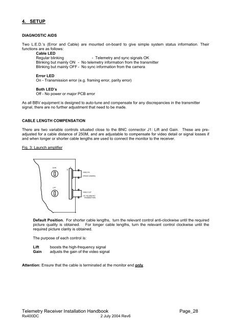
4. SETUPDIAGNOSTIC AIDSTwo L.E.D.’s (Error and Cable) are mounted on-board to give simple system status information. Theirfunctions are as follows:Cable LEDRegular blinking- Telemetry and sync signals OKBlinking but mainly ON - No telemetry information from the transmitterBlinking but mainly OFF - No sync information from the cameraError LEDOn - Transmission error (e.g. framing error, parity error)Both LED’sOff - No power or major PCB errorAs all BBV equipment is designed to auto-tune and compensate for any discrepancies in the transmittersignal, there are no further adjustment that need to be made.CABLE LENGTH COMPENSATIONThere are two variable controls situated close to the BNC connector J1: Lift and Gain. These are preadjustedfor a cable distance of 250M, and are adjustable to compensate for video detail or signal losses ifand when longer or shorter cable lengths are used to connect the monitor to the receiver.Fig. 3: Launch amplifierGAINJ2J2VIDEO IN(FROM CAMERA)LIFTVIDEO OUT(TO TELEMETRYTRANSMITTER)Default Position. For shorter cable lengths, turn the relevant control anti-clockwise until the requiredpicture quality is obtained. For longer cable lengths, turn the relevant control clockwise until therequired picture clarity is obtained.The purpose of each control is:LiftGainboosts the high-frequency signaladjusts the gain of the video signalAttention: Ensure that the cable is terminated at the monitor end only.Telemetry Receiver Installation HandbookRx400DC2 July 2004 Rev6Page_28