Manual - Building Block Video CCTV
Manual - Building Block Video CCTV
Manual - Building Block Video CCTV
- No tags were found...

You also want an ePaper? Increase the reach of your titles
YUMPU automatically turns print PDFs into web optimized ePapers that Google loves.
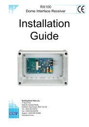
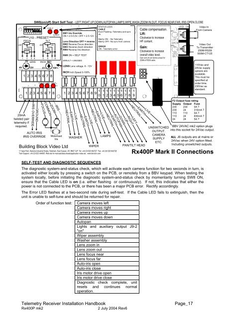
6VON20mAtwisted pairtelemetry ifrequired.1 2 3 4 5 6 7 8SW8(on/off) Start Self Test - LEFT,RIGHT,UP,DOWN,AUTOPAN,LAMPS,WIPE,WASH,ZOOM IN,OUT, FOCUS NEAR,FAR, IRIS OPEN,CLOSEJ10 - PRESETFOCUSTILT+5V 0V +5V 0VZOOMPAN1 2 3 49V LENS1 2 3 4 5 6 7 8 1 2 3 4 5 6 7 8 9 1 0GROUNDIRIS OVERRIDEFOCUSCOMMONAUTO IRISIRIS OVERRIDE5 6 7 8INCH 50%12V 0% 100%1 2 3 4 5 6 7 8ZOOMIRISMotorisedIris<strong>Building</strong> <strong>Block</strong> <strong>Video</strong> LtdSW1 Iris OverrideON = 2.5-5.5V, OFF = 2.5-12VLens Directios OFF = reverseSW2 Reverse Focus directionSW3 Reverse Zoom directionSW4 Reverse Iris directionSW8 ON = SELF TESTSW5,6,7 = UNUSEDLENS Lens voltage. 6 - 12VINCH Inch Speed 0-100%NEUTRALNEUTRAL1 1 1 11 2 3 417 Apex Park, Diplocks Industrial Estate, Hailsham, East Sussex, UK. BN27 3JF. Tel: +44 (0)1323 842727 Fax: +44 (0)1323 842728Tech Support: +44 (0)1323 444600 Web site for manuals/data sheets/application notes etc. www.bbvcctv.comEARTHLIVENEUTRALWASHEREARTHLIVEEARTHWIPERSTATUS LEDSCABLEEven Flashing -Telemetry and syncok.Mainly ON - No TelemetryMainly OFF- No sync from cameraERRORON - Telemetry error.LIVENEUTRALLAMPSEARTH1 15 6AUTOPANDOWN17UP18RIGHT19NEUTRALLEFTEARTHPAN/TILT HEADCable compensation.Lift:Clockwise to increaseHF content.Gain:Clockwise to increaseoverall video level.Gain and Lift are factory preset for250M of RG59 cable.LIVEUNSWITCHEDOUTPUT.CAMERASUPPLYETC.<strong>Video</strong> InFrom Camera<strong>Video</strong> OutTo Transmitter250M-RG59500M-CT125110Vac and24Vac supplyoptions areavailable.This must bespecified atorder time.230Vac asstandard.F2 Output fuse ratingSupply Output Fuse230 230 5A T230 24 315mA T110 110 5A T110 24 630mA T24 24 5A TBBV 24VAC mk2 option plugsinto this socket for 24Vac output.ALL J6 outputs are at mains or24Vac when 24V option fitted.Including unswitched outputs.Rx400P Mark II ConnectionsSELF-TEST AND DIAGNOSTIC SEQUENCESThe diagnostic system-and-status check, which will activate each camera function for two seconds in turn, isactivated either locally by pressing a switch on the PCB, or remotely from a BBV keypad. When testing thesystem locally, before initiating the diagnostic system-and-status check by momentarily turning SW8 ON,ensure that the Cable LED is on (i.e. either flashing or continuously). If not, this indicates that either thepower is not connected to the PCB, or there has been a major PCB error. Rectify accordingly.The Error LED flashes at a two-second rate during self-test. If the Cable LED fails to extinguish, then theunit is unable to self-tune and should be returned for repair.Order of function test:Camera moves leftCamera moves rightCamera moves upCamera moves downAutopanLights and auxiliary output J9-2"on"Wiper assemblyWasher assemblyLens zoom inLens zoom outLens focus nearLens focus farAuto-iris openAuto-iris closeIris motor drive openIris motor drive closeDiagnostic check complete, unitresets and continues normaloperation.Telemetry Receiver Installation HandbookRx400P mk22 July 2004 Rev6Page_17