Manual - Building Block Video CCTV
Manual - Building Block Video CCTV
Manual - Building Block Video CCTV
- No tags were found...

Create successful ePaper yourself
Turn your PDF publications into a flip-book with our unique Google optimized e-Paper software.
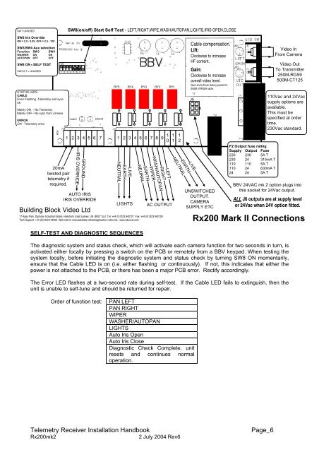
NEUTRALSW1 UNUSEDSW8(on/off) Start Self Test - LEFT,RIGHT,WIPE,WASH/AUTOPAN,LIGHTS,IRIS OPEN,CLOSESW2 Iris OverrideON = 2.5 - 5.5V, OFF = 2.5 - 12VSW3/SW4 Aux selectionFunction SW3 SW4WASHER ON ONAUTOPAN OFF OFFSW8 ON = SELF TESTSW5,6,7 = UNUSED<strong>Building</strong> <strong>Block</strong> <strong>Video</strong> LtdONSTATUS LEDSCABLEEven Flashing -Telemetry and syncok.Mainly ON - No TelemetryMainly OFF - No sync from cameraERRORON - Telemetry error.20mAtwisted pairtelemetry ifrequired.CABLEGROUNDIRIS OVERRIDEAUTO IRISIRIS OVERRIDE31 2 3 4 5 6 7 8ERROR1 2 3 4 5 6 7 1 2 3 4 5 6 7 8 9 1 0LEFTRIGHTWASH/AUTOPANWIPER17 Apex Park, Diplocks Industrial Estate, Hailsham, East Sussex, UK. BN27 3JU. Tel: +44 (0)1323 842727 Fax: +44 (0)1323 842728Tech Support: +44 (0)1323 444600 Web site for manuals/data sheets/application notes etc. www.bbvcctv.comEARTHLIVELIGHTSSELF-TEST AND DIAGNOSTIC SEQUENCESRY5 RY4 RY3 RY2 RY1NEURALEARTHAC OUTPUT1112NEUTRALEARTHCable compensation.Lift:Clockwise to increaseHF content.Gain:Clockwise to increaseoverall video level.Gain and Lift are factory preset for250M of RG59 cable.J5LIVEUNSWITCHEDOUTPUT.CAMERASUPPLY ETCF2 Output fuse ratingSupply Output Fuse230 230 5A T230 24 315mA T110 110 5A T110 24 630mA T24 24 5A T<strong>Video</strong> InFrom Camera<strong>Video</strong> OutTo Transmitter250M-RG59500M-CT125110Vac and 24Vacsupply options areavailable.This must bespecified at ordertime.230Vac standard.BBV 24VAC mk 2 option plugs intothis socket for 24Vac output.ALL J6 outputs are at supply levelor 24Vac when 24V option fitted.Rx200 Mark II ConnectionsThe diagnostic system and status check, which will activate each camera function for two seconds in turn, isactivated either locally by pressing a switch on the PCB or remotely from a BBV keypad. When testing thesystem locally, before initiating the diagnostic system and status check by turning SW8 ON momentarily,ensure that the Cable LED is on (i.e. either flashing or continuously). If not, this indicates that either thepower is not attached to the PCB, or there has been a major PCB error. Rectify accordingly.The Error LED flashes at a two-second rate during self-test. If the Cable LED fails to extinguish, then theunit is unable to self-tune and should be returned for repair.Order of function test:PAN LEFTPAN RIGHTWIPERWASHER/AUTOPANLIGHTSAuto Iris OpenAuto Iris CloseDiagnostic Check Complete, unitresets and continues normaloperation.Telemetry Receiver Installation HandbookRx200mk22 July 2004 Rev6Page_6