You also want an ePaper? Increase the reach of your titles
YUMPU automatically turns print PDFs into web optimized ePapers that Google loves.
selos<br />
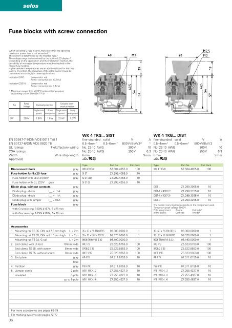
Fuse blocks with screw connection<br />
When selecting G fuse inserts, make sure that the specified<br />
maximum power loss is not exceeded. 1)<br />
The current is determined by the inserted fuse. 1)<br />
The voltage range is determined by the built-in LED display. 2)<br />
Depending on the application and the installation method, the<br />
possibility of increased temperature must be checked in the<br />
closed fuse holde<strong>rs</strong>.<br />
Higher ambient temperatures are an additional load for the fuse<br />
inserts. Therefore, the reduction of the rated current must be<br />
considered accordingly in these applications.<br />
Indicator (24 V):<br />
Indicator (220 V):<br />
Lamp color: red<br />
Power consumption: 10,3 mA<br />
Lamp color: red<br />
Power consumption: 0.3 mA<br />
1)<br />
Maximum power loss at 23° C ambient temperature<br />
(according to DIN EN 60947-7-3)<br />
Typ<br />
Rated<br />
Voltage<br />
Overload protection<br />
Single arrangement<br />
Exclusive shortcircuit<br />
protection<br />
Group Single arrangement<br />
arrangement<br />
Group<br />
arrangement<br />
SIST 250 V 1.6 W 1.6 W 2.5 W 1.6 W<br />
EN 60947-7-1/DIN VDE 0611 Teil 1<br />
EN 60127-6/DIN VDE 0820 T6<br />
UL ratings<br />
Field/factory wiring<br />
CSA ratings<br />
Width<br />
Wire strip length<br />
Approvals<br />
Disconnect block<br />
gray<br />
Fuse holder for 5 x 20 fuse<br />
gray<br />
Fuse holder with LED 24-60 V<br />
gray<br />
Fuse holder with GL 220 V gray<br />
Diode plug, without contacts<br />
gray<br />
Diode plug - diode I max<br />
= 1 A gray<br />
Diode plug - diode I max<br />
= 1 A gray<br />
Diode plug with jumper I max<br />
= 10 A gray<br />
Fuse block<br />
gray<br />
with G-screw cap B DIN 41674, 5 x 25 mm<br />
with G-screw cap A DIN 41674, 5 x 20 mm<br />
WK 4 TKG... SIST<br />
fine-stranded solid V A<br />
0.5 - 4 mm 2 0.5 - 6 mm 2 800 V / 8 kV / 3 2) 1)<br />
No. 22-10 AWG 300 V 10<br />
No. 20-10 AWG 250 V 6.3<br />
6 mm 9 mm<br />
gqw<br />
Type Part No. Std. Pack<br />
WK 4 TKG/U 57.504.4055.0 100<br />
Si ST Z1.299.4055.0 10<br />
Si ST LED Z1.299.4155.0 10<br />
Si ST GL Z1.299.4255.0 10<br />
WK 4 TKG... DIST<br />
fine-stranded solid V A<br />
0.5 - 4 mm 2 0.5 - 6 mm 2 800 V / 8 kV / 3<br />
No. 22-10 AWG 300 V 10<br />
No. 20-10 AWG 250 V 6,3<br />
6 mm 9 mm<br />
gqw<br />
Type Part No. Std. Pack<br />
WK 4 TKG/U 57.504.4055.0 100<br />
DIST ... Z1.299.3055.0 10<br />
DIST-1 N 4007-1 3) Z1.299.3155.0 10<br />
DIST-1 N 4007-2 4) Z1.299.3355.0 10<br />
DIST-D Z1.299.3255.0 10<br />
The current carrying load depends on the component used.<br />
Temporary peak voltage 1000 V.<br />
Pole assignment Anode Cathode 3)<br />
of the diode: Cathode Anode 4)<br />
Accessories<br />
1. Mounting rail TS 35, DIN rail 7.5 mm high L = 2 m<br />
Mounting rail TS 35, DIN rail, 15 mm high L = 2 m<br />
Mounting rail TS 32, G rail<br />
L = 2 m<br />
2. End clamp with U-foot 10 mm wide<br />
End clamp TS 35, with screw 8 mm wide<br />
End clamp TS 35, without screw 8 mm wide<br />
3. End plate gray<br />
blue<br />
4. Partition gray<br />
5. Jumper comb 2 pole<br />
insulated<br />
3 pole<br />
up to 6 pole<br />
35 x 27 x 7,5 EN 60715 98.300.0000.0 1<br />
35 x 27 x 15 EN 60715 98.370.0000.0 1<br />
9006 EN 60715 G-32 98.190.0000.0 1<br />
WE 1/U Z5.523.5753.0 100<br />
9708/2 S 35 Z5.522.8553.0 100<br />
WEF 1/35 Z5.523.9353.0 100<br />
AP 4 TK 07.311.6155.0 10<br />
TW 4 TK 07.311.8155.0 10<br />
IVB 1 WK 4..-2 Z7.255.4227.0 10<br />
IVB 1 WK 4..-3 Z7.255.4327.0 10<br />
IVB 1 WK 4..-6 Z7.255.4627.0 10<br />
36<br />
For more accessories see pages 62-79<br />
For marking systems see pages 72-77


